Jialing-Gespann JH600 User manual

JH600 Maintenance Manual
Overview
-1-
1
Overview
Engine Number Position Bar Tool
Maintenance Precautions Maintenance Period Table
Technical Data of Main Performance Wiring Diagram
Standard Torque Values Symbol Descriptions
Engine Number Position
Photo of Complete Vehicle:
Frame Number Position:
Engine Number Position:
Name Plate
Frame
Number
Engine
Number
Name Plate
Position:

JH600 Maintenance Manual
Overview
-2-
Maintenance Precautions
1. Use only the spare parts, fittings, lubricating oil
and other auxiliary materials produced,
recognized or recommended by China Jialing
Industrial Co., Ltd. (Group). Using spare parts
not conforming to the “Jialing” specifications or
requirements may cause damage to the
motorcycle.
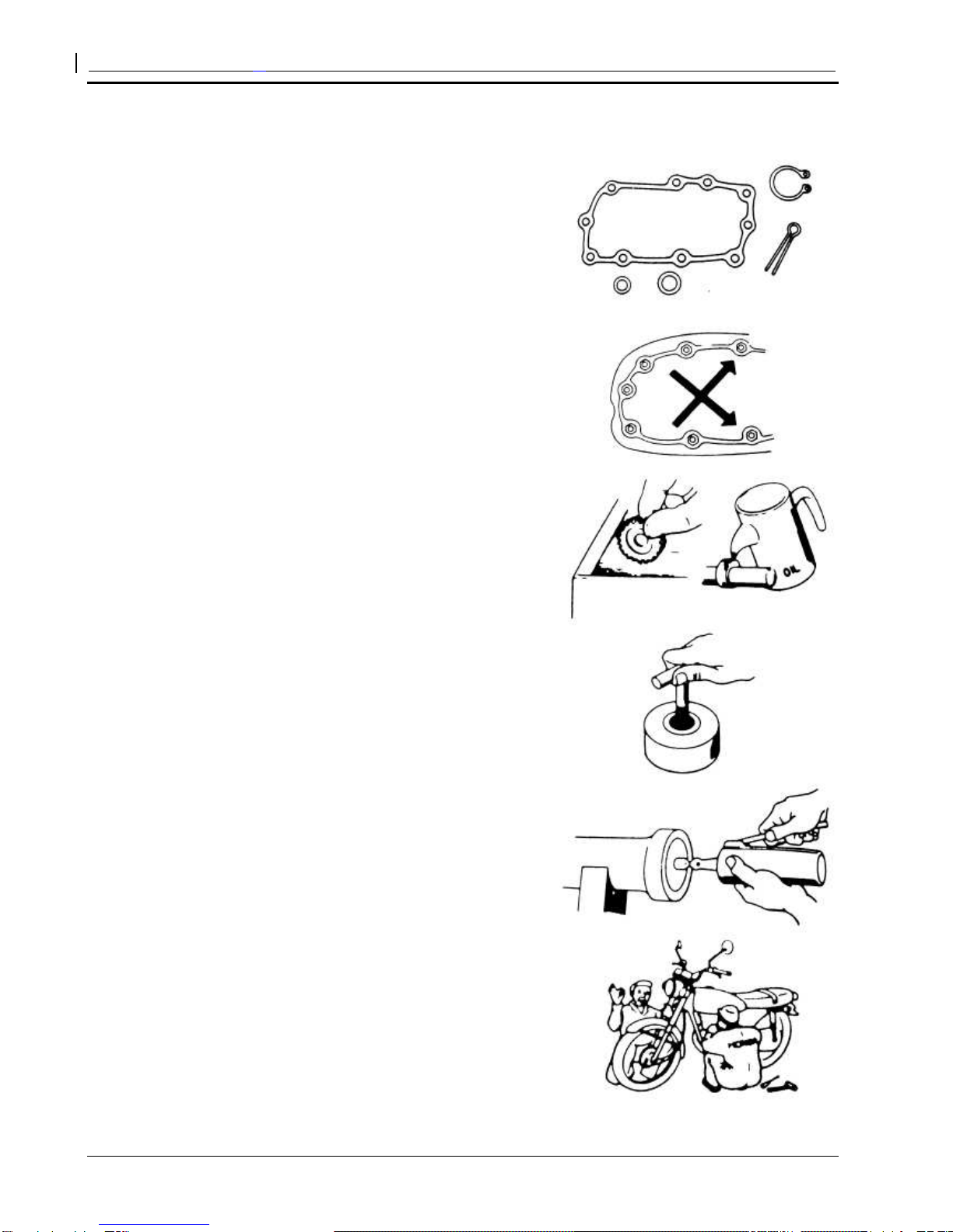
2. Whenever reassembling after being
disassembled, replace new washers, sealing
members, etc.
3. While fastening bolts or nuts, proceed in diagonal
crossing sequence to gradually screw down to
the required torque for 2 to 3 tries.
4. After being disassembled, the parts and
components should be cleaned before being
inspected and measured.
To clean the spare parts, use only the cleaning
fluid that is incombustible or has high ignition
point.
Before reassembling, apply the specified
lubricating oil to the sliding surface of the parts
and components.
After reassembling, check whether all the spare
parts are mounted properly by means of turning,
moving and operating them.
5. To disassemble and assemble a motorcycle,
special service tools (SST) and general-purpose
tools must be used in accordance with relevant
regulations.
6. The specified or equivalent lubricating grease
(oil) must be applied to or refilled into the
specified locations.
7. When 2 or more persons are carrying out the
operation, they shall work with each other and
pay attention to safety.

JH600 Maintenance Manual
Overview
-3-
8. Before operating, always remove the negative (-)
end of the battery first and take care to prevent
the wrench or the like from touching the frame.
After operating, reconfirm all the connections,
fixings and junctions. If the battery is already
removed, connect the positive (+) end first.
9. In case the fuse is blown, check for the causes
and, after being repaired, replace corresponding
fuse as per the specified capacity.
10. The caps must be securely put on the terminals
after the operation is complete.
11. While disassembling a connector joints with lock,
release the lock before proceeding with
operation.
While disassembling a connector joints, hold the
connector body without pulling the wire harness.
Before connecting the connector, the terminals
shall be free from breaking or bending. Make
sure the terminals are not too long or are falling
off.
Confirm capacity!

JH600 Maintenance Manual
Overview
-4-
The connector shall be fully inserted in place.
For a connector with lock, confirm whether the
lock is completely fixed.
Make sure the harness is not falling off
Make sure the plastic jacket of the connector is
securely covering the connector without scaling
off.
12. Before connecting a connector, make sure the
sleeve is not broken and the opening of the
intermediate terminal is not too large.
The joint shall be fully inserted in place.
Make sure the plastic jacket is housing the
terminal completely. The opening of the plastic
jacket shall not face up.
13. The harness fixing strap shall firmly button the
specified position on the frame.
14. The clamp shall reliably bite the wire harness.
In case of a welded clamp, it shall not bite the
wire harness towards the weld mark.
The wire harness shall be clamped at the
position without contacting a rotating part or a
removing element.
Crackle

JH600 Maintenance Manual
Overview
-5-
The wire harness shall be clamped at the
position without contacting a part that generates
high temperature.
The wire harness shall be clamped at the
position without contacting the edge or sharp
corners of the vehicle body.
The wire harness shall be incapable of passing
through the position contacting a bolt, a screw
head or any front part.
The wire harness shall not be slackened or be
forcibly pulled.
If the wire harness has to contact the edge or
sharp corner parts, the contacting part shall be
protected with hose or adhesive tape.
In case of a wire harness with garland, it shall be
reliably harnessed.
Do not damage the garnish of the wire harness.
Once the wire harness is damaged, repair it by
coiling with plastic adhesive tape.
While mounting parts and components, do not
press the wire harness.
Do not touch!
Do not pull!
Pay attention
not to press it.

JH600 Maintenance Manual
Overview
-6-
Do not mount wire harness with it twisted.
15. When wiring, note when turning it leftwards or
rightwards to the limit position, the wire harness
shall not be tightened up or slackened, and
make sure there is no significant bending,
pressing, intervening of marginal parts.
16. While using the test table, operate according to
the maintenance manual after understanding the
explanations in the instruction manual.
17. Do not drop or throw the parts and components.
18. In case of rust on the terminals, carry out
connection operation after disposing it with
abrasive paper, etc.
19. Do not forcibly twist or forcefully bend the cable.
Because a deformed or damaged cable is the
cause of bad operation and damage.
Rust must be
eliminated!
Have you learned by
heart the method of
application? Are the
measurement range and
polarity in accordance
with the instruction
manual?

JH600 Maintenance Manual
Overview
-7-
Technical Data of Main Performance
Item
Data
Dimension
& Weight
Length
Width
Height
Wheelbase
Min. ground clearance
Complete vehicle weight
2,210mm
860mm
1,330mm
1,470mm
200mm
Non-loaded weight: 195kg, Curb weight: 210kg, Fully loaded
weight: 390kg
Vehicle
body
Frame type
Rake angle
Front suspension device
Rear suspension device
Front Tire size
Rear Tire size
Front wheel pressure
Rear wheel pressure
Front brake
Rear brake
Fuel tank volume
Fuel grade
Cradle type
28.5°
Sleeve type, spring & hydraulic composite damping
Rocker arm type, adjustable spring & hydraulic composite
central damping
100/90-19 57S
130/80-17 65S
Normally loaded: 300 kPa, Fully loaded: 350 kPa
Normally loaded: 360 kPa, Fully loaded: 450 kPa
Single disc type Diameter Φ300mm
Single disc type Diameter Φ240mm
19L
93#
Engine
Mode
Cylinder bore × Stroke
Cylinder displacement
Compression ratio
Max. power
Max. torque
Valve clearance (cold)
Valve driving gear
Air filter
Cooling method
Cooling water charging
volume
Crankshaft balance system
Lubrication method
Fuel pump type
Engine oil grade
Engine oil charge volume
Engine oil filter element
Electric motor starting
Idle speed
Net weight of engine
Single-cylinder water-cooling 4-valve top-mounted camshaft
type 4-stroke engine
94mm ×85mm
589.9cc
9.7:1
28.5kw/6000rpm
50N.m/4500rpm
IN: 0.09-0.14,EX: 0.17-0.22
Chain drive
Oilpaper filter
Water-cooling
1.2L
Balance shaft
Pressure / Splash
Secondary cycloid
10W/40 (SG Grade)
2.3L
Oilpaper filter
Engine starting
1500±150r/min
49kg

JH600 Maintenance Manual
Overview
-8-
Item
Data
Driving
system
Clutch
Clutch operating system
Variable speed gear
Primary reduction ratio
Transmission gear ratio
Final reduction ratio
Gear shifting mode
Wet clutch, coil clutch, paper friction wafer
Manual mechanical
5-speed constant mesh
2.345
Ⅰ
ⅠⅠ
Ⅰ
2.571
2.5712.571
2.571
Ⅱ
ⅡⅡ
Ⅱ
1.647
1.6471.647
1.647
Ⅲ
ⅢⅢ
Ⅲ
1.200
1.2001.200
1.200
Ⅳ
ⅣⅣ
Ⅳ
0.957
0.9570.957
0.957
V
V V
V
0.800
0.8000.800
0.800
3.000
Left foot operated to and back type
Sequence: I-
--
-N-
--
-Ⅱ
ⅡⅡ
Ⅱ-
--
-Ⅲ
ⅢⅢ
Ⅲ-
--
-Ⅳ
ⅣⅣ
Ⅳ-
--
-V
VV
V
Electrical
system
Electric generator
Accumulator capacity
Power supply system
Fusible cutout
Spark plug
Spark plug gap
Ignition coil type
Fuel supply mode
Ignition mode
Ignition advance angle
Ignition timing
Front lamp
Turn lamp
Stop / Rear-position lamp
330w/5000rpm, permanent magnet AC magneto
12V 14A.h
DC power supply, and the electric generator is only
used to recharge the accumulator
30A
Chinese model NHSP B8RC, Japanese model NGK
CR8E
0.7-0.8mm
Open magnetic circuit
Electronically injection, ECU control
EMS
EMS
EMS
2×12V35W/35W
Front: 12V21W Rear: 12V21W
12V21W/5W

JH600 Maintenance Manual
Overview
-9-
Standard Torque Values
ENGINE
Item Quantity
Thread
diameter
(mm)
Torque value
(N.m) Thread locker
Cylinder head connecting bolt 12 6 10~14
Cylinder bolt 4 10 48~52
Valve adjusting screw nut 4 5 7~11
Timing driven sprocket bolt 2 6 10~14
Rocker-arm shaft cover 2 14 24~28
Magneto flywheel fastening nut 1 18 171~189 LOCTITE 243
Clutch fastening nut 1 18 114~126 LOCTITE 243
Primary driving gear fastening nut 1 18 143~157 LOCTITE 243
Oil drain plug 1 14 28~32
Crankshaft, main-shaft bearing baffle
screw 5 6 8~12 LOCTITE 648
Screw M5*12 (GB/T818-2000) 3 5 6~9 LOCTITE 648
Gearshift drum plate connecting bolt 1 6 10~14
Gearshift shaft set bolt 1 8 23~27
Stud 7 6 8~12 LOCTITE 648
Stud 1 8 10~14
Exhaust valve stud bolt 2 8 10~14 LOCTITE 243
Freewheel and flywheel connecting
screw 6 8 23~27 LOCTITE 243
Stator connecting bolt 3 6 10~14 LOCTITE 648
Stator leads pressure plate bolt 2 6 10~14 LOCTITE 648
Spark Plug 1 10 14~18
Driving primary driving gear fastening
nut 3 6 10~14 LOCTITE 648
Liquid tube set bolt 1 8 10~14
Water temperature sensor 1 12 27~33
Tensioner plate fastening bolt 1 8 23~27

JH600 Maintenance Manual
Overview
-10-
Vehicle body
Item Quantity
Thread diameter
(mm)
Torque value
(N.m)
Thread
locker
Front wheel spindle 1 16 50~60
Front vibration damper plate 4 6 8~12
Real wheel spindle nut 1 18 80~100
Rear fork shaft nut 7 14 60~70
Engine hanging bolt 5 10 39~49
8 8 25~35
Steering handle set bolt 4 8 20~30
Front fork vertical pipe cap nut 1 22 60~70
Upper / lower connection plate
set
bolt 6 8 25~35
Rear sprocket bolt 6 8 20~30 LOCTITE 243
Brake disc fastening nut 18 8 20~30 LOCTITE 243
Banister fastening nut 4 8 18~25
Damping rocker arm bolt and nut 3 10 34~44 LOCTITE 243
Speed signal panel screw 3 4 0.5~1 LOCTITE 243
Front brake caliper screw 2 10 34~44 LOCTITE 243
4 8 18~25 LOCTITE 243
In addition to the torque values of the important parts as listed above, the torque values for other
standard fasteners are as follow:
Name and dimensions
Torque value (N.m)
5mm bolt & nut 4.5 ~6
6mm bolt & nut 8 ~12
8mm bolt & nut 18 ~25
10mm bolt & nut 30 ~40
12mm bolt & nut 50 ~60
5mm Screw 3.5 ~5
6mm Screw 7 ~11
6mm spool bolt & nut 10 ~14
8mm spool bolt & nut 20 ~30
10mm spool bolt & nut 30 ~40

JH600 Maintenance Manual
Overview
-11-
Bar Tool
Special Service Tools (SST)
Tool Name
Number
Diagram
Reference sections
Counter shaft oil seal guide F02F000001 10
Rotor fastening tool F02F000002 9
Sprocket fastening tool F02F000003
Variable-speed shaft oil seal
guide F02F000004 8、10
Piston sliding scale base F02F000007 7
Oil shield press-in buck F02F000008 7
Rocker-arm shaft locating tool F02F000009 7
Fastening tool F02F000010 2、8
Crankshaft oil seal press-in
buck F02F000012 8
Clutch control rod oil seal guide
F02F000013 8
Valve clearance adjusting tool F02F000015 3、7
Clutch push rod assembler F02F000026 2、8
Clutch push rod extractor F02F000027 2、8
Tensioner locking key F02F000028 3、7、9

JH600 Maintenance Manual
Overview
-12-
(Continued) Special Service Tools (SST)
Rotor extractor F02F000029 9
Valve dismantling tool
7
Gearshift drum oil seal guide F02CF000001
10
Spoke nut fastening tool X02F000001
3
Special socket for adjusting nut
X02F000002
12
Rear damper adjusting wrench
X02F000003
13
Special socket for
thermoswitch X02F000004
5
Bumper oil seal buck X02F000005-1
13
Rocker arm oil seal buck I X02F000005-2
13
Rocker arm oil seal buck II X02F000005-3
13
Riveting gun
Anchor ear pliers

JH600 Maintenance Manual
Overview
-13-
General-purpose Tools (Reference)
Tool Name BRIEF DESCRIPTION
Reference
sections
T-type wrench 8# Ultra thin
T-type wrench 9#
T-type wrench 10#
T-type wrench 12#
T-type wrench 13#
T-type wrench 14#
T-type wrench 15#
Hexagonal socket 8 1/4″joint, overall length 23mm
Hexagonal socket 10 1/4″joint, overall length 23mm
Hexagonal socket 13 1/4″joint, overall length 23mm
Stud bolt socket M6 1/2″joint, overall length 55mm
Stud bolt socket M8 1/2″joint, overall length 55mm
Hexagonal socket 8 1/2″joint, overall length 38mm
Hexagonal socket 8 1/2″joint, overall length 38mm, ultra thin
Hexagonal socket 9 1/2″joint, overall length 38mm
Hexagonal socket 10 1/2″joint, overall length 38mm
Hexagonal socket 10 1/2″joint, overall length 125mm, connecting rod type
Ultra thin
Hexagonal socket 11 1/2″joint, overall length 38mm
Hexagonal socket 12 1/2″joint, overall length 38mm
Hexagonal socket 13 1/2″joint, overall length 38mm
Hexagonal socket 14 1/2″joint, overall length 38mm
Hexagonal socket 14 1/2″joint, overall length 78mm, ultra thin
Hexagonal socket 15 1/2″joint, overall length 38mm
Hexagonal socket 16 1/2″joint, overall length 38mm
Hexagonal socket 17 1/2″joint, overall length 38mm
Hexagonal socket 18 1/2″joint, overall length 38mm
Hexagonal socket 19 1/2″joint, overall length 38mm
Hexagonal socket 21 1/2″joint, overall length 38mm
Hexagonal socket 24 1/2″joint, overall length 45mm
Hexagonal socket 27 1/2″joint, overall length 50mm
Hexagonal socket 27 1/2″joint, overall length 78mm, ultra thin, Ex.
diameter ≤φ37
Hexagonal socket 29 1/2″joint, overall length 50mm
Spark plug socket 16 1/2″joint, φ22.5×64mm
Connecting rod Joint, 12.7mm×12.7mm, length 100mm
Connecting rod Joint, 12.7mm×12.7mm, length 75mm
L-type wrench Joint, 12.7mm, length 260mm
Hooke’s universal joint Joint, 12.7mm × 12.7mm
Hooke’s universal joint Joint, 6.3mm × 6.3mm
Steering joint 12.7mm turn to 6.3mm
ratchet wrench 6.3 6.3mm joint

JH600 Maintenance Manual
Overview
-14-
(Continued) General-purpose Tools (Reference)
Ratchet wrench 12.7 12.7mm joint
Ball point Allen wrench
Standard length, metric system, 1.5, 2, 2.5, 3, 4, 5, 6,
8 and 10mm, 9-Pc, 1 set
Ball point Allen wrench
Shortened length, metric system, 1.5, 2, 2.5, 3, 4, 5,
6, 8 and 10mm, 9-Pc, 1 set
Straight nose retainer pliers
for shaft use 7″
Straight nose retainer pliers
for hollow use 7″
Monkey wrench
Needle nose pliers 6″
Percussive screwdriver set
Copper hammer
Iron hammer
Bakelite hammer
Clearance gauge
Small flashlight
Tweezers
Oil stone
Torque wrench 7# Measurement range 6-10 N.m
Torque wrench 8# Measurement range 40-200 N.m
Combination wrench 9#
Combination wrench 10#
Combination wrench 11#
Combination wrench 12#
Combination wrench 13#
Combination wrench 15#
Combination wrench 16#
Combination wrench 17#
Combination wrench 18#
Slotted screwdriver with
through tang 8×200mm, with magnetic head at opening
Slotted screwdriver 6×38mm, with magnetic head at opening
Slotted screwdriver 5×75mm, with magnetic head at opening
Slotted screwdriver 5×100mm, with magnetic head at opening
Slotted screwdriver 6×150mm, with magnetic head at opening
Cross screwdriver with
through tang 3#×200mm, with magnetic head at opening
Cross screwdriver 1#×75mm, with magnetic head at opening
Cross screwdriver 2#×38mm, with magnetic head at opening
Cross screwdriver 2#×100mm, with magnetic head at opening
Cross screwdriver 2#×150mm, with magnetic head at opening
Oil can
Dust-blowing gun
Tire gauge
File
Maintenance tool wagon 411×572×720 (excl. wheel height)

JH600 Maintenance Manual
Overview
-15-
Maintenance Period Table
Maintenance times
Maintenance Items Period Odometer km (Remark 2)
2000
k m
4,000
km
8,000
km
12,000
km
Remarks
* Fuel system passage
I
I
I
** Fuel precision filter Replace for every 15000km driving
* Throttle operating system I III
* Throttle valve body I III
Air filter element Remark 1
CCRReplace every 8,000km driving
Oil catcher C CCClean for every 5,000km driving
Spark Plug
I
I
I
Replace every 15000km driving
Engine lubricant oil
For a motorcycle, change every 500km, 1200km and 2000km
respectively, and then change it every 3000km driving
Oil filter R Replace every 12,000km driving
* Tensioner Remark 3
II I I
both intake and exhaust Remark 3
ICheck every 8,000km driving
Clutch
I
I I I
* Driving chain
Proceed with I and L for every 500km driving
** Front and rea
r brake
system IIII
** Brake Pad I III
** Brake fluid Change every 2 years
*
Front and rear brake lamp
switch IIII
* Accumulator Monthly I III
* Suspension system I III
* Nut and bolt fastening I III
** Wheel & tire I III
** Steering column bearing
I
I
I
I
** Steering backstay cable
Inspect every 5000km driving and replace every 10000km driving
Maintenance shall be carried out to the motorcycle in a specified period. The meanings of various symbols in
the list are as follows:
I: Carry out inspection, cleaning, adjustment, lubrication or replacement. C: Cleaning. R: Replacement. A:
Adjustment. L: Lubrication.
* This item is subject to maintenance by persons from Jialing Service Station. If the user has special
service tools, maintenance accessories or maintenance ability, it can repair it by itself.
** To ensure safety, this item is only subject to maintenance by persons from Jialing Service Station.
Remarks:
①While driving in a dusty area, it shall be cleaned more often.
②When the odometer reads more than the given maximum value, its maintenance period shall still
repeat as per the mile interval as stipulated in the table.
③To ensure safety, the adjustment of timing chain and valve clearance shall only be carried out by
persons from Jialing Service Station.

JH600 Maintenance Manual
Overview
-16-
Wiring Diagram
D
C
B
A
E
F
G

JH600 Maintenance Manual
Overview
-17-
Magnified view of Part A
Right switch leads
Instrument connecting wire
Main cable
Left turn lamp connecting wire
Clutch handle seat leads
Left combination switch leads
Right switch leads
Right turn lamp connecting wire
Vehicle speed sensor leads

JH600 Maintenance Manual
Overview
-18-
Shift position switch leads
Magnified view of Part B
Main cable components Starting motor connecting wire ( - )
Water temperature
sensor connecting wire
Magneto leads
Rear brake switch leads
Starting motor connecting wire ( + )
Magnified view of Part C
Air filter connecting wire (Main cable)
Variable voltage rectifier leads
Shift position
switch patch plug
Variable voltage
rectifier patch plug Oxygen sensor patch plug
Fuel pump connecting patch plug

JH600 Maintenance Manual
Overview
-19-
Magnified view of Part D
Magnified view of Part E
Accumulator
connecting wire ( + )
Starting relay Headlight controller
ECU controller & patch plug
Flasher
Fuel pump relay
Accumulator connecting wire ( - )
Complete
vehicle fuse Variable voltage
rectifier
Rear position lamp connecting
wire (Main cable)
Injection nozzle patch plug
Intake air temperature
sensor patch plug
Starting motor connecting wire ( - )
Rear brake switch leads

JH600 Maintenance Manual
Overview
-20-
Magnified view of Part F
Speed sensor connecting wire
Phase sensor
Thermoswitch connecting wire (Main cable)
Intake negative pressure transducer
Water temperature sensor Throttle position sensor patch plug
Table of contents