P OWE R C ONNE C T IONS
Before installing the amplifier,disconnectthe
negative (ground)wire from the vessel’sbattery.
This willpreventaccidentaldamage to the system,
the vesseland yourbody during installation.
The M600/1’s+12 VDCand Ground
connectionsare designed to accept4 AWG
power wire.4 AWG is the required wire size for
this amplifier.
Ifyou are installing the M600/1 with other
amplifiersand wish to use a single main power
wire,use 2 AWG or1/0 AWG main power wire
(depending on the overallcurrentdemandsofall
the amplifiersin the system).This2 AWG or
1/0 AWG powerwire should terminate into a
fused distribution block mounted as close to
the amplifiersas possible (within 12 inches /
30cm ofwire length).The fused outputofthe
distribution block willconnectto the M600/1
C oX ™ ™ bd ” k
fused distribution blocksare recommended
pU4WUSm4A ” pU4WUSm4C
Note:SmallerAWG numbers mean bigger
wire and vice-versa (1/0 AWG is the largest,2
AWG is smaller,then 4 AWG,then 8 AWG,etc.).
To connectthe power wiresto the amplifier,
firstback outthe setscrew on the top ofthe
terminalblock,using the supplied 2.5 mm hex
wrench.Strip 1/2 inch (12 mm)ofinsulation from
the end ofeach wire and insertthe bare wire into
the terminalblock,seating itfirmly so thatno
bare wire isexposed.While holding the wire in
place,tighten the setscrew firmly,taking care not
to strip the head ofthe screw.
The ground connection should be made using
the same gauge wire asthe power connection.
Any wires run through barriers must
be protected with a high quality rubber
grommetto preventdamage to the
insulation ofthe wire.Failure to do so
may resultin a dangerous shortcircuit.
Many vessels employ small(10 AWG -6 AWG)
wire to connectthe alternator’spositive
connection to the battery.To preventvoltage
drops,this wire should be upgraded to 4 AWG
when installing amplifier systemswith main
fuse ratings above 60A.
Itis common forthe alternator to be grounded
through its chassis.Ifthe alternatoris not
grounded through itschassisand instead employs
a small(10 AWG -6 AWG)wire to connectto
ground,thiswire should also be upgraded to 4
AWG when installing amplifiersystemswith main
fuse ratingsabove 60A.
F US E R E QUIR E ME NT S
Itis absolutely vitalthatthe main power
wire(s)to the amplifier(s)in the system be
fused within 18 inches(45 cm)ofthe positive
battery postconnection.The fuse value ateach
power wire should be high enough for allofthe
equipmentbeing run from thatpower wire.If
only the M600/1 is being run from thatpower
wire,we recommend a 50A fuse be used.
Iffusing the amplifiernearits power
connections(when more than one amp isbeing
run from the main power wire),use a 50A fuse.
MAXI™ (big plastic-body)fuses
are recommended.
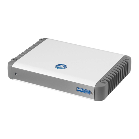
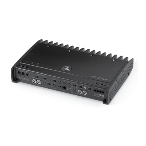
P R ODUC T DE S C R IP T ION
The M600/1 isa monoblock amplifierutilizing
bd ” f™U ™™” • ™•
to deliveroutstanding fidelity and efficiency.
The M600/1 can be operated with a wide
variety ofsource units and system configurations.
Its frequency response is limited to the range
below 500 Hz.Itisnotdesigned fordriving
midrange speakers ortweeters.Every aspectofits
operation hasbeen optimized for low-frequency
amplification.Fordetailed specifications,please
™™ ™” ™ B
T Y P IC AL INS T AL L AT ION S E QUE NC E
The following represents the sequence
fora typicalamplifierinstallation,using
an aftermarketsource unit.Additional
stepsand differentproceduresmay be
required in some applications.Ifyou
have any questions,please contactyour
authorized JL Audio dealerforassistance.
1) U•™• ™ ™™ “™
connection and secure the disconnected cable
to preventaccidentalre-connection during
installation.This step isnotoptional.
2)Run 4 AWG powerwire from the battery
location to the amplifiermounting location,
taking care to route itin such a way thatit
willnotbe damaged and willnotinterfere
with vesseloperation.Use 4 AWG orlarger
power wire and a powerdistribution block if
additionalamplifiers are being installed with
the M600/1.
3) ™• ™ ™ ™ ™ “™
post.Fuse the wire with an appropriate fuse
block (and connectors)within 18 inches (45
cm)wire length ofthe positive battery post.
This fuse is essentialto protectthe vessel.Do
notinstallthe fuse untilthe power wire has
been securely connected to the amplifier.
4) ™• ™™ ™ ™ ™ ™™
battery post.Use the same size power
™ ™ ™ •™•™” ™ +12V
connection (minimum 4 AWG).
5)Run signalcables and remote turn-on wire
from the source unitto the amplifier
mounting location.
6)Run speakercable from the subwoofer
system(s) to the amplifier mounting
location.
7)Securely mountthe amplifier.
8) ™• ™ ™ ” ™™ ™
wiresto the amplifier.A fuse nearthe
amplifierisnotnecessary ifthe M600/6 isthe
only device being run from the fused main
power wire.Ifthe fused main power wire is
shared by the M600/6 and otheramplifiers
ordevices,fuse each amplifier/device
within 12 inches(30 cm)ofwire length,
via a fused distribution block ormultiple
individualfuse blocks/on-board fuses.
9) ™• ™ ™™ 4 ™
to the amplifier.
10) ™• ™ •“™ ™ ™
11)™• ™ ™™ •“™ ™ ™
12) ™ ™™ ™ ™. •
settingsto make sure thatthey are set
according to the needs ofthe system.
13)Installthe power wire fuse (50A fora
single M600/1)and reconnectthe negative
battery postterminal.Installthe fuse (50A)
nearthe amplifier(ifapplicable).
14)Turn on the source unitata low level
to double-check thatthe amplifieris
configured correctly.Resistthe temptation
to crank itup untilyou have verified the
controlsettings.
15)Make necessary adjustments to the input
sensitivity controlsto obtain the right
overalloutputand the desired balance
in the system.See Appendix A (page 14)
forthe recommended inputsensitivity
setting method.
16)Enjoy the fruitsofyour laborwith your
favorite music.

