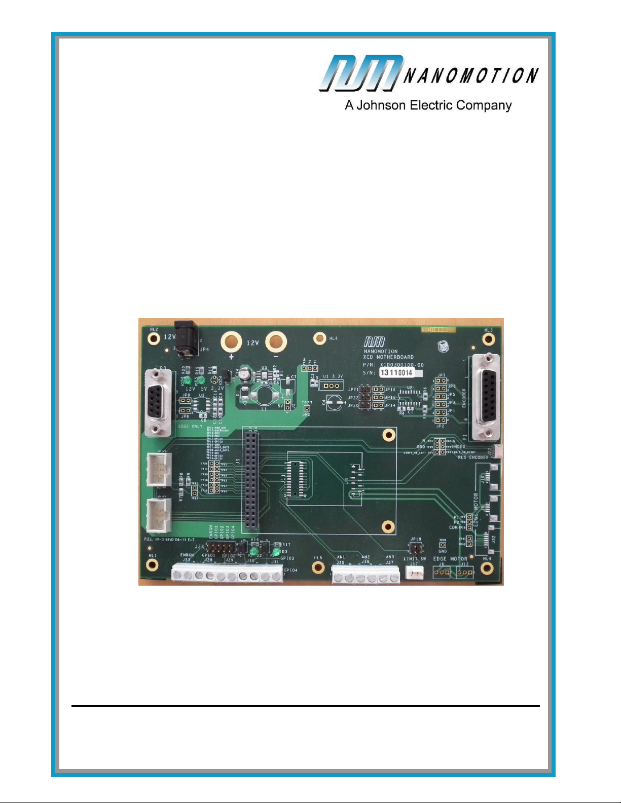
XCD HR Motherboard User Guide Copyright Notice
Document No. XCDH458001-00 rev E 2
Copyright Notice
Copyright © 2011 by Nanomotion Ltd. All rights reserved worldwide. No part of
this publication may be reproduced, modified, transmitted, transcribed, stored in
retrieval system, or translated into any human or computer language, in any form
or by any means, electronic, mechanical, magnetic, chemical, manual, or
otherwise, without the express written permission of Nanomotion Ltd., Mordot
HaCarmel Industrial Park, Yokneam, 20692, Israel.
This document contains proprietary information and shall be respected as a
proprietary document with permission for review and usage given only to the
rightful owner of the equipment to which this document is associated.
Limited Warranty
Nanomotion Ltd. (hereinafter NM) warrants the product (other than software)
manufactured by it to be free from defects in material and workmanship for a
period of time of one year (except those parts normally considered as
consumable/expendable components such as motor conditioning brushes). The
warranty commences thirty (30) days from the date of shipment.
NM warrants those parts replaced under warranty for a period equal to the
remaining warranty coverage of the original part.
NM’s sole and exclusive obligation under this warranty provision shall be to
repair, or at its sole option exchange defective products or the relevant part or
component, but only if: (i) the Purchaser reports the defect to NM in writing and
provides a description of the defective product and complete information about
the manner of its discovery within ten (10) days of its discovery; (ii) NM has the
opportunity to investigate the reported defect and to determine that the defect
arises from faulty material, parts or workmanship; and (iii) the Purchaser returns
the affected product to a location designated by NM. These provisions constitute
the exclusive remedy of the Purchaser for product defects or any other claim of
liability in connection with the purchase or use of NM products.
This warranty policy applies only to NM products purchased directly from NM or
from an authorized NM distributor or representative.
This warranty shall not apply to (i) products repaired or altered by anyone other
than those authorized by NM; (ii) products subjected to negligence, accidents or
damage by circumstances beyond NM control; (iii) product subjected to improper
operation or maintenance (i.e. operation not in accordance with NM Installation
Manuals and/or instructions) or for use other than the original purpose for which
the product was designed to be used.
NM shall not in any event have obligations or liabilities to the Purchaser or any
other party for loss of profits, loss of use or incidental, increased cost of
operation or delays in operation, special or consequential damages, whether
based on contract, tort (including negligence), strict liability, or any other theory
or form of action, even if NM has been advised of the possibility thereof, arising
out of or in connection with the manufacture, sale, delivery, use, repair or
performance of the NM products. Without limiting the generality of the preceding