Johnson T3XM User manual

JOHNSON
Issue Date 2018/4/8 Edition Doc No.
Revision Date Edition
Time Page
Johnson Industries (Shanghai) Co., Ltd
T3XM
Console
Service Manual
Approval Review Editor
Kyle Schweitzer Jerry Zhu

Contents
CHAPTER 1: SERIAL NUMBER LOCATION
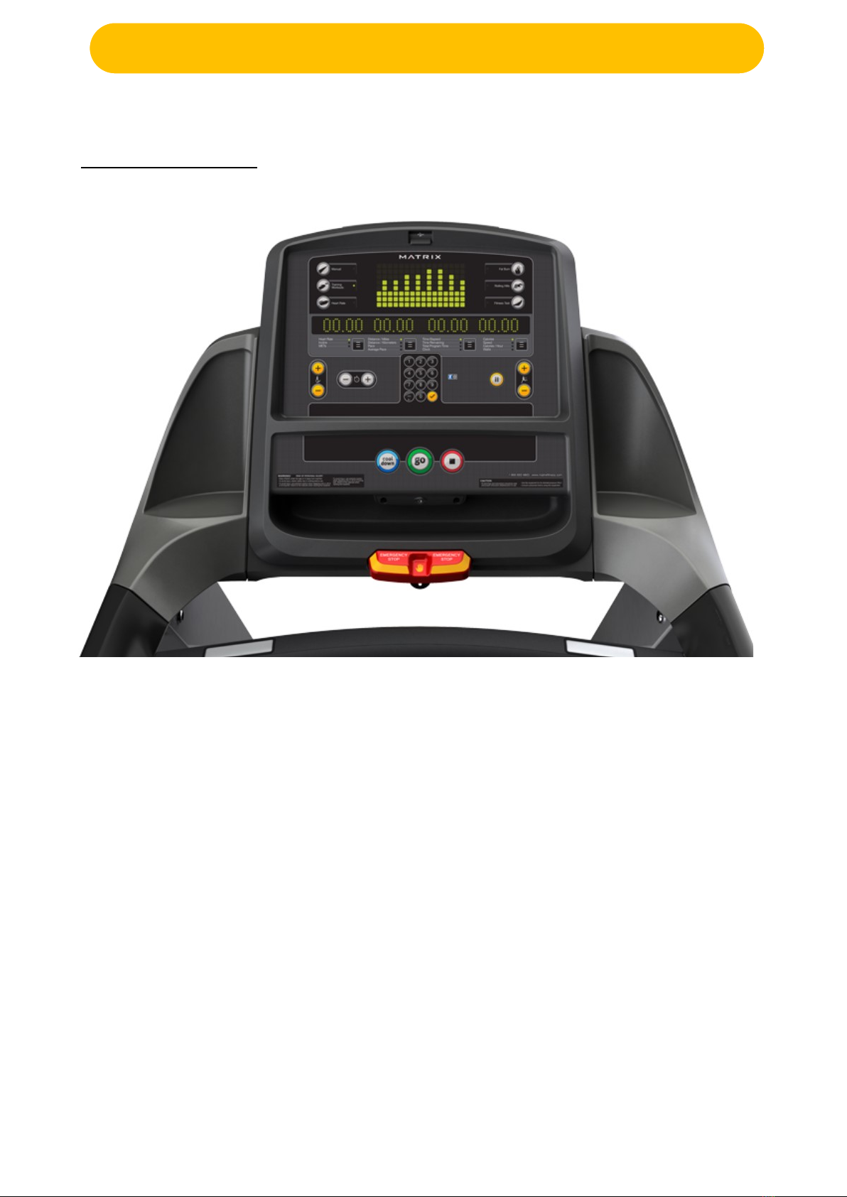
1.1 Console Overview..................................................................................................................................1
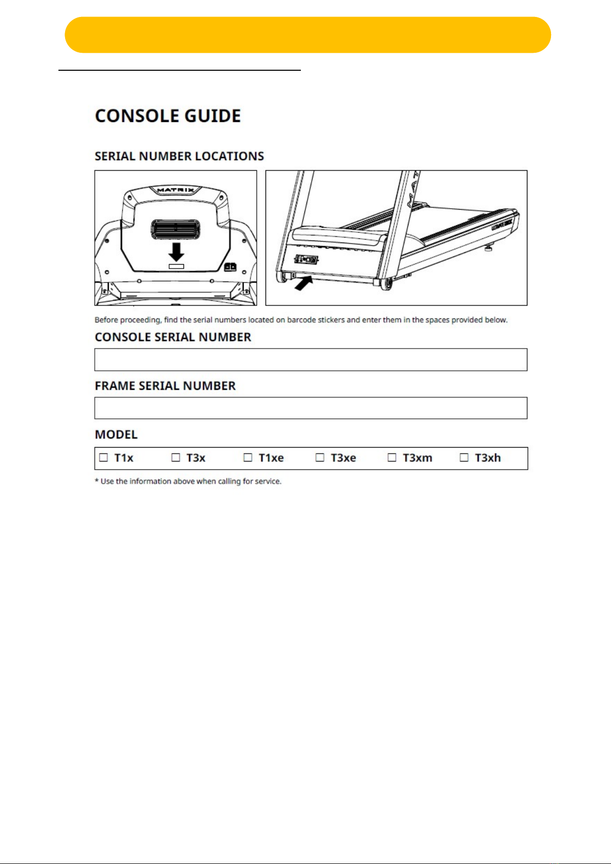
1.2 Serial Location/Model Type Apply List.................................................................................................. 2
CHAPTER 2: CONSOLE INSTRUCTION.........................................................................................................3
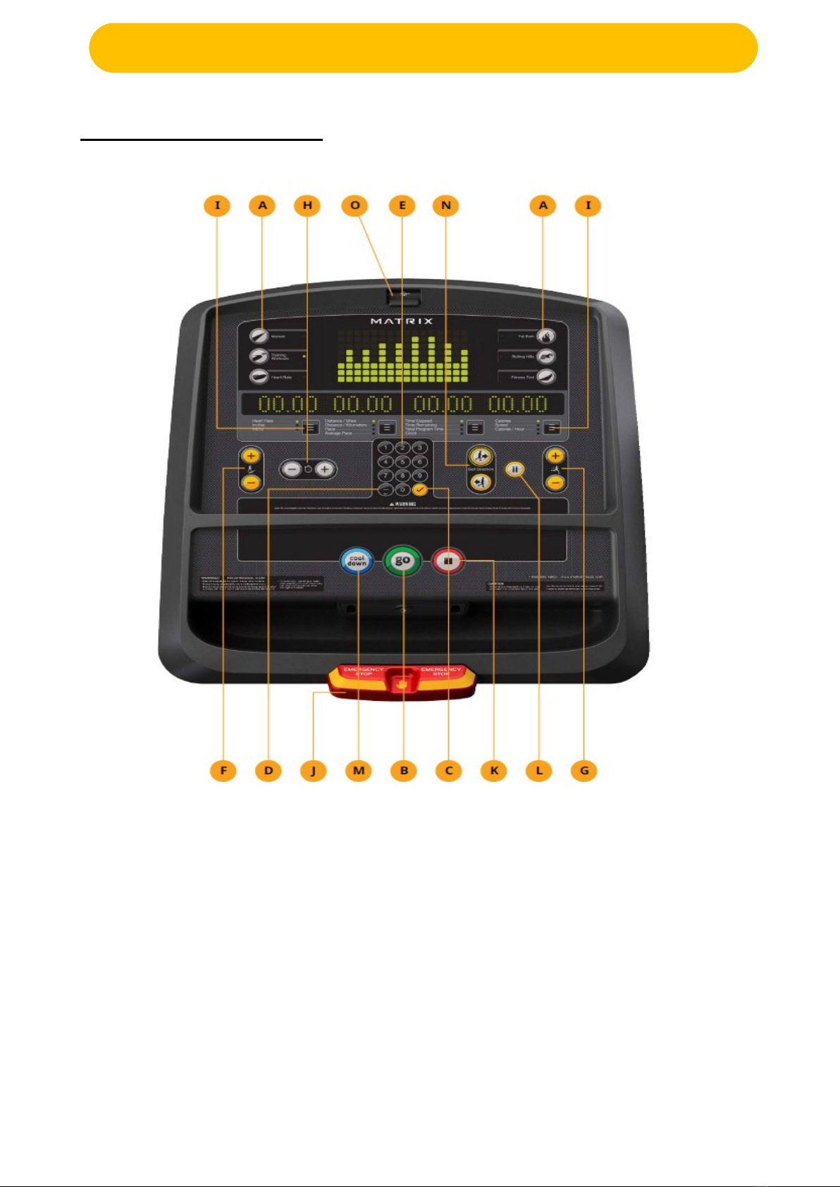
2.1 T3XM Console Description....................................................................................................................3
CHAPTER 3: CONSOLE SPECIAL MODE
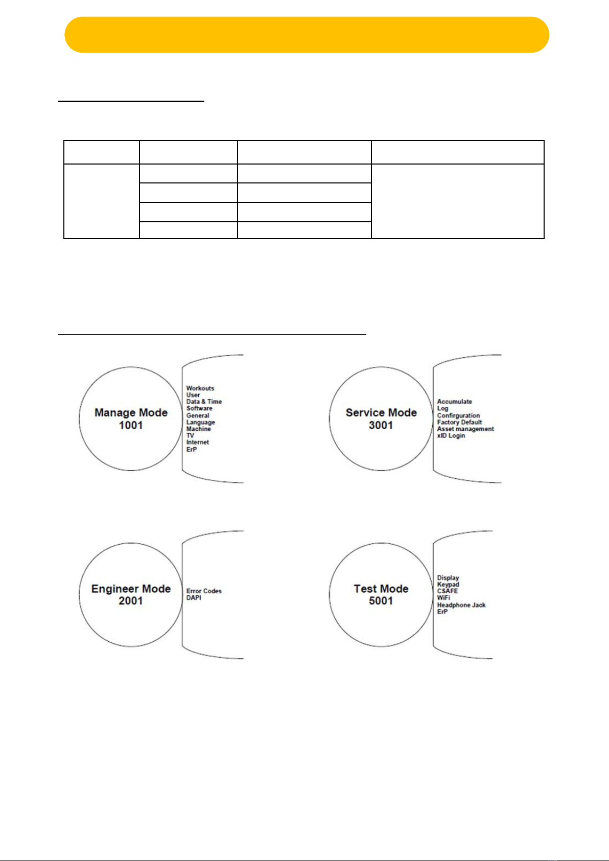
3.1 Special Mode Browse............................................................................................................................5
3.2 Manage Mode........................................................................................................................................6
3.3 Engineer Mode.......................................................................................................................................7
3.4 Service Mode.........................................................................................................................................8
3.5 Test Mode..............................................................................................................................................8
CHAPTER 4: TROUBLESHOOTING
4.1 Electrical Diagram..................................................................................................................................9
4.2 Ports Description................................................................................................................................. 10
4.3 Error Code List.....................................................................................................................................11
4.3.1.Speed Errors.......................................................................................................................... 11
4.3.2.MCB Errors.............................................................................................................................11
4.3.3. UCB Error..................................................................................................................................13
4.3.4. Communication Errors............................................................................................................. 14
4.4 Console Does Not Light Up.................................................................................................................15
SYMPTOM:..........................................................................................................................................15
SOLUTION:..........................................................................................................................................15
4.5 Speed Do Not Display......................................................................................................................... 15
4.6 Keypad/Heart Rate.............................................................................................................................. 16
SYMPTOM:..........................................................................................................................................16
SOLUTION:..........................................................................................................................................16
4.7 Safe Key Issue.....................................................................................................................................16
SYMPTOM:..........................................................................................................................................16
SOLUTION:..........................................................................................................................................16
4.8 WIFI Issue............................................................................................................................................17
CHAPTER 5: MAIN COMPONENT INSTALLATION
5.1 Wi-Fi Module Install............................................................................................................................. 18
5.1.1.Wi-Fi module Install.................................................................................................................. 18
5.1.2. Wi-Fi configuration file prepare and uploading.......................................................................18
5.1.3.Wi-Fi setup................................................................................................................................ 19

1
CH
APTER
1
:
SERIAL
NUMBER
LOCATION
CHAPTER 1: SERIAL NUMBER LOCATION
1.1 Console Overview
T3XM

2
CH
APTER
1
:
SERIAL
NUMBER
LOCATION
1.2 Serial Location/Model Type Apply List
CHAPTE 2: Troubles

3
CH
APTER
2
:
CONSOLE
INSTRUCTION
CHAPTER 2: CONSOLE INSTRUCTION
2.1 T3XM Console Description
The Matrix machine is inspected before it is packaged. It is shipped in two pieces: the base and the
console. Carefully unpack the unit and dispose of the box material. Note: There is a thin protective sheet of
clear plastic on the overlay of the console that should be removed before use.
A) WORKOUT KEYS: Simple program view and selection buttons. Press Fitness Test button to cycle through available tests.
B) GO: One Touch Start.
C) ENTER: To confirm each program setting.
D) BACK: Go to previous program setting.
E) NUMBER KEYPAD: Allows for easy number inputs.
F) UP/DOWN INCLINE: Adjust incline and make program selections.
G) UP/DOWN SPEED: Adjust speed and make program selections.
H) UP/DOWN TIME: Adjust workout time.
I) TOGGLE DISPLAY: Cycles between 3 rows of workout information displayed in LED window. The console will automatically cycle between
the workout information if the Toggle Display button is pushed and held down for 3 seconds.
J) EMERGENCY STOP / IMMOBILIZATION: To stop all functions and immobilize the unit. The emergency stop on this treadmill must be
returned to its original position in order to allow normal operation of the unit.
K) STOP: Ends workout and shows workout summary data.
L) PAUSE: Pauses workout. Pause duration can be set in manager or engineering mode.
M) COOL DOWN: Puts treadmill into Cool Down mode. Cool Down time is dependent on the length of the workout.

4
CH
APTER
2
:
CONSOLE
INSTRUCTION
N) BELT DIRECTION: Press to change belt direction from forward to reverse.
O) USB PORT: Used for software updates only.

5
CH
APTER
3
:
CONSOLE
SPECIAL
MODE
CHAPTER 3: CONSOLE SPECIAL MODE
3.1 Special Mode Browse
Mode Name
Method
Programmer List
Special Mode
Manage mode “√” + “1001” + “√”
Refer to below picture
Engineer mode “√” + “2001” + “√”
Service mode “√” + “3001” + “√”
Test mode “√” + “5001” + “√”
Notes: Press “+/-“to scroll menu.
Press “√” to refer more details about programs.
Press “←” to return.

6
CH
APTER
3
:
CONSOLE
SPECIAL
MODE
3.2 Manage Mode
Category Name Default Range
Workout
Maximum Time 60 4-99
Default Time 20 4-max
Default level 1 1-10
Pause Time 5:00 00:30/1:00/2:00/3:00/4:00/5:00
User
Age 30 10-100
Weight 150lb/68kg 50lb/23kg-400lb/182kg
Default height 72/183(inch/cm,
1inch=2.54cm) 36/91-96/244
Gender male Male/female
Date &Time
Date 30 10-100
Time 150lb/68kg 50lb/23kg-400lb/182kg
Time Zone 21 1-78
Speed Unit Standard Standard/Metric
Software
Version -- UCB/LCB/Language/Wi-Fi/boot loader
Update -- UCB/LCB/Language
Auto Update Disable/Enable/Time/Check update
General Accumulate Distance 0 0-999999
Accumulate Time 0 0-999999
Language Default Language English 12 language
Erase EEPROM -- Notes: Erase language data in EEPROM
Machine
Type -- Select the right one
Serial Number
--Console
--Frame
Input the right serial
number Console/Frame
Out of Order off On/off
Beeper on On/off
Headphone Jack
-- Notification
--enable
--30000
--Enable/Disable
--1000~1000000
USB Port
--Protection Enable Enable/Disable
Keypad
-- Stuck Check
-- Notification
-- Enable
-- Enable
-- Enable/Disable
-- Enable/Disable

7
CH
APTER
3
:
CONSOLE
SPECIAL
MODE
Category Name Default Range
Internet
Disable/Enable -- Disable/Enable
MAC ID Shows the actual
MAC address --
IP Shows the actual
IP address --
AP Mode OFF ON/OFF
Export setting to USB -- Export Wi-Fi setting to USB
Import setting from
USB
-- Import Wi-Fi setting to USB
Signal strength Disconnected/25%/50%/75%/100%
Reset -- Reset internet
ERP -- OFF OFF~30
3.3 Engineer Mode
Category Name Default Range
Error Codes -- Enable Enable/Disable
DAPI
Server Production Dev/QA/Staging/Production
SSL ON ON/OFF

8
CH
APTER
3
:
CONSOLE
SPECIAL
MODE
3.4 Service Mode
Category Name Default Range
Accumulate Distance 0~999999 Mile/Km
Time 0~999999 Hours
Log
Error
--Display
--Reset
None Error0~Error10/None
Headphone Jack
Sensor
--Insert Counts
--Reset
-- --0~999999
--Clear log in times
Configuration Export to USB -- --
Import from USB -- --
Factory Default Reset Notes: Factory default reset
Asset
Management Disable/Enable Disable Disable/Enable
3.5 Test Mode
Category Test Procedure
Display Press “
√
” to test display, press”
←
” to back, press”+/-“ to scroll menu
Keypad Press “√” to test the keypad, press”←” to back, press”+/-“ to scroll menu
CSAFE
1. Press ”
√
”+”5 0 0 1”+”
√
” in turn to enter test mode.
2. Press “+/-” to select CSAFE.
3. Press “
√
” to start testing, display will show “CSAFE OK or FAIL”
Wi-Fi
1. Press ”
√
”+”5 0 0 1”+”
√
” in turn to enter test mode.
2. Press “+/-” to select Wi-Fi.
3. Press “
√
” to test the Wi-Fi hardware.
Headphone Jack Test Headphone Jack hardware.
ErP
Auto/5/10/30/60(seconds)
ErP testing only works in Test Mode, it will not save and not work when
the
console out of Test Mode.
Auto means the machine will enter ErP mode after press”√”.

9
CH
APTER
4
:
TROUBLESHOOTING
CHAPTER 4: TROUBLESHOOTING
4.1 Electrical Diagram
T3XM Electrical Diagram

10
CH
APTER
4
:
TROUBLESHOOTING
4.2 Ports Description
MCB introduction
T3XM UCB PORTS DESCRIPTION
UCB Front side
CN1 USB CN8 Heart Rate
CN2 Interface digital CN9 Quick Key/Earphone/HRT
CN3 TV power CN10 TV Keypad
CN4 JTAG1 CN11 Main Key
CN5 UCB STATUS CN12 C-SAFE/TV
CN6 Overlay LED CN13 TV
CN7 SAFEKEY CN14 C-SAFE/PCTV

11
CH
APTER
4
:
TROUBLESHOOTING
4.3 Error Code List
4.3.1. Speed Errors
Error Code Description Class Level
0040 Roller RPM sensor - no speed response of roller. B
0041 After setting speed on the console, speed cannot reach the target
in
60 seconds. (Speed too low) B
0042 After setting speed on console, speed cannot reach the target in 60
seconds. (Speed too high) B
0043 RPM reading from RS232 mismatches with the RPM measured
from
the speed/RPM line – only used for AC motors B
0044 Actual speed is higher than commanded speed by limit and is ac
celebrating B
0045 Automation speed up and speed down mode fail B
00A0 Fail to rectify speeds C
00A1 No response of motor speed sensor (keep time for LCB default) C
4.3.2.MCB Errors
Error Code Description Class Level
0201 LCB battery low voltage (Battery voltage <11.2V) A
0240 Low AC power input voltage B
0241 Low DC bus voltage of motor driver B
0242 LCB over temperature B
0243 Soft start circuit of DC bus fail B
0244 ECB sensor fail B
0245 ECB calibration fail B
0246 ECB over current B
0247 LCB fail B
0248 Battery disconnection or fail B
0249 LCB Fan fail B
024A Change to 02C2. B
024B On step sensor error B
024C Temperature sensor abnormal. B
024D Touch the control zone over 60 seconds B
024E Touch frame IR sensor over 60 seconds B
029F An error that a generic class "B" error with the MCB B
02A0 Encoder disconnection or fail C
02A1 Over AC power input voltage C

12
CH
APTER
4
:
TROUBLESHOOTING
Error Code Description Class Level
02A2 Over DC bus voltage C
02A3 Over voltage limited in DC bus C
02A4 U phase current sensor and circuit fail C
02A5 V phase current sensor and circuit fail C
02A6 W phase current sensor and circuit fail C
02A7 Over Irms of phase current of motor C
02A8 Inverter circuit of motor driver fail (MOSFET, IGBT ) C
02AA Main motor has over limited current C
02AB LCB type setting fault C
02AC Main motor out of control (speed too high ) C
02AD LCB over temperature C
02B2 Safe key action response C
02B3 Machine type error C
02B4 Resistance type error C
02B5 Inverter sensor the normal rated current over 150%, can hold
60
seconds. C
02B6 Speed up has over current. (Software discover) C
02B7 Speed down has over current. (Software discover) C
02B8 Running status has over current. (Software discover) C
02B9 The inner memory IC data write error C
02BA The inner memory IC data read error C
02BB Inverter inner line of communication error C
02BC Ground connection or fuse error C
02BD Inverter hardware interrupt error C
02BE DC brake error C
02BF DC brake has over current C
02C0 DC brake into manual mode C
02C1 Velocity error is too large. C
02C2 LCB E-Stop sensor error C
02C3 LCB IR sensor error C

13
CH
APTER
4
:
TROUBLESHOOTING
4.3.3. UCB Error
Error code Description Class Level
0301 Memory block fail (Flash, EEPROM ) A
0302 UCB low battery voltage A
0303 UCB low supply voltage A
0304 Earphone board needs to replace A
0305 USB Hardware OT or OC A
0306 Keypad press keep 60 seconds A
0307 Not enough free space on the console to apply the update A
0308 Software package install failed A
0309 Software package MD5 check failed A
030A Failed to download software package A
0340 Keypad in extraordinary operation (Press keypad 5 seconds. while
power
ON) B
0341 Fan has over current B
0343 UCB has over supply voltage B
0344 Timeout for receiving packet (Not recommended for re-use, make use
of
04B0 code) B
0345 Correct packet but LCB without the function B
0347 VA load program fail. B
0348 Motor not to run. B
03A5
Failed to load program
(The programs existed in the file system, this error could mean the
file
system is corrupt)
C
03A6
Failed to run program
(The program read from the file system is invalid or has an invalid
format,
therefore it cannot be executed)
C
03A7 Change to 0347 C
03A8 Control settings on the machine does not match the shape and
under
control. (ex. Bike console connect TM MCB) C
03A9 Change to 0348

14
CH
APTER
4
:
TROUBLESHOOTING
4.3.4. Communication Errors
Error code Description Class Level
0440 通訊接收逾時 (起始 byte 至結束 byte 之間逾時)
Timeout for receiving communication packet B
0441
通訊命令格式正常,但無法執行該命令
Correct format of communication command but LCB could
not
execute the command
B
0442 The received command code from the console is correct and is
supported, but it has less or more data arguments B
0443 MCB read or write wrong. B
04A0
LCB 無通訊回應
LCB has no communication response.
LCB 逾3秒未收到 UCB 任何正確數位通訊命令封包
LCB has no communication command packet from UCB in
3
seconds
EUP 喚醒機制下 : (EUP Wake up mode)
EUP 喚醒(400ms 觸發訊號+0x7A 指令)至收到第 2道(非
0x7A)指令前停止 Timeout 的計數動作,直到第 2道指令收到確
認後才開始進行 Timeout 3 秒的計數動作。
When EUP Wake up (400ms trigger signal and
0x7A
command) and before next command come in, LCB needs
to
stop the Timeout count, Until next command has been
received,
then LCB will restart the Timeout 3 seconds count.
C
04B0
UCB 無通訊回應
UCB has no communication response
逾5秒未收到 LCB 任何正確數位通訊命令封包(含command)
Which has no communication command packet from LCB in
5
seconds
C

15
CH
APTER
4
:
TROUBLESHOOTING
4.4 Console Does Not Light Up
SYMPTOM:
When the power switch is ON, the console does not turn on. Which
means the console is damaged or the console cable is not connected
properly. The poor connection to the terminals on the lower control board.
The lower control board is damaged.
The generator is damaged.
SOLUTION:
The outlet the machine is plugged into is functional. Double check that the breaker has not tripped.
The correct power cord is being used. Only use the power cord included or provided by
Customer Tech Support.
The power cord is not pinched or damaged and is properly plugged into the outlet and the
machine. Check to see if the connection of adapter is well.
Remove the console and check to see if the console wire has good connected with the console.
Remove the console mast and check to see if the console upper cable and console lower is
connected well.
Remove the side cover and check to see if the wires are connected well.
If the voltage through the console cable is 12VDC, the console is defective, replace it.
4.5 Speed Do Not Display
SYMPTOM:
The speed value does not display on console
SOLUTION:
Unplug power cord, remove the console and check that all connections to the console are secure
and not damaged or pinched.
Remove the side cover and check to see if the sensor wire is connected well.
Check to see if one corner of the sensor is aligned with the magnet and the distance less than
5mm.

16
CH
APTER
4
:
TROUBLESHOOTING
4.6 Keypad/Heart Rate
SYMPTOM:
The Keypad has no reaction /The Keypad function does not match screen display.
The screen cannot display heart rate pulse
SOLUTION:
1. The console cable is connected improperly.
Remove the console mast and check to see if the console upper cable and console lower
cable are connected well.
2. The poor connection to the terminals on the lower control board and the upper control board.
Remove the side cover and plug in /plug out terminals to see if the terminals are connected well.
3. Check if Keypad and heart rate metal are connected by multimeter.
4.7 Safe Key Issue
SYMPTOM:
The Safe Key has been triggered but the machine does not STOP.
SOLUTION:
1. The poor connection to the terminals on the console control board.
Check if the safe key connection wire has broken by multimeter. If the connection wire has broken. The
multimeter will read ∞ ohms. Replace the safe key connection wire.
2. Wrong safe key connection wire be used
Check if used correctly safe key connection wire.
3. Console board is damaged
Replace new console board and test again.
4. MCB board is damaged
Replace new MCB board and test again.

17
CH
APTER
4
:
TROUBLESHOOTING
4.8 WIFI Issue
1. Use mobile phone or portable device search router SSID and login (Fig. 1)
2. Use the SPEEDTEST App. to measure upload and download speed. It is normally up to
64kB or higher, depends on local ISP (internet service provider) but 0kB means fail to
connection. (Fig. 2)
3. Browse www.google.com or any other website.(Fig. 3)
If connection fail at step 1. It needs to login another router SSID and try again.
If connection fail at step 2 & 3. It is ISP problem. Please contact local ISP (internet service provider).
Fig. 1 Fig. 2 Fig. 3

18
CH
APTER
5
:
MAIN
COMPONENT
INSTALLATION
CHAPTER 5: MAIN COMPONENT INSTALLATION
5.1 . Wi-Fi Module Install
5.1.1.Wi-Fi module Install
1) Prepare Wi-Fi Module :Wi-Fi module; HF-A11-0;(Fig. 1)
2) To loose 2 pcs of screws already in Wi-Fi Module socket (Fig. 2)
3) Take the Wi-Fi Module and Push Wi-Fi module into socket carefully (Fig. 3)
4) Fix the Wi-Fi Module with 2 pcs of screws (Fig. 3)
5) Install the UCB into consoles
5.1.2. Wi-Fi configuration file prepare and uploading
1. Prepare the Wi-Fi configuration file, and the filename is: “Wi-Fi_set.cfg”
2. Store the file to USB stick.
3. Insert USB stick in console USB port
4. Press “√” + “1001” + “√” enter Manage Mode and choose Internet/Import setting from USB
5. Upload the file to console.
HAPTER 5: MAIN COMPONENT INSTALLATION
Fig. 3
Fig.
1
Fig. 2
Table of contents