JOLIN LAB TABOR User manual

1
JOLJN LAB
TABØR
build guide v1.2
∞
Hi fellow!
Just a quick intro before starting,
Materials to have near you:
1. Soldering Iron - better with temperature control
2. Solder wire
3. A pair of tweezers
4. Multimeter
5. Cutter
6. Solder sucker / wick (optional)
7. Silicone soldering mat (optional)
8. Helping hands (optional)
9. Flux (optional)
If you want to refresh yourself a bit about soldering stuff you can watch this video1by GreatScott!
Ok, let’s talk about it a bit now.
TABØR is made of two boards:
•brain board with all the electrolytic capacitors, vactrol, ICs and reverse polarity protection
components
•control board with all the potentiometers, jacks, LEDs and the 2 legs avalanche transistors
Following this guide, the boards are assembled by the height criteria: short components first, tall
components last.
At the end the two boards are connected thanks to their headers and the panel mounted.
Be careful to check the correct direction of the two boards while connecting them and before
powering up the module: on the brain board the power socket needs to be on top
1https://www.youtube.com/watch?v=VxMV6wGS3NY

2
Another tool that can help you finding the components on the boards are the interactive BOMs
linked here:
tinyurl.com/taborbom
Download them and open the .html file with a browser. You can use them to check where a
component is located on the board. They work also offline.
now let’s begin!

3
brain board
Open the brain bag.
ceramic caps:
Snap them in. Don’t mind their polarity. The capacitor code is written on its body.
tip: since they are of the same height, you can wait and solder all the ceramic caps, diodes and
resistors at the same time after you’ve placed all of them on this side of the board. It’s your
choice.
7
C3, C4, C5, C6, C9, C24, C25
100n (104)
2
C12, C19
10p (100)
1
C10
1n (102)
diodes:
They are placed in vertical position: mind their polarity, the white circle on the PCB needs to match the
circular black stripe on the component body.
13
D1, D3, D4, D5, D7, D8, D9, D10, D11, D12, D13, D17, D18
1N4148
resistors:
They are placed in vertical position.
The body of the resistor goes on top of the white circle marked on the PCB.
tip: they don’t have a polarity; this precaution is due to avoid them touching while soldered in
place.
7
R6, R15, R17, R22, R24, R26, R35
1k
7
R7, R11, R19, R20, R25, R30, R36
100k
4
R1, R3, R23, R28
10k
1
R2
33k
1
R18
200r

4
transistors:
The “D” shape white symbol on the PCB needs to be aligned with the “D” shape of the transistor that
needs to be soldered.
2
Q1, Q5
2N3904
ICs:
Place the sockets matching the drawings on the PCB, be careful of the notch direction.
tip: flip the board, bend one of the socket legs and solder that leg. Check if the socket is
aligned with the PCB. If so solder all the other pins.
Place the ICs and be careful on the notch direction. It needs to match the notch of the socket.
tip: check the picture at the end of page 5 if you have any doubts.
3
U3, U7, U11
TL072
1
U2
NE555
male headers:
Short legs are what needs to be soldered: Insert the short legs inside the hole.
Always check if you are on the right side of the board by looking at the drawings and texts on the
PCB: the header’s body needs to match the drawing on the PCB.
tip: solder one pin and check if the header row is aligned and perfectly vertical with the PCB.
If so solder all the other pins.
4
J102, J104, J106, J108
MALE
you deserve a good cup of coffee now, for sure
done?
ok, flip the board
Schottky diodes:
Mind their polarity, the horizontal white line on the PCB needs to match the horizontal white line on
the component body.
2
D2, D6
1N5817
ferrite:
Snap them in. Don’t mind their polarity.
2
FB1, FB2
FERRITE
eurorack power socket:
Place the socket matching the drawing on the PCB. Be careful with the notch direction.
Check the first image on page 5 before soldering if you have any doubts.
tip: solder one pin and check. If the socked is aligned with the PCB solder all the other pins.
1
J1
EURORACK_HEADER

5
vactrols:
Match the short leg of the vactrol with the squared solder pad on the PCB.
Check the pictures on the next page if you have any doubts.
tip: it’s easier to bend at 90° degree all the four legs before trying to fit the vactrol in place.
9
U1, U4, U5, U6, U8, U9, U10, U12, U13
VTL5C1
electrolytic capacitors:
Mind the cap: short leg (-) goes in the hole in the white side of the drawing on the PCB.
1
C22
47u
1
C15
470u
1
C16
330u
1
C17
680u
2
C1, C7
22u
3
C14, C18, C20
1u
3
C2, C8, C11
10u
film capacitors:
Snap them in. Don’t mind their polarity.
2
C13, C21
100n_audio (grey squared)
1
C23
750n (red rounded)
check if everything is in place and then you are done with the brain board
if you need a break there are a lot of good ol’ cat videos on the internet
“C24 and C25 are missing from the pictures since the
reference was the 1.1 version, nothing else changed”
Brain back
Brain front

6
control board
Open the control bag.
resistors:
They are placed in vertical position.
The body of the resistor goes on top of the white circle marked on the PCB.
tip: they don’t have a polarity; this precaution is due to avoid them touching while soldered in
place.
16 R4, R5, R8, R9, R10, R12, R13, R14, R16, R21, R27, R29, R31, R33, R34, R37
1k
1
R32
10k
transistors:
Remove the middle leg of the transistors (pin 2: the base).
tip: you can gently move it back and forth until it breaks, or you can cut it - the shortest possible
- with the cutter.
The “D” shape white symbol on the PCB needs to be aligned with the “D” shape of the transistor’s
body.
5
Q2, Q3, Q4, Q6, Q7
BC337
LEDs:
Short leg goes into the square pin (bottom).
Remember that Y stays for yellow LEDs, R for red, G for green and B for blue
tip: the closer to the PCB, the more they will be diffused on the panel’s hollow window.
If they escaped from their strip you can always check their color with the LED tester feature of
your multimeter.
1
D21
Y_3mm
1
D22
R_3mm
1
D16
G_5mm
1
D14
Y_5mm
1
D15
R_5mm
2
D19, D20
B_5mm

7
surface components:
Wait to solder them: just place all of them in the right place and move to the next step.
4
1F1, 2F1, 2M1, 1M1
50k (6.35mm round shaft)
2
4F1, GRUM1
10k (6.35mm round shaft)
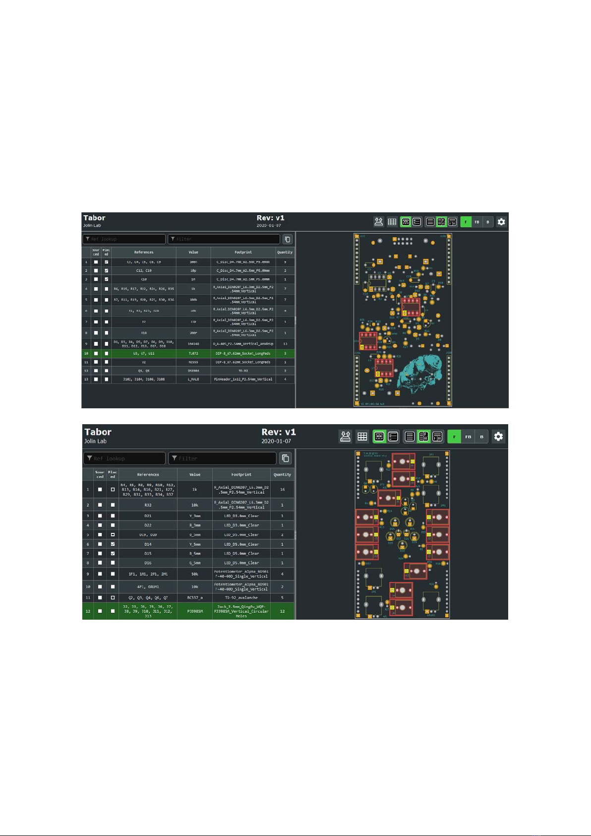
12 J2, J3, J4, J5, J6, J7, J8, J9, J10, J11, J12, J13 PJ398SM
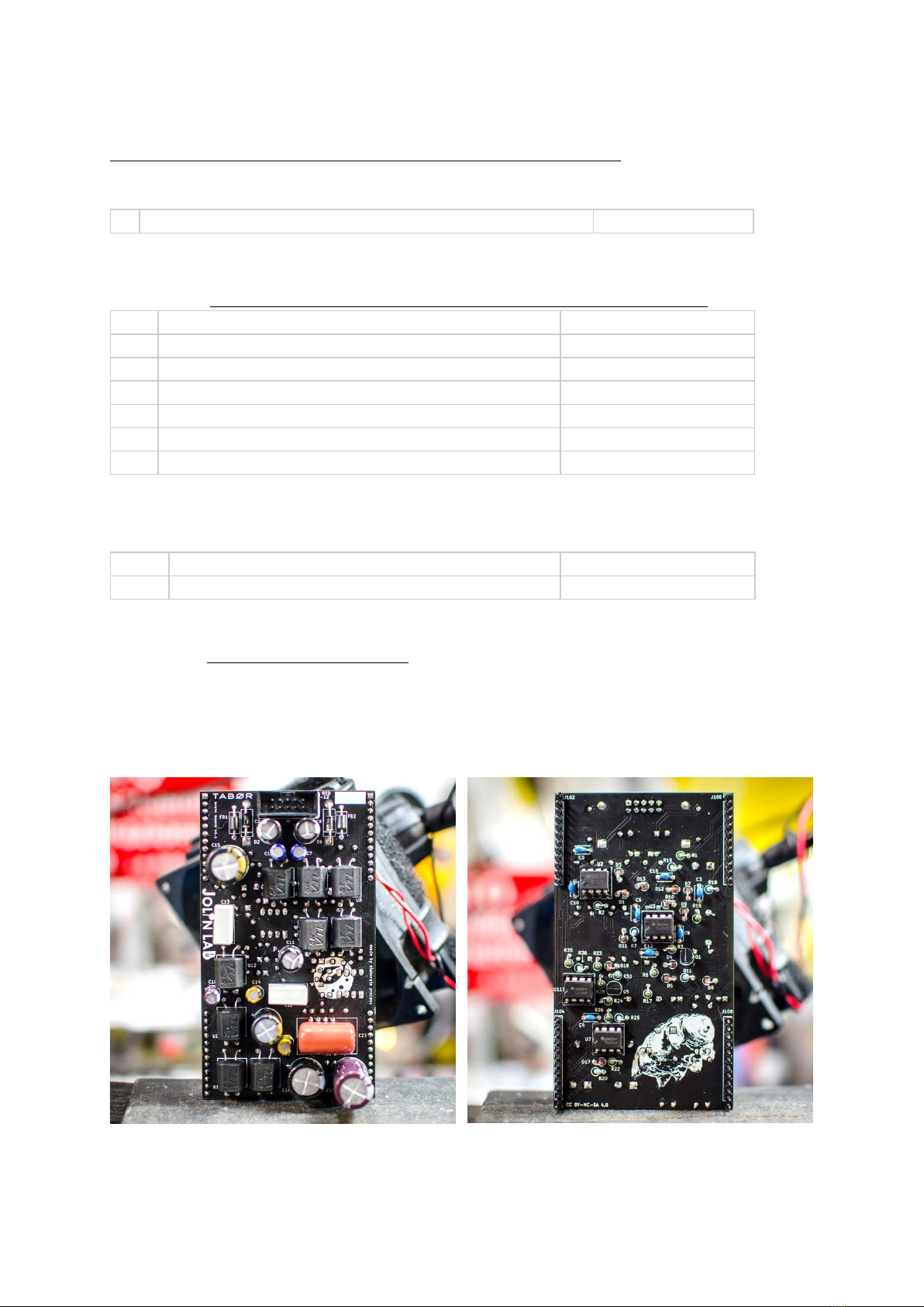
now the other side
female headers:
Always check if you are on the right side of the board by looking at the drawings and texts on the PCB:
the header’s body needs to match the drawing on the PCB.
tip: solder one pin and check if the header row is aligned and perfectly vertical with the PCB.
If so solder all the other pins.
4
J101, J103, J105, J107
FEMALE
At last put the panel on - check its direction - tighten the nuts
Then solder all the surface components.
tip: we are soldering them now to ensure that all the surface components are
aligned with the panel.
Put the knobs on the potentiometers and tight their screws with the key.
check if everything is in place and
you are done with the control board
•Make a sandwich with the two boards considering their direction
•Check the power header for shorts with the multimeter.
tip: follow this tutorial2on that by SynthDiyGuy if you have any doubts.
•Mind the polarity on the header socket on your eurorack case, remember that red line is -12v
BEFORE POWERING UP BE SURE THAT
TABØR POWER SOCKET IS ON TOP
AT THE BACK OF THE MODULE
2https://www.youtube.com/watch?v=qS0SoIiiQCo

8
How to check if the module is working properly?
•Play a bit with the knobs until you are sure that all the 7 LEDs light up correctly
•Blue LEDs are on regardless of the RM input
•All the three outputs are working (play with the knobs if the TR out is silent)
done! enjoy your newborn
TABØR
find us:
web ⇒www.jolinlab.com
Instagram ⇒@jolinlab
Table of contents
Other JOLIN LAB Motherboard manuals