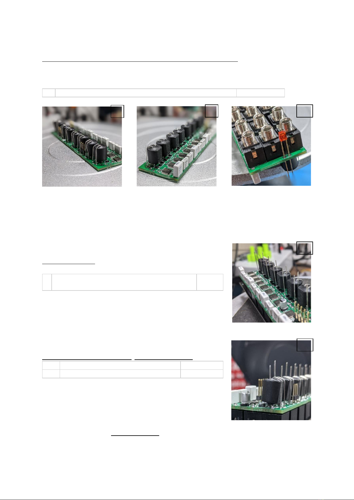
vactrols:
Match the short leg of the vactrol with the squared solder pad on the PCB.
tip: it’s easier to bend at 90° degree all the four legs before trying to fit the vactrol in place.
tip: cut out the lead as close to the board as possible. This will help the jack socket to sit
properly on that side of the board.
U1, U2, U3, U4, U5, U6, U7, U8
ok, now flip the board. we are almost done
jack sockets:
Wait to solder them: just place all of them in the right place and move
to the next step.
J1, J2, J3, J4, J5, J6, J7, J8, J9, J10, J11, J12, J13, J14,
J15, J16, J17, J18, J19, J20, J21, J22, J23, J24
LEDs:
Short leg goes into the square pin. Don’t solder them yet
At last, put the panel on - check its direction - tighten the nuts and then solder all the jacks and LEDs -
the closer to the panel, the more they will be evident on the panel’s hollow line.
tip: we are soldering them now to ensure that all the jack sockets and LEDs are aligned with
the panel. Use a long and thin solder tip to reach the socket pins without damaging the vactrols.