GENERAL SAFETY PRECA
UTIONS
6
–
English
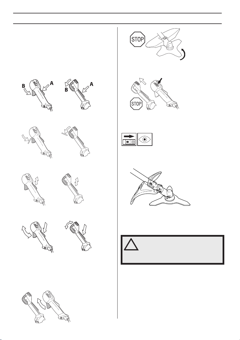
Measures to take bef
ore using
new clearing saws, brushcutters
or trimmers.
•
Please read this manual carefully.
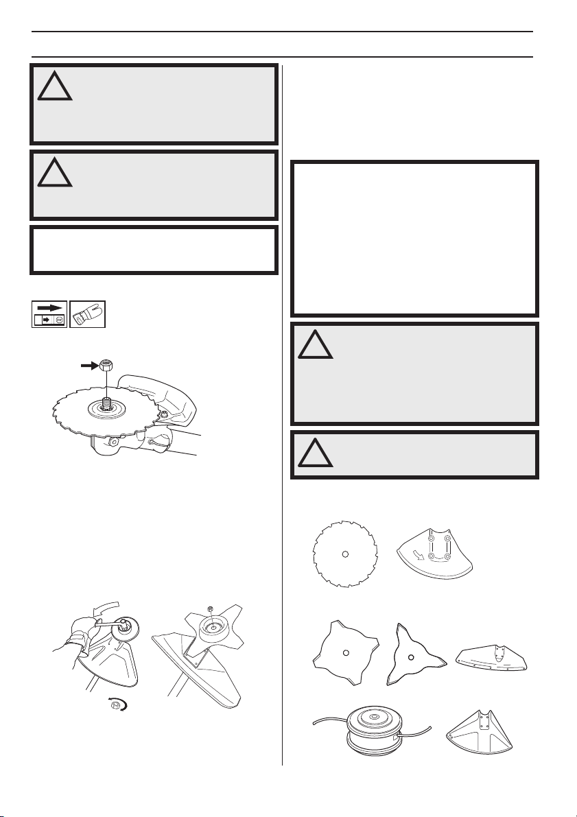
• Check that the locking nut of the cutting equipment is
tighten correctly. See instructions under the heading
Assembly.
Impor
tant
!
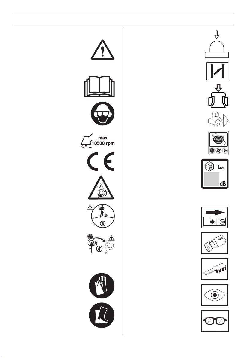
W
ARNING! Long-term exposure to noise
can result in permanent hearing
impairment. Always use approved
hearing protection.
!
W
ARNING! Under no circumstances may
the design of the machine be modified
without the permission of the
manufacturer. Always use original
accessories. Non-authorized
modifications and/or accessories can
result in serious personal injury or the
death of the operator or others.
!
W
ARNING! A clearing saw, brushcutter
or trimmer can be dangerous if used
incorrectly or carelessly, and can cause
serious or fatal injury to the operator or
others. It is extremely important that you
read and understand the contents of this
operator’s manual.
IMPOR
TANT!
The clearing saw or grass trimmer is only designed for
trimming grass, grass clearing and/or forestry clearing.
National or local regulations may regulate the use.
Comply to given regulations.
The only accessories you can operate with this engine
unit are the cutting attachments we recommend in the
chapter on Technical data.
Never use the machine if you are tired, if you have drunk
alcohol, or if you are taking medication that could affect
your vision, your judgement or your co-ordination.
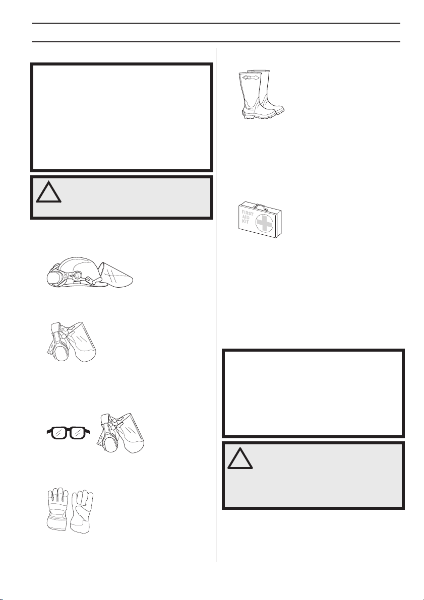
Wear personal protective equipment. See instructions
under the ”Personal protective equipment” heading.
Never use a machine that has been modified in any way
from its original specification.
Never use a machine that is faulty. Carry out the safety
checks, maintenance and service instructions
described in this manual. Some maintenance and
service measures must be carried out by trained and
qualified specialists. See instructions under the
Maintenance heading.
All covers, guards and handles must be fitted before
starting. Ensure that the spark plug cap and ignition
lead are undamaged to avoid the risk of electric shock.
National legislation could regulate the use of this
machine. Find out what legislation is applicable in the
place where you work before you start using the
machine.
The machine operator must ensure that no people or
animals come closer than 15 meters while working.
When several operators are working in the same area
the safety distance should be at least twice the tree
height and no less than 15 meters.
Carry out an overall inspection of the machine before
use. See the maintenance schedule.
W
ARNING! This machine produces an
electromagnetic field during operation.
This field may under some
circumstances interfere with active or
passive medical implants. To reduce the
risk of serious or fatal injury, we
recommend persons with medical
implants to consult their physician and
the medical implant manufacturer before
operating this machine.
W
ARNING! Running an engine in a
confined or badly ventilated area can
result in death due to asphyxiation or
carbon monoxide poisoning.