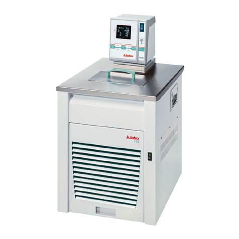
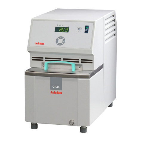
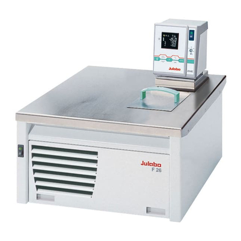
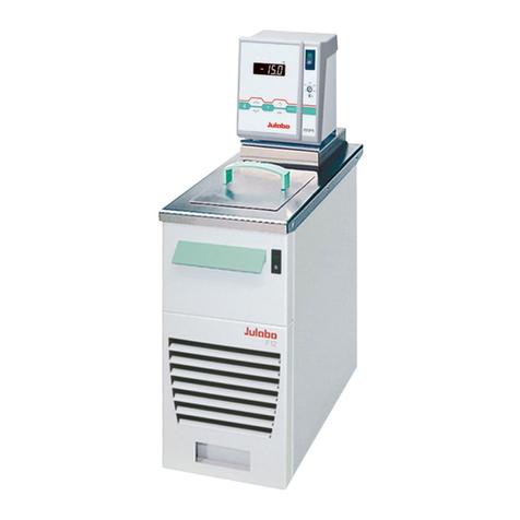
Julabo CORIO CP-200F Installation instructions

Heating immersion circulator, open bath heating circulator,
refrigerated circulator
Original operating manual
1.950.0900.us.V05 12/2022

2
Legal
JULABO USA, Inc.
884 Marcon Boulevard
Allentown, PA 18109
Phone: +1(610) 231-0250
Fax.: +1(610) 231-0260
Info@julabo.us
www.julabo.us
The content of this operating manual is protected by copyright. Information,
including texts, images, and other contents may not be reproduced, distributed,
transmitted, stored or otherwise used in any form without prior explicit written
consent.
Illustrations in this operating manual are for illustrative purposes and are not
necessarily displayed to scale.

3
1Foreword............................................................................................ 6
2About this manual............................................................................. 7
2.1 Original JULABO spare parts ......................................................... 7
2.2 Accessories.................................................................................... 7
2.3 Warnings........................................................................................ 8
2.4 Symbols used................................................................................. 9
3Intended use .................................................................................... 10
4Safety ............................................................................................... 11
4.1 Safety instructions........................................................................ 11
4.2 Safety symbols............................................................................. 13
4.3 Safety function ............................................................................. 14
5Product description ........................................................................ 15
5.1 Product overview.......................................................................... 15
5.2 Function description ..................................................................... 15
5.3 Operating and functional elements............................................... 16
5.3.1 Key description........................................................................ 17
5.4 Interfaces ..................................................................................... 18
5.4.1 RS232 interface ...................................................................... 18
5.4.2 USB-A interface ...................................................................... 19
5.5 Operating interface....................................................................... 20
5.6 Alarm messages........................................................................... 21
5.7 Main menu ................................................................................... 22
5.8 Technical data.............................................................................. 23
5.8.1 Material of parts that come into contact with the medium ....... 25
5.8.2 Technical data for refrigerated circulators ............................... 26
5.8.3 Bath fluids ............................................................................... 32
5.8.4 Hoses...................................................................................... 33
6Transport and installation .............................................................. 34
6.1 Transporting the device................................................................ 34
6.2 Install the device at the operating location ................................... 35
7Initial operation................................................................................ 36
7.1 Mounting the circulator................................................................. 36
7.1.1 Mount heating or refrigerated circulator .................................. 36

4
7.2 Connect the device to the power supply....................................... 37
7.2.1 Connect bridge mounted or heating circulator......................... 37
7.2.2 Connect refrigerated circulator ................................................ 38
7.3 Connecting an external system .................................................... 39
7.3.1 Connect an external system with screw connections .............. 40
7.3.2 Connect an external system with barbed fittings ..................... 42
7.4 Set high temperature safety function............................................ 43
7.5 Fill device ..................................................................................... 44
7.6 Set up power supply for the refrigerated circulator....................... 44
7.7 Adjusting the flow of the bath fluid................................................ 45
7.8 Set chiller mode............................................................................ 46
7.9 Set temperature warning limits..................................................... 46
8Operation ......................................................................................... 48
8.1 Switch on the unit......................................................................... 48
8.2 Switch off the unit......................................................................... 48
8.3 Configuring setpoint temperature ................................................. 48
8.4 Start temperature control application............................................ 49
8.5 Activate autostart function ............................................................ 49
8.6 Record data.................................................................................. 50
8.6.1 Record measurement data...................................................... 50
8.6.2 Reading out blackbox data...................................................... 50
8.7 Adjust pump ................................................................................. 51
8.8 Remote control device.................................................................. 51
8.8.1 Remote control device using USB interface............................ 51
8.8.2 Set RS232 interface parameters ............................................. 52
8.8.3 Remote control device using RS232 interface ........................ 53
8.8.4 Request device status............................................................. 53
8.9 Setting the timer ........................................................................... 54
8.10 Adjusting the temperature sensor (ATC) ...................................... 55
8.10.1 Adjust internal temperature sensor.......................................... 55
8.10.2 Enabling ATC function............................................................. 56
8.11 Device Reset................................................................................ 56
9Maintenance..................................................................................... 57
9.1 Check safety symbols .................................................................. 57
9.2 Check the functionality of high temperature cut-off ...................... 57

5
9.3 Test the low liquid level safety function ........................................ 57
9.4 Replace detachable power cord................................................... 58
9.5 Emptying ...................................................................................... 58
9.6 Clean device ................................................................................ 59
9.7 Device storage ............................................................................. 59
9.8 Technical Service......................................................................... 60
9.9 Warranty....................................................................................... 61
10 Disposal ........................................................................................... 63
10.1 Device disposal ............................................................................ 63
11 Appendix.......................................................................................... 64
11.1 Interface commands..................................................................... 64
11.1.1 IN commands.......................................................................... 65
11.1.2 OUT commands ...................................................................... 66
11.1.3 Status commands ................................................................... 66
11.1.4 Status messages..................................................................... 67
11.2 Alarms and Warnings................................................................... 68
11.3 Error messages in configuration process ..................................... 71

Foreword
6
1 Foreword
Congratulations!
You have made an excellent choice.
JULABO would like to thank you for the trust you have placed in our company
and products.
This operating manual will help you become acquainted with the use of our
units. Read the operating manual carefully. Keep the operating manual handy at
all times.

About this manual
7
2 About this manual
This manual is intended for the equipment specified on the cover page.
NOTE
Observe the safety instructions!
Read the Safety section of this manual before using the equipment for the
first time.
2.1 Original JULABO spare parts
Hassle-free continuous operation and safety also depend on the quality of the
spare parts used.
Only original JULABO spare parts guarantee the highest possible quality and
safety. Original JULABO spare parts are available directly from JULABO or your
specialist dealer.
Please note that JULABO cannot provide a warranty service if non-original
JULABO spare parts are used.
2.2 Accessories
JULABO offers a wide range of accessories for the devices. Accessories are not
described in this manual.
The complete range of accessories for the devices described in this manual can
be found on our website www.julabo.com. Use the Search function on the
website.

About this manual
8
2.3 Warnings
The manual contains warnings to increase safety when using the device.
Warnings must always be observed.
A warning sign displayed in signal color precedes the signal word. The signal
word, highlighted in color, specifies the severity of the hazard.
DANGER
This signal word designates a danger with a high level of risk which, if it not
prevented, will result in death or serious injuries.
WARNING
This signal word designates a danger with a medium level of risk which, if it
not prevented, may result in death or serious injuries.
CAUTION
This signal word designates a danger with a low level of risk which, if it not
prevented, may result in minor to moderate injuries.
NOTE
This signal word designates a possibly harmful situation. If it is not avoided,
the system or objects in its vicinity may be damaged.

About this manual
9
2.4 Symbols used
Various symbols are used throughout this manual to aid reading
comprehension. This list describes the symbols used.
Tools needed for the following approach
Prerequisite to be met for the following procedure
1. Numbered action steps
Interim result for individual action steps
Additional note for individual action steps
Final result of a procedure
<> Terms in angle brackets denote control menu
[] Terms in square brackets denote keys, softkeys and buttons

Intended use
10
3 Intended use
This section defines the purpose of the unit so that the operator can operate the
unit safely and avoid misuse.
JULABO circulators are laboratory devices that are designed for temperature
control applications with liquid media in a bath tank or with a cooling machine.
An external loop circuit can be connected to the pump connectors so that the
temperature of the bath media can be kept constant.
Only use the device if it is in technically perfect condition and only use it in
accordance with its intended use. Be aware of safety issues or hazards and
comply with the operating manual! In particular, always immediately rectify
faults that could impair safety!
The circulators are not suitable for direct temperature control application of
food, other consumables or pharmaceutical or other medical products.
The devices are not suitable for use in an explosive environment.
The devices are not intended for use in living areas. They may cause interference
with radio reception.

Safety
11
4 Safety
4.1 Safety instructions
The unit is built in accordance with state of the art technology and recognized
safety regulations. Despite this, its use may pose a risk to life and limb for the
user or third parties.
Therefore, always read and observe the following safety instructions before
using the product.
Hot surfaces!
The following parts and elements may become hot during operation:
– Bath fluid
– Heating element
– Bath lid
– Bath surface
– Connections for external application
Contact may cause severe burns or scalds to hands and arms, face and limbs.
• Keep sufficient distance from hot surfaces and fluids.
• Wear suitable protective gloves.
Electric shock from electrical system!
Touching damaged live parts can cause severe electric shocks and lead to injury
or even death.
• Have damaged insulation and parts of the electrical system immediately
repaired by JULABO service technicians or a qualified specialist workshop
• Immediately replace damaged power cords
• When connected with a mains plug, this mains plug must always be readily
accessible
Refrigerants are harmful to health!
Refrigerants and their vapors are harmful to health. There is a suffocation risk in
enclosed spaces.
• Do not touch or inhale refrigerants.
• Have damage to the refrigerant cycle repaired only by JULABO service
technicians or qualified specialists.
• If refrigerant leaks, stop the device immediately and ventilate the room
thoroughly.

Safety
12
Natural refrigerants are flammable!
The device contains flammable refrigerants. If there is a leak in the refrigerant
cycle, a flammable concentration may form in the air and ignite or explode. This
can result in serious injury or death.
• Use the required minimum room size for operating the device.
• Do not store any potential sources of ignition near the device.
• If refrigerant leaks, stop the device immediately and ventilate the room
thoroughly.
• Have damage to the refrigerant cycle repaired only by JULABO service
technicians or qualified specialists.
• Have maintenance work performed only by JULABO service technicians or
qualified specialists.
Wear personal protective equipment!
Lacking or unsuitable personal protective equipment increases the risk of health
damage and injury.
Personal protective equipment includes, for example:
– Work gloves
– Safety shoes
- Protective clothing
– Breathing protection
- Hearing protection
– Face and eye protection
• Specify and provide personal protective equipment for the respective
application.
• Use only personal protective equipment that is in good condition and
provides effective protection.
• Adapt personal protective equipment to the person, e.g., by size.
Keep safety symbols legible!
Safety symbols on the unit warn of dangers in hazardous areas and are an
important part of the unit’s safety equipment. Missing safety symbols increase
the risk of injury to persons.
• Clean dirty safety symbols.
• Replace damaged and unrecognizable safety symbols immediately.

Safety
13
Maintenance and repair work!
Improper maintenance and repair work jeopardizes operational safety. This can
result in serious injury or death.
• Only carry out work described in this operating manual. Switch off the unit
and disconnect it from the power supply before carrying out any work.
• All other maintenance and repair work may only be carried out by a JULABO
service technician or a qualified specialist workshop.
4.2 Safety symbols
There are safety symbols included with the device, which should be attached to
the device before initial operation.
Safety
symbols
Description
Warning of a danger zone. Note operating manual
Warning about hot surface
Warning of cold surface
Read operating manual before switching on

Safety
14
4.3 Safety function
Technical protective devices provide for safe operation. If a safety function is
triggered, the operator is alerted with a message on the display and an acoustic
signal.
Adjustable high temperature cut-off
The high temperature cut-off prevents overheating of the heater.
• If the measured temperature rises above the set protective temperature, an
error message is shown on the display. The pump and heater are switched
off. A restart is required.
Overheating protection
The overheating protection prevents overheating of the heater.
• The protective mechanism is triggered when the device recognizes a
temperature difference of more than 20 K between the working
temperature sensor and the safety temperature sensor. Am error message
appears on the display. A restart is required.
Low liquid level protection
A level switch recognizes when the bath fluid fill level in the bath tank is too
low. The device has a two-stage warming system to prevent overheating of the
heater or dry running of the pump.
• The low liquid level warning is triggered when the liquid level in the bath
tank is about half the full level. A warning message appears on the display.
The bath fluid should be topped up.
• The low liquid level alarm is triggered when the float reaches its lower limit
stop. The device switches off the pump and heater. A continuous signal
tone sounds. A warning message appears on the display. A restart is
required.
Productdescription

Product description
15
5 Product description
Productoverview
5.1 Product overview
Circulators can be combined with various baths and cooling machines.
Heating immersion
circulator
Heating circulator Refrigerated circulator
CORIO CP circulator Circulator with closed
stainless steel bath tank.
Example: CORIO CP-BC4 for
temperature control
application in the bath or an
external application
Circulator with cooling
machine.
Example: CORIO CP-300F for
standard temperature
applications
5.2 Function description
This section describes the function of the device.
The circulator can be mounted on any bath tank with a volume up to 50 liters.
The circulators are used for internal and external temperature control, and
depending on the device combination and accessories used can work in a
temperature range between -50°C and +200°C.
When mounted on a bath tank the circulator is a heating circulator, when
combined with a cooling machine it is a refrigerated circulator.

Product description
16
5.3 Operating and functional elements
The following figure shows the operating and functional elements and their
position on the unit.
Fig. 1: Control and function elements
1
Mains switch
2
Heating control LED
3
LED display
4 Alarm control LED
5
Cooling control LED
6
Keypad with display
7
Service key (covered)
8
High temperature cut-off setting
9
Internal/external flow direction setting
10
USB interface, Type B
11 CAN plug for connection with a refrigeration unit
12
Mains fuse, resettable
13
Mains fuse, resettable
14
USB interface, Type A
15
RS232 interface
16
Mains connection

Product description
17
5.3.1 Key description
The device is operated using the key panel. This is used to control all menu
functions and make entries.
Key Function
The [OK] key is used to start a temperature control application or to stop a
running temperature control application.
The [OK] key enables a selected function, opens a menu option, or confirms a
set value.
Use the arrow keys to navigate in the main menu, select a function, or set a
value. Short press for single steps, press and hold for fast counting.
The [MENU] key is used to bring up main menu, to undo an entry, or to jump
back one step in the menu.

Product description
18
5.4 Interfaces
This section describes the electronic interfaces on the device.
For safe operation, the interfaces must be operated according to their
corresponding permissible specifications.
5.4.1 RS232 interface
The RS232 interface is a 9-pin D-Sub socket for connecting the device to a PC.
RS232 plug
RS232 interface pin assignment
Pin 2 RxD receive data Pin 7 RTS request to send
Pin 3 TxD transmit data Pin 8 CTS clear to send
Pin 5 0 V signal GND
Pins 1, 4, 6 and 9 are reserved. Do not use.
RS232 interface factory setting
Parity straight
Baud rate 4800 baud
Handshake Hardware
Data bit 7
Stop bit 1

Product description
19
5.4.2 USB-A interface
USB sticks can be connected to the USB-A interface. This unit is capable of
reading data from the USB stick as well as saving data to the USB stick.
Technical data for USB-A interface
Output voltage
5 VDC
Maximum current 500 mA

Product description
20
5.5 Operating interface
The device is operated using the four navigation keys. The figure shows the
menu structure of the user interface.
Menu structure
This manual suits for next models
11
Table of contents
Other Julabo Fan manuals
Popular Fan manuals by other brands

Parrot Uncle
Parrot Uncle F8306 Installation & operating instructions

Craftmade
Craftmade MO56 instruction manual

Hunter
Hunter 20552 Owner's guide and installation manual

SHURflo
SHURflo Comfort Air 21-1316-00 Installation and operation manual

Geek
Geek GF5 quick start guide

Vortice
Vortice LINEO 100 QUIET Instruction booklet