Julabo AWC100 User manual

Operating Manual
Compact Recirculating Cooler AWC100
Compact Recirculating Cooler
AWC 100
1.951.4820-V4 07/2019 Project 1265
JULABO GmbH
77960 Seelbach/Germany
Tel: +49 7823 51-0
Fax: +49 7823 24-911

Imprint
JULABO GmbH
Gerhard-Juchheim-Strasse 1
77960 Seelbach/Germany
Tel: +49 782351-0
Fax: +49 78232491
www.julabo.com
The contents of this operating manual are protected by copyright.
Information, including text, images, and other content, may not be
reproduced, distributed, transferred, stored, forwarded, or used in any other
form without prior written, explicit authorization.
Figures in this operating manual are for illustration purposes only and are
not necessarily to scale.
The rights to the operating manual and its contents lie exclusively with
JULABO GmbH.

Table of contents
1Foreword ......................................................................................................................................................4
2Intended use ................................................................................................................................................5
3Warnings ......................................................................................................................................................6
4Symbols used ..............................................................................................................................................7
5Responsibilities of the operating company..............................................................................................7
5.1 General safety instructions, operating company......................................................................................7
5.2 General safety instructions, operator .......................................................................................................7
6Description...................................................................................................................................................9
6.1 Operating and functional elements ..........................................................................................................9
6.2 Technical data ........................................................................................................................................10
6.3 Bath fluids...............................................................................................................................................11
6.4 Recommended hoses ............................................................................................................................11
7Operation....................................................................................................................................................12
7.1 Transport ................................................................................................................................................12
7.2 Initial operation .......................................................................................................................................12
7.3 Operation................................................................................................................................................13
7.4 Emptying.................................................................................................................................................13
7.5 Maintenance...........................................................................................................................................14
7.6 Technical Service ...................................................................................................................................15
7.7 Sending a unit ........................................................................................................................................15
7.8 Disposal..................................................................................................................................................15
8Declaration of Conformity ........................................................................................................................16

Foreword
4
1 Foreword
Congratulations!
You have made an excellent choice.
JULABO would like to thank you for the trust you have placed in our company and
products.
This operating manual will help you become acquainted with the use of our units.
Read the operating manual carefully. Keep the operating manual handy at all
times.
If you have any questions regarding the operation of the unit or the operating
manuals, please call us or send us an e-mail or fax.
Contact:
JULABO GmbH
Gerhard-Juchheim-Strasse 1
77960 Seelbach/Germany
Tel. +49 782351-0
Fax +49 7823249
www.julabo.com

Intended use
5
2 Intended use
This section defines the purpose of the unit so that the operator can operate the
unit safely and avoid misuse.
Recirculating coolers are designed for temperature control of liquid media. An
external cooling circuit is connected to the connections, using which media can be
constantly cooled.
The recirculating coolers are not suitable for direct temperature control of food or
other items intended for human consumption, pharmaceutical products, or medical
products. Direct temperature control means an unprotected contact of the material
to be temperature-controlled with the bath fluid.
The units are not suitable for use in a potentially explosive environment.
Any other uses not listed here are not considered as intended.

Warnings
6
3 Warnings
The operating manual contains warnings intended to increase safety when
handling the unit. The general warning sign, consisting of an isosceles triangle
enclosing an exclamation mark and displayed in signal colours, precedes the
signal words. The meaning of the danger is classified in conjunction with a signal
word.
CAUTION
The signal word indicates a hazard with a low degree of risk which, if not avoided, may
result in minor to moderate injury.
WARNING
The signal word indicates a hazard with a medium degree of risk which, if not avoided,
may result in death or serious injury.
DANGER
The signal word indicates a hazard with a high degree of risk which, if not avoided, will
result in death or serious injury.
NOTE
The signal word indicates a potentially harmful situation. If it is not avoided, the system
or objects in its vicinity may be damaged.

Symbols used
7
4 Symbols used
Symbols are used as additional structural elements in various places in the
manual.
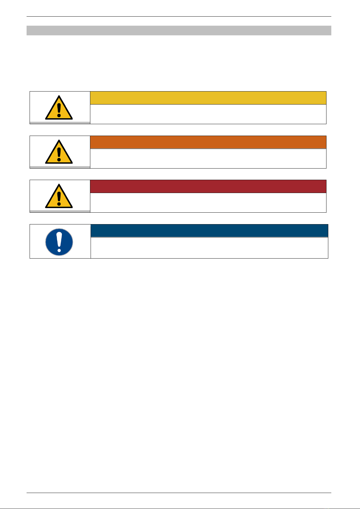
The list describes the symbols used in the manual:
Tool required for a following procedure
Prerequisite for the following procedure
1. Action steps are numbered consecutively
The symbol shows an intermediate result for individual action steps
The symbol shows the final result of a procedure
5 Responsibilities of the operating company
It is the responsibility of the operating company to ensure that the safety
instructions described in this operating manual are observed.
5.1 General safety instructions, operating company
The products of JULABO GmbH are safe when installed, operated, and
maintained according to the generally accepted rules of safety. This chapter
explains the potential hazards that can arise in conjunction with operation of the
recirculating cooler and describes the most important safety measures for
eliminating these hazards when possible.
• The operating company is responsible for the qualifications of the operating
personnel.
• The operating company ensures that the operating personnel have been
instructed in the handling of the recirculating cooler.
• The operators must be trained on a regular basis on the hazards that occur
during their activities and on measures for mitigating these hazards.
• The operating company must ensure that the persons entrusted with
operation, installation and maintenance have read and understood the
operating manual.
• When using hazardous materials or substances that may become hazardous,
only persons qualified to handle these substances and the recirculating cooler
may operate the recirculating cooler.
5.2 General safety instructions, operator
It is important that you follow all safety instructions in order to avoid personal injury
and property damage. These instructions supplement workplace safety
regulations.
• The unit may be connected to protected earth (PE) mains power outlets only
• The mains plug serves as a safe protective separation from the power supply
network and must always be freely accessible
• Do not attempt to use the unit if the mains cable is damaged
• Install the unit on an even surface on a supporting layer made of non-
combustible material
• Be sure to read the operating manual before initial operation

Responsibilities of the operating company
8
• Use tubing suitable for temperature control purposes
• Secure hose connections against slipping
• Avoid kinking the tubing
• Regularly check tubing for material fatigue, such as cracks
• Never put a damaged or leaking unit into operation
• Before performing service or repair tasks or transporting the unit, switch the
unit off and remove the power plug from the socket
• Completely drain the unit before transporting it
• Switch off the unit and disconnect the mains plug before carrying out any
cleaning work
• Transport the unit carefully
• Shaking or falls may damage the inside of the unit
• Observe safety labels
• Do not remove safety labels
• Service and repairs may be performed by authorised expert personnel only

Description
9
6 Description
The recirculating cooler AWC 100 can be used as a cooling unit for water in closed
circuits.
A pump delivers the cooling water via the cooling water outlet into the external
circuit and cools the connected application. The cooling water flows back into the
recirculating cooler via the cooling water inlet. Heat is permanently extracted from
the flowing liquid in the recirculating cooler. The water temperature depends on
the ambient temperature and must not exceed 40 °C.
6.1 Operating and functional elements
The following figure shows the operating and functional elements and their
position on the unit.
Fig. 1: Operating and functional elements
1
Handle
2
Cooling water reservoir cover
3
Hose connection, cooling water inlet
4
Cooling capacity two-way switch
5
Hose connection, cooling water outlet
6
Level indicator, cooling water reservoir, min/max
7
Mains switch

Description
10
8
Fuse
9
Mains connection
6.2 Technical data
The table contains the technical data of the unit. It refers to the rated voltage and
rated frequency as well as to an ambient temperature of 20°C.
Technical data
Working temperature range
°C
+20 … +40
Cooling capacity depending on the temperature
differential between the return line and ambient
temperature
°C
20
15
10
5
Stage 0
W
400
320
220
120
Stage 1
W
550
440
300
180
Circulating pump
Flow rate, max.
Pressure, max.
l/min
bar
3.5
0.49
Sound level at 1 m distance
db (A)
55
Filling volume, reservoir
l
0.9
Dimensions (WxHxD)
cm
20x34x30
Protection class according to EN 60 529
IP 21
Permissible ambient temperature range
°C
5 … 40
Weight
kg
11
Mains connection
V/Hz
100 …230/50-60
Current consumption (230 V)
A
1
Environmental conditions according to IEC 61 010-1:
•For indoor use only
•Up to 2000 m above sea level
•Ambient temperature +5 … +40 °C
•Maximum relative humidity 80 % for temperatures up to 31 °C, decreasing
linearly to 50 % relative humidity at a temperature of 40 °C
•Permissible voltage deviation ±10 %

Description
11
6.3 Bath fluids
JULABO recommends suitable bath fluids that ensure a long life-time of the unit.
NOTE
JULABO assumes no liability if non-approved bath fluids are used!
Unsuitable, non-approved bath fluids can damage the unit.
• Only water is permitted as bath fluid
• JULABO recommends a water mixture of 70 % softened/decalcified water and 30 %
tap water
• Consult with JULABO before using a bath fluid other than the recommended bath
fluids
The unit is suitable for the following bath fluids:
• Softened/decalcified water, temperature range +5 … +80 °C
Please note when using bath fluids:
• Due to its high lime content, hard water is not suitable as a bath fluid as it can
lead to premature calcification of the unit
• Water containing iron can lead to the formation of rust, even on stainless steel
components
• Chlorinated water can lead to pitting corrosion
• Distilled and deionised water can also lead to corrosion of stainless steel
components
6.4 Recommended hoses
The hoses listed in the table are recommended for the unit. These can be ordered
from JULABO.
Order number
Designation
Inner diameter
8930008
1 m CR hose
8 mm
8930010
1 m CR hose
10 mm

Operation
12
7 Operation
7.1 Transport
This section describes how to transport the unit safely.
CAUTION
Risk of injury due to the unit tipping over!
An unsecured unit may tip over during transport and cause injury.
• Secure the unit against tipping over and falling during transport
• Secure loose parts against falling during transport
• Transport the unit in an upright position using a suitable means of transport
The unit is switched off and drained.
A suitable transport trolley is ready.
1. Disconnect the mains plug of the unit.
2. Close the cooling water reservoir using the cover.
3. Place the unit upright and centrally on the transport trolley.
4. Secure the unit on the transport trolley against tipping over.
5. Place loose parts, such as cables, with the unit on the transport trolley.
The unit is ready for transport.
7.2 Initial operation
This section describes how to put the unit into operation.
NOTE
Secure hose connections against slipping!
If the hose connections are installed incorrectly, they may leak or slip off the
connection pieces.
• Secure the hose connections against slipping off
• After initial operation, check all hose connections for leaks
NOTE
Do not exceed the maximum filling level in the cooling water reservoir!
The maximum fill level in the cooling water reservoir must not be exceeded. When the
unit is switched off, excess water can flow back from the external application and
overflow.
• When switching off the unit, prevent the water from flowing back from the external
application
• Insert a stopcock or hose clamp into the external circuit
The unit is unpacked.
1. Place the unit on a horizontal and firm surface.
For good ventilation and heat emission, a distance of at least 20 cm from the
wall and adjacent equipment must be maintained.
2. Connect the unit with the mains plug to a mains power outlet.
3. Connect the hoses of the external application to be cooled to the connections
of the unit.

Operation
13
4. Remove the cover of the cooling water reservoir.
5. Fill the cooling water reservoir with water up to the maximum mark.
6. Close the cooling water reservoir using the cover.
7. Switch unit on at the mains switch.
The pump starts to pump the water through the condenser and the external
application.
8. Observe the level in the cooling water reservoir and top up with water when
the level reaches the minimum mark.
The level should always be between the minimum and maximum marks during
operation.
The unit is ready for operation.
7.3 Operation
The recirculating cooler is very user-friendly. If it is connected to an external
application, it is sufficient to switch it on. No settings are required. The recirculating
cooler is designed for continuous operation under normal conditions.
The unit is ready for operation and connected to the external application.
The two-way switch for the cooling capacity is set to stage 0.
1. Switch unit on at the mains switch.
The pump starts to pump the water through the condenser and the external
application. The lower ventilator is active.
2. If you need a higher cooling capacity, switch the cooling capacity two-way
switch to stage 1.
The second ventilator is switched on.
The unit is in operation.
7.4 Emptying
If the unit is to be sent to Technical Service or disposed of properly, it must be
completely emptied.
In general, the unit should be completely emptied before any extended shutdown
and when changing the external application.
The unit is switched off.
The external application is disconnected from the unit.
1. Disconnect the mains plug of the unit.
2. Remove the cover of the cooling water reservoir.
3. Provide a sufficiently large collecting vessel.
4. Tilt the unit quickly forwards over the collecting vessel.
The water flows from the cooling water reservoir into the collection vessel
provided.
5. When the cooling water reservoir is completely empty, close it with the cover.
The unit is emptied.

Operation
14
7.5 Maintenance
The recirculating cooler is maintenance-free. If the cooling capacity decreases, it is
sufficient to clean it. Proceed as described below.
NOTE
Property damage due to service and repair work not carried out by an expert!
Service and repair work carried out by unauthorised persons may result in damage to
the unit.
• Service and repair work may only be performed by qualified electricians
• JULABO accepts no liability for property damage caused by service and repair work
not carried out by authorised specialist personnel
Torx bit, size T20
Bit holder
The unit is switched off.
1. Disconnect the external application from the unit.
2. Empty the unit.
3. Remove four fastening screws each on the left and right side of the unit
[arrows, left figure].
4. Carefully remove the hood upwards and disconnect the earthing cable [arrow,
right figure].
5. Use a vacuum cleaner to carefully remove dust and dirt from the inside of the
unit.
6. Position the hood and connect the earthing cable [arrow, right figure].
7. Mount the hood with the fastening screws.
8. Clean the unit surface with a lint-free cloth and a mild cleaning agent.
9. Vacuum the vents.
The unit is cleaned.

Operation
15
7.6 Technical Service
If the unit shows faults you cannot resolve, please contact our Technical Service.
JULABO GmbH
Technical Service
Gerhard-Juchheim-Strasse 1
77960 Seelbach/Germany
Tel. +49 782351-66
Fax +49 782351-99
www.julabo.com/support
7.7 Sending a unit
After consulting with our Technical Service, the unit can be returned. The unit must
be prepared accordingly for shipment.
1. Empty the unit completely.
2. Close all connections tightly with nuts and plugs.
3. Pack the unit carefully and protect it from damage.
4. Mark the packaging for an upright transport of the unit.
5. Complete the online return form at www.julabo.com/support.
The unit is ready for shipment and can be sent to JULABO Technical Service.
7.8 Disposal
When disposing the unit, the usual country-specific guidelines must be observed.
1. Empty the unit completely.
2. Contact an authorised disposal company for disposal of the unit.
It is not permissible to dispose of the unit in household waste or similar
facilities intended for collecting household waste.
The unit can be disposed of properly.

Declaration of Conformity
16
8 Declaration of Conformity
Other manuals for AWC100
4
Table of contents
Other Julabo Freezer manuals
Popular Freezer manuals by other brands

CDA
CDA FW482 Manual for installation, use and maintenance

Sandstrom
Sandstrom SUF60W13E instruction manual

Helmer Scientific
Helmer Scientific iLF120 Service and maintenance manual

Frigidaire
Frigidaire FFC0522FW9 Use & care manual

Electrolux
Electrolux ENT8TE18S3 user manual

Bosch
Bosch KFN86 Series Installation instructions and instructions for use