Julabo F7006 User manual

19514828-V2.doc Print date: 08.10.2013
English
Operating manual
Recirculating Coolers
FL7006 FLW7006
FL11006 FLW11006
RS232
A
LARM
°C
FL7006
1.951.4828-V2 10/13
JULABO GmbH
77960 Seelbach / Germany
Tel. +49 (0) 7823 / 51-0
Fax +49 (0) 7823 / 24 91
www.julabo.de

2
Congratulations!
You have made an excellent choice.
JULABO thanks you for the trust you have placed in us.
This operating manual has been designed to help you gain an understanding of the operation and
possible applications of our circulators. For optimal utilization of all functions, we recommend that you
thoroughly study this manual prior to beginning operation.
The JULABO Quality Management System
Temperature control devices for research and industry are developed,
produced, and distributed according to the requirements of ISO 9001 and
ISO 14001. Certificate Registration No. 01 100044846
Unpacking and inspecting
Unpack the recirculating cooler and accessories and check for damages
incurred during transit. These should be reported to the responsible carrier,
railway, or postal authority, and a request for a damage report should be
made. These instructions must be followed fully for us to guarantee our full
support of your claim for protecting against loss from concealed damage. The
form required for filing such a claim will be provided by the carrier.
Lifting device for transportation by crane see page 18
Printed in Germany Changes without prior notification reserved
Important: keep operating manual for future use

3
TABLE OF CONTENTS
1. Intended use................................................................................................................................. 4
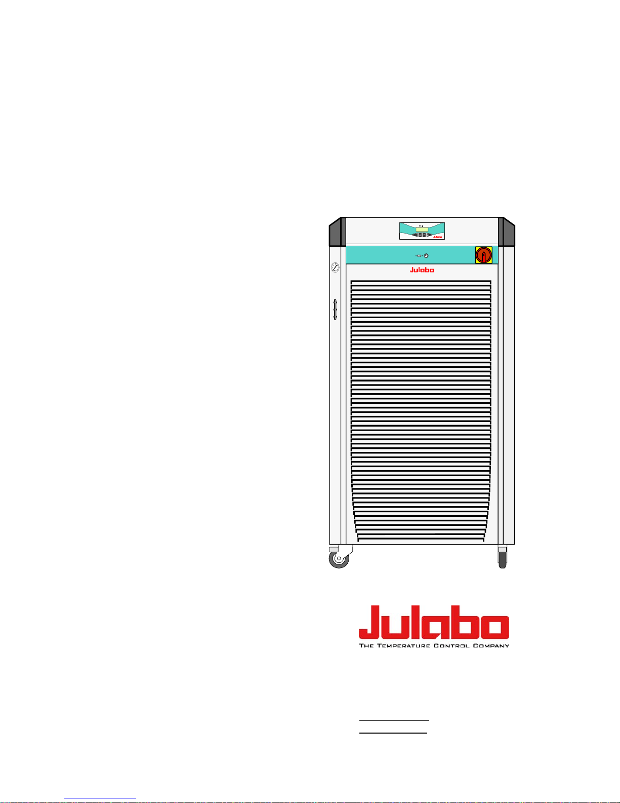
1.1. Description........................................................................................................................ 4
2. Operator responsibility – Safety instructions................................................................................ 4
2.1. Disposal............................................................................................................................ 6
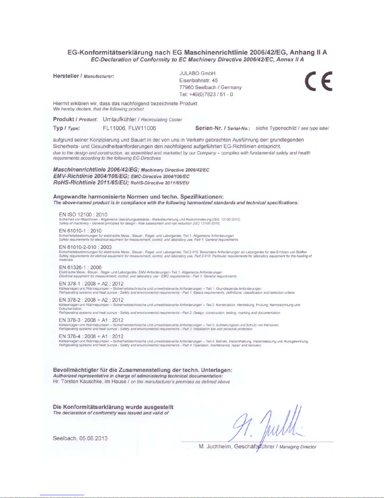
2.2. EC Conformity................................................................................................................... 7
3. Technical specifications................................................................................................................ 9
3.1. Cooling water connection................................................................................................ 12
4. Safety notes for the user ............................................................................................................ 13
4.1. Explanation of safety notes............................................................................................. 13
4.2. Explanation of other notes.............................................................................................. 13
4.3. Safety instructions........................................................................................................... 13
5. Installation .................................................................................................................................. 15
5.1. Tubing............................................................................................................................. 17
6. Operating controls and functional elements............................................................................... 18
7. Operating procedures................................................................................................................. 20
7.1. Bath fluids....................................................................................................................... 20
7.2. Power connection ........................................................................................................... 20
7.3. Filling............................................................................................................................... 21
7.4. Switching on / Start - Stop .............................................................................................. 21
7.5. Setting the feed pressure................................................................................................ 22
7.6. Setting the temperatures
................................................................................................. 22
7.7. AUTOSTART ON / OFF.................................................................................................. 22
7.8. Remote control: activate – deactivate............................................................................. 23
8. Safety installations...................................................................................................................... 24
8.1. Excess temperature protection....................................................................................... 24
8.2. Low level protection........................................................................................................ 24
9. Troubleshooting guide / Error messages.................................................................................... 24
10. Electrical connections ....................................................................................................... 26
11. Remote control.................................................................................................................. 27
11.1. Setup for remote control ................................................................................................. 27
11.2. Communication with a PC or a superordinated data system.......................................... 27
11.3. List of commands............................................................................................................ 28
11.4. Status messages ............................................................................................................ 28
11.5. Error messages............................................................................................................... 29
12. Cleaning / repairing the unit.............................................................................................. 30
12.1. JULABO Service – Online remote diagnosis.................................................................. 32
12.2. Draining........................................................................................................................... 33
13. Adequate storing of operating manual.............................................................................. 33
14. Warranty conditions .......................................................................................................... 34

4
1. Intended use
JULABO recirculating coolers have been designed for temperature application to specific fluids. The
pump connections can be used for cooling applications in an external circuit at a constant temperature.
JULABO water baths are not suitable for direct temperature control of foods, semi-
luxury foods and tobacco, or pharmaceutical and medical products. Direct temperature
control means unprotected contact of the object with the bath medium (bath fluid).
1.1. Description
PID1
RS232
The recirculating coolers are operated via the splash-proof keypad. The
implemented microprocessor technology allows to set and to store the setpoint that
can be indicated on the LED temperature display.
The PID temperature regulation is used to withdraw heat from the bath fluid by
means of the cooling machine and to automatically regulate the required need.
Electrical connections:
1. The serial interface RS232 allows modern process technology without
additional interface.
2. Alarm output for external alarm message.
Manually adjustable by-pass (handwheel) to reduce the pump capacity
(e. g. for glass equipment).
2. Operator responsibility – Safety instructions
The products of JULABO ensure safe operation when installed, operated, and maintained according to
common safety regulations. This section explains the potential dangers that may arise when operating
the circulator and also specifies the most important safety precautions to preclude these dangers as
far as possible.
The operator is responsible for the qualification of the personnel operating the units.
The personnel operating the units should be regularly instructed about the dangers involved with
their job activities as well as measures to avert these dangers.
Make sure all persons tasked with operating, installing, and maintaining the unit have read and
understand the safety information and operating instructions.
When using hazardous materials or materials that could become hazardous, the unit may be
operated only by persons who are absolutely familiar with these materials and the unit. These
persons must be fully aware of possible risks.
If you have any questions concerning the operation of your unit or the information in this manual,
please contact us!
Contact JULABO GmbH
Eisenbahnstraße 45
77960 Seelbach / Germany
Fax +49 7823 2491 www.julabo.de

5
Safety recommendations for the operator
You received a product conceived for industrial use. Nevertheless, avoid strikes to the housing,
vibrations, damages to the keypad foil (keys, display) or contamination.
Make sure the product is regularly checked for proper condition. Regularly check (at least every
2 years) the proper condition of the mandatory, warning, prohibition and safety labels.
Take care that the mains supply features a low impedance to avoid any negative affects on the
instrument being operated in the same mains.
This unit is designed for operation in a controlled electromagnetic environment. This means that
transmitting devices (e.g. cellular phones) should not be used in the immediate vicinity. Magnetic
radiation may influence other units with components susceptible to magnetic fields (e.g. a
monitor). We recommend to keep a minimum distance of 1 m.
Permissible ambient temperature: max. 40 °C, min. 5 °C.
Permissible relative air humidity: 50 % (40 °C).
Do not store in an aggressive atmosphere. Protect from contaminations.
Do not expose to sunlight.
Appropriate Operation
Only qualified personnel is authorized to perform configuration, installation, maintenance and repairs
of the water bath.
Routine operation can also be carried out by untrained personnel who should however be instructed
by trained personnel.
Use
For the use according to the intended purpose, special material requirements have to be respected
(bath fluids). Only use non-acid and non corroding materials.
Observe all warnings for the used materials (bath fluids) and the respective instructions (safety data
sheets).
Only use the unit in well ventilated areas. (see page 15).
The recirculating coolers are not for use in explosive atmosphere
When using hazardous materials or materials that could become hazardous, the operator must affix
the enclosed safety labels (1 + 2) to the front of the unit so they are highly visible:
1
Warning label W00: Colors: yellow, black
Danger area. Attention! Observe instructions.
(operating manual, safety data sheet)
2
or
Mandatory label M018: Colors: blue, white
Carefully read the user information prior to beginning operation.
Scope: EU
2
Semi S1-0701 Table A1-2 #9
Carefully read the user information prior to beginning operation.
Scope: USA, NAFTA
Observe the instructions in the manuals for instruments of a different make that you connect to the
circulator, particularly the corresponding safety instructions. Also observe the pin assignment of plugs
and technical specifications of the products.

6
2.1. Disposal
This unit contains the refrigerant R404A, which at this time is not considered harmful to the ozone
layer. However, over the long operating period of the unit, disposal rules may change. Therefore, only
qualified personnel should handle the disposal.
Valid in EU countries
See the current official journal of the European Union – WEEE directive.
Directive of the European Parliament and of the Council on waste electrical and
electronic equipment (WEEE).
This directive requires electrical and electronic equipment marked with a crossed-
out trash can to be disposed of separately in an environmentally friendly manner.
Contact an authorized waste management company in your country.
Disposal with household waste (unsorted waste) or similar collections of municipal
waste is not permitted!

7
2.2. EC Conformity

8

9
3. Technical specifications
Recirculating Cooler
Cooling FL7006 FLW7006
air cooled water cooled
Working temperature range °C -20 ... +40 -20 ... +40
Temperature stability °C ±0.5
Temperature selection: digital
via key pad indication on LED-DISPLAY
remote control via personal computer indication on monitor
Temperature indication: LED-DISPLAY
Resolution °C 0.1
Temperature control PID 1
Temperature sensor Pt 100
Excess temperature protection 85 °C - fixed value
Low liquid level protection float switch
Cooling capacity
Medium: Mixture water-glycol °C
kW +20 0 -10 +20 0 -10
7.0 5.1 3.0 7.4 5.5 3.1
Cooling compressor 1-stage
Refrigerant R404A
Electrical connections:
Computer interface RS232
Alarm output for external alarm signal
Circulating pump:
discharge, max. at 0 bar l/min 60 60
pressure, adjustable at 0 Liter bar 0.5 ... 6.0 0.5 ... 6.0
Feed pressure indication bar Manometer
Filling level indicator sight glass
Filling volume from ... to liters 39 ... 47
Dimensions (WxLxH) cm 78x85x148
Weight kg 252 220
Ambient temperature range °C 5 ... 40
Return flow temperature °C 80 max.
Cooling water
Flow rate at 20 °C inlet temperature
l/min
----- 11.6
IP class according to IEC 60 529 IP 21
Mains power connection 400 V/3PNPE/50Hz V/ Hz 360-440/3PNPE/50 360-440/3PNPE/50
Current input at 230 V A 14 14
Mains power connection 230 V/3PPE/60Hz V/ Hz 197-242/3PPE/60 207-253/3PPE/60
Current input at 220 V A 23 ------
All measurements have been carried out at: rated voltage and frequency,
ambient temperature: 20 °C

10
Recirculating Cooler
Cooling FL11006 FLW11006
air cooled water cooled
Working temperature range °C -20 ... +40 -20 ... +40
Temperature stability °C ±0.5
Temperature selection: digital
via key pad indication on LED-DISPLAY
remote control via personal computer indication on monitor
Temperature indication: LED-DISPLAY
Resolution °C 0.1
Temperature control PID 1
Temperature sensor Pt 100
Excess temperature protection 85 °C - fixed value
Low liquid level protection float switch
Cooling capacity
Medium: Mixture water-glycol °C
kW +20 0 -10 +20 0 -10
11.0 7.5 5.0 11.5 7.3 4.8
Cooling compressor 1-stage
Refrigerant R404A
Electrical connections:
Computer interface RS232
Alarm output for external alarm signal
Circulating pump:
discharge, max. at 0 bar l/min 60 60
pressure, adjustable at 0 Liter bar 0.5 ... 6.0 0.5 ... 6.0
Feed pressure indication bar Manometer
Filling level indicator sight glass
Filling volume from ... to liters 39 ... 47
Dimensions (WxLxH) cm 78x85x148
Weight kg 248 250
Ambient temperature range °C 5 ... 40
Return flow temperature °C 80 max.
Cooling water
Flow rate at 20 °C inlet temperature
l/min
----- 18.2
IP class according to IEC 60 529 IP 21
Mains power connection 400 V/3PNPE/50Hz V/ Hz 360-440/3PNPE/50 360-440/3PNPE/50
Current input at 230 V A 17 17
Mains power connection 230 V/3PPE/60Hz V/ Hz 207-253/3PPE/60 207-253/3PPE/60
Current input at 230 V A 27 ------
All measurements have been carried out at: rated voltage and frequency,
ambient temperature: 20 °C

11
Warning functions and safety installations
Excess temperature protection 85 °C - fixed value
Low liquid level protection float switch
Alarm message optical + audible (permanent)
Excess temperature - Warning function 75 °C
Overload protection for compressor and pump motor
Classification according to DIN 12876-1 class I
Environmental conditions according to IEC 61 010-1:
Use only indoor.
Altitude up to 2000 m - normal zero.
Ambient temperature: +5 ... +40 °C
Air humidity:
Max. rel. humidity 80 % for temperatures up to +31 °C,
linear decrease down to 50 % relative humidity at a temperature of +40 °C
Max. mains fluctuations of ±10 % are permissible.
The unit corresponds to Class I
Overvoltage category II
Pollution degree 2
Caution:
The unit is not for use in explosive atmosphere
Standards for interference resistance according to EN 61326-1
This unit is an ISM device classified in Group 1 (using high frequency for internal purposes) Class A
(industrial and commercial range).

12
3.1. Cooling water connection
Only for water cooled models - FLW:
Cooling water pressure (IN / OUT ) max. 6 bar
Difference pressure (IN - OUT ) 2 bar to 6 bar
Flow rate on FLW 7006 typical 11.6 l/min
Flow rate on FLW 11006 typical 18.2 l/min
Cooling water temperature <20 °C
Notice: Cooling water circuit
Risk of oil leaking from the refrigeration system (compressor) of the recirculating
cooler into the cooling water in case of a fault in the cooling water circuit!
Observe the laws and regulations of the water distribution company valid in the
location where the unit is operated.
Recommended quality of cooling water:
pH – value 7.5 to 9.0
Sulfate [SO4 2- ] < 100 ppm
Hydrocarbonate [HCO3- ] / Sulphate [SO4 2-] > 1 ppm
Hardness [Ca2+, Mg2+] / [HCO3-] > 0.5 dH
Alkalinity 60 ppm < [HCO3-] < 300 ppm
Conductivity < 500 μs / cm
Chloride (CL-) < 50 ppm
Phosphate (PO43-) < 2 ppm
Ammonia (NH3) < 0.5 ppm
Free Chlorine < 0.5 ppm
Ferri Ions (Fe3+ ) < 0.5 ppm
Mangano Ions (Mn2+) < 0.05 ppm
Carbon dioxide (CO2) < 10 ppm
Hydrosulfide (H2S) < 50 ppm
Content of oxygen < 0.1 ppm
Algae growth impermissible
Suspended solids impermissible
Notice:
Danger of corrosion of heat exchanger due to unsuitable quality of cooling
water.
Due to its high content of lime hart water is not suitable for cooling and causes
calcination of the heat exchanger.
Ferrous water or water containing ferrous particles will cause formation of rust
even in heat exchangers made of stainless steel.
Chlorous water will cause pitting corrosion in heat exchangers made of stainless
steel.
Due to its corrosive characteristics distilled and deionized water is unsuitable and
will cause corrosion of the bath.
Due to its corrosive characteristics sea water is not suitable.
Due to its microbiological (bacteria) components which settle in the heat
exchanger untreated and unpurified river water and water from cooling towers is
unsuitable.
Avoid particulate matter in cooling water.
Avoid putrid water.

13
4. Safety notes for the user
4.1. Explanation of safety notes
In addition to the safety warnings listed above, warnings are posted throughout the
manual. These warnings are designated by an exclamation mark inside an equilateral
triangle. “Warning of a dangerous situation (Attention! Please follow the
documentation).”
The danger is classified using a signal word.
Read and follow these important instructions.
Warning:
Describes a possibly highly dangerous situation. If these instructions are not followed,
serious injury and danger to life could result.
Caution:
Describes a possibly dangerous situation. If this is not avoided, slight or minor injuries
could result. A warning of possible property damage may also be contained in the text.
Notice:
Describes a possibly harmful situation. If this is not avoided, the product or anything in
its surroundings can be damaged.
4.2. Explanation of other notes
Note!
Draws attention to something special.
Important!
Indicates usage tips and other useful information.
4.3. Safety instructions
Follow the safety recommendations to prevent damage to persons or property.
Further, the valid safety instructions for working places must be followed.
Only connect the unit to a power socket with earthing contact (PE – protective
earth)!
The power supply plug serves as a safe disconnecting device from the line and
must always be easily accessible.
Place the instrument on an even surface on a pad made of non-inflammable
material.
Do not stay in the area below the unit.
Make sure you read and understand all instructions and safety precautions listed
in this manual before installing or operating your unit.
Never operate the unit without bath fluid in the bath.
Do not drain the bath fluid while it is hot or cold!
Check the temperature of the bath fluid prior to draining (by switching the unit on
for a short moment for example).
Use suitable connecting tubing.
Avoid sharp bends in the tubing, and maintain a sufficient distance from
surrounding walls.

14
Make sure that the tubing is securely attached.
Regularly check the tubing for material defects (e.g., for cracks).
Never operate damaged or leaking equipment.
Always turn off the unit and disconnect the mains cable from the power source
before performing any service or maintenance procedures, or before moving the
unit.
Always turn off the unit and disconnect the mains cable from the power source
before cleaning the unit.
Always empty the bath before moving the unit.
Transport the unit with care.
Sudden jolts or drops may cause damage in the interior of the unit.
Observe all warning labels.
Never remove warning labels.
Never operate equipment with damaged mains power cables.
Repairs are to be carried out only by qualified service personnel.
Risk of injury for hands. Close cover carefully.

15
5. Installation
Place the unit on an even surface on a base made of
nonflammable material. Using the castors (10a, 10b) move the unit
to the intended location.
For better stability, apply the holding breaks on the front casters
(10a).
Cooling machine, pump motor and electronics produce intrinsic
heat that is dissipated via the venting openings.! Never cover
these openings!
Do not set up the unit in the immediate vicinity of heat sources and
do not expose to sun light.
Keep at least 20 cm of open space on the front and rear venting
grids.
The place of installation should be large enough and provide
sufficient air ventilation to ensure the room does not warm up
excessively because of the heat the instrument rejects to the
environment.
For a fault (leakage) in the refrigeration system, the standard EN
378 prescribes a certain room space to be available for each kg of
refrigerant.
> For 0.52 kg of refrigerant R-404A, 1 m3of space is required.
Rear view Example: FLW7006
IN OUT
IN
OUT
min
0
1
Connect the tubings for cooling the external system to
the pump connectors M16x1 for feed and return (14)
on the rear of the recirculating cooler.
– Return - Feed
Connect a piece of tubing to the overflow connector
(15) and drain into a suitable vessel, which always has
to be placed lower thant the exit „Overflow“.
Turn the adjusting valve (13) counter-clockwise to set
the lowest manometric pressure.
Before operating the unit after transport, wait about
one hour after setting it up. This will allow any oil that
has accumulated laterally during transport to flow back
down thus ensuring maximum cooling performance of
the compressor.

16
IN
OUT
12 mm inner dia.
Example:
PVC-tubing
Only water cooled models - FLW:
Ensure circulation of cooling water by connecting the tubing
to cooling water inlet (IN) and outlet (OUT) on the rear (18)
of the recirculating cooler.
Cooling water see page 11.
Cooling water connectors G3/4" external thread
Tubing 12 mm inner dia. tubing
IN Cooling water inlet
OUT Cooling water outlet
Even high quality heat exchangers as they are installed in our equipment can be
damaged by unsuitable cooling water.
The quality of the cooling water depends on the local conditions.
The heat exchanger may become leaky due to corrosion or it may become clogged due
to particulate matter
Caution: Pump pressure
Determine and check the max. admissible pressure for the external circuit before
putting the unit into operation. The max. pressure is determined by the weakest
element in the circuit (e. g. glass equipment).
Securely attach all tubing to prevent slipping.
Notice: Flood hazard!.
In case the system to be cooled is located at a higher level than the recirculating
cooler, take note of bath liquid flowing back when the unit is switched off.
Return flow safety device
Should the filling volume of the bath tank not be sufficient, prevent the liquid from
flowing back by using shut-off valves..
Order No. Description Suitable for
8 970 458 Shut-off valve G 1¼“ FL(W) 7006/11006
The following questions shall help to recognize possible dangers and to reduce the
risks to a minimum.
Are all tubes and electrical cables connected and installed?
Note:
sharp edges, hot surfaces in operation, moving machine parts, etc.
What to do when a dangerous substance was spilled on or in the unit?
Before starting to work, obtain information concerning the substance and determine
the method of decontamination.

17
5.1. Tubing
Caution:
Employ suitable connecting tubing.
Make sure that the tubing is securely attached.
Avoid sharp bends in the tubing, and maintain a sufficient distance from
surrounding walls.
Regularly check the tubing for material defects (e.g. for cracks).
Preventive maintenance: Replace the tubing from time to time.
Recommended tubing:
Order No. Description Suitable for
8930325 1 m Reinforced tubing 1“ inner dia. (-40 ... +120°C) FL(W) 7006/11006
Tubing insulation
8930425 1 m Insulation, 35 mm inner dia. Reinforced tubing 1“ inner dia.
Tube clamps
8970484 2 Tube clamps, size 5 Reinforced tubing 1“ inner dia.

18
6. Operating controls and functional elements
Example: FL7006 Front view Rear view
RS232 ALARM
°C
FL7006
123
4
5
6
7
8
9
11
10a
IN OUT
IN
OUT
13
14
15
16
17
18
10b
0
1
Top view
4
12
°C
Push
Push
4Protection lid for fill in opening
12 Protection lid for storing place of
operating manual
Lifting device for transportation by crane

19
1 O
N
Mains power switch
2.0 Keypad, spash-water protected
2.1 Edit keys (set point increase or decrease)
2.2 Enter key Store set point value / parameter
3.0 Indication
3.1
°C
LED temperature display
3.2 Control indicator – Cooling
3.3 Control indicator – Alarm
4 Protection lid for fill in opening
5 Feed pressure indication: Manometer
6
RS232 Interface RS232: remote control via personal computer
7 Alarm output (for external alarm signal)
8 Filling level indication
9 Drain tap with drain port
10a
10b Castor with brake (at the front)
Castor without brake (at the back)
11 Venting grid, removable
12 Protection lid for storing place of operating manual
13 Feed pressure adjusting valve
14
Pump connector OUT – pressure pump
Pump connector IN– Return
FL/FLW7006 G 1¼“
FL/FLW11006 G 1¼“
15 Overflow connector
16
0
1
Mains circuit breakers (resettable)
1 Motor protection switch for compressor motor
2 Mains circuit breakers (resettable) 4 A (for Electronics)
2 Mains circuit breakers (resettable) 10 A (for Pump motor)
17 Mains power cable with plug
18
IN
OUT
Only water cooled models
IN Cooling water inlet
OUT Cooling water outlet
G3/4" external thread
12 mm inner dia. tubing

20
7. Operating procedures
7.1. Bath fluids
Caution:
No liability for use of other bath liquids!
Please contact JULABO before using other than recommended bath fluids. JULABO
takes no responsibility for damages caused by the selection of an unsuitable bath fluid
Do not use alcohols.
Water:
The quality of water depends on local conditions.
Due to the high concentration of lime, hard water is not suitable for temperature
control because it leads to calcification in the bath.
Ferrous water can cause corrosion - even on stainless steel.
Chloric water can cause pitting corrosion.
Distilled and deionized water is unsuitable. Their special properties cause corrosion
in the bath, even in stainless steel.
No liablity for use with water. Danger of freezing at working temperatures <5 °C.
Recommended bath fluids:
Bath fluids Temperature range
soft/decalcified water 5 °C to 80 °C
See website for list of recommended bath fluids.
Contact: www.JULABO.de
7.2. Power connection
Caution:
Only connect the unit to a power socket with earthing contact (PE – protective earth)!
The power supply plug serves as safe disconnecting device from the line and must
be always easily accessible.
Never operate equipment with damaged mains power cables.
Regularly check the mains power cables for material defects (e.g. for cracks).
We disclaim all liability for damage caused by incorrect line voltages!
Make sure that the line voltage and frequency match the supply voltage specified on the
type plate.
This manual suits for next models
3
Table of contents
Other Julabo Freezer manuals