Junkers SUPRAECO W HP 270 User manual

Installation and operating instructions
Heat pump
SUPRAECO W
6720645393-00.1V
HP 270...
6 720 646 161 (2012/04) BD-en
Please read the installation instructions before installing the appliance!
Please read the operating instructions before commissioning the appliance!
Please observe the safety instructions in the operating instructions!
The installation location must meet the requirements for sufficient ventilation!
Installation must only be carried out by an authorised contractor!

Table of Contents
SUPRAECO W – 6 720 646 161 (2012/04)
2
Table of Contents
1 Key to symbols and safety instructions . . . . . . . . . . . . . . . . . . . 3
1.1 Key to symbols . . . . . . . . . . . . . . . . . . . . . . . . . . . . . . . . . 3
1.2 Safety instructions . . . . . . . . . . . . . . . . . . . . . . . . . . . . . . 3
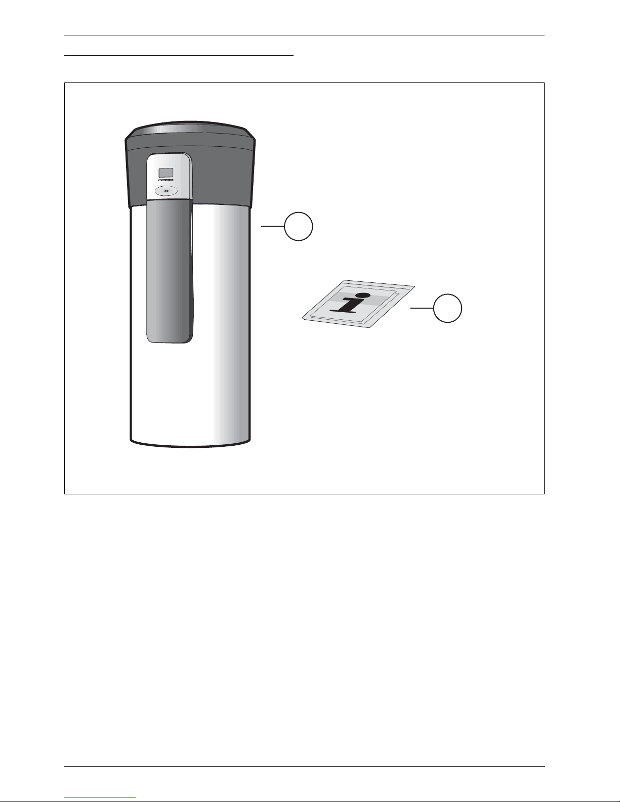
2 Standard delivery . . . . . . . . . . . . . . . . . . . . . . . . . . . . . . . . . . . . . 4
3 Information about the appliance . . . . . . . . . . . . . . . . . . . . . . . . . 5
3.1 Intended use . . . . . . . . . . . . . . . . . . . . . . . . . . . . . . . . . . 5
3.2 Overview of boiler types . . . . . . . . . . . . . . . . . . . . . . . . . 5
3.3 Type plate . . . . . . . . . . . . . . . . . . . . . . . . . . . . . . . . . . . . . 5
3.4 Description of appliance . . . . . . . . . . . . . . . . . . . . . . . . . 5
3.5 Accessories (not included in standard delivery) . . . . . . 5
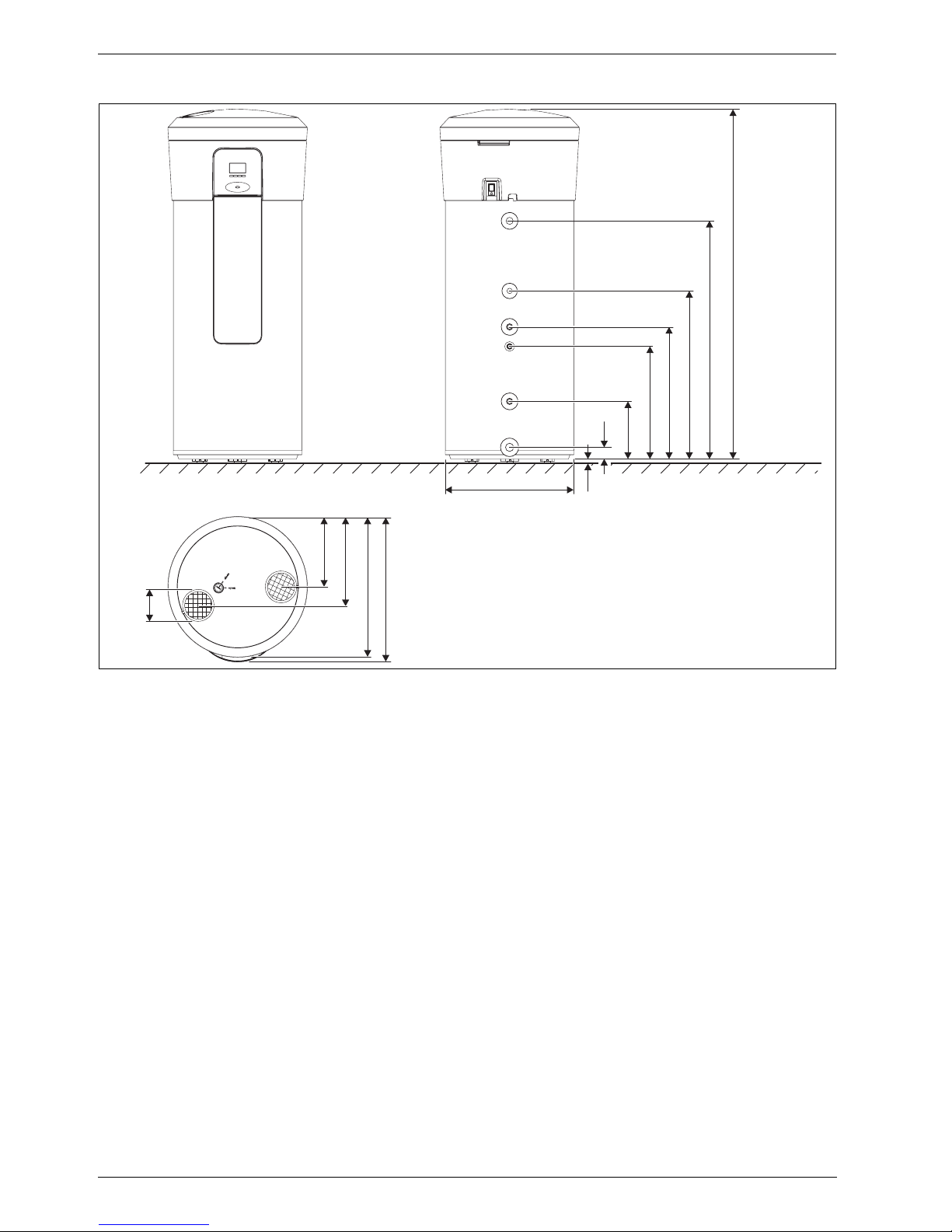
3.6 Dimensions and minimum clearances . . . . . . . . . . . . . . 6
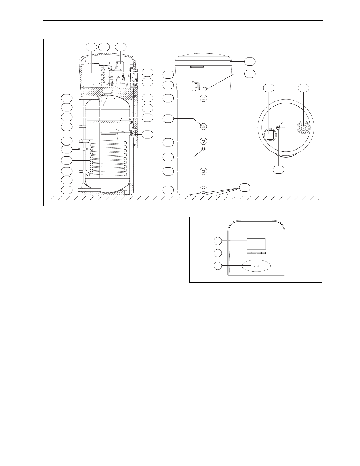
3.7 Appliance layout . . . . . . . . . . . . . . . . . . . . . . . . . . . . . . . 7
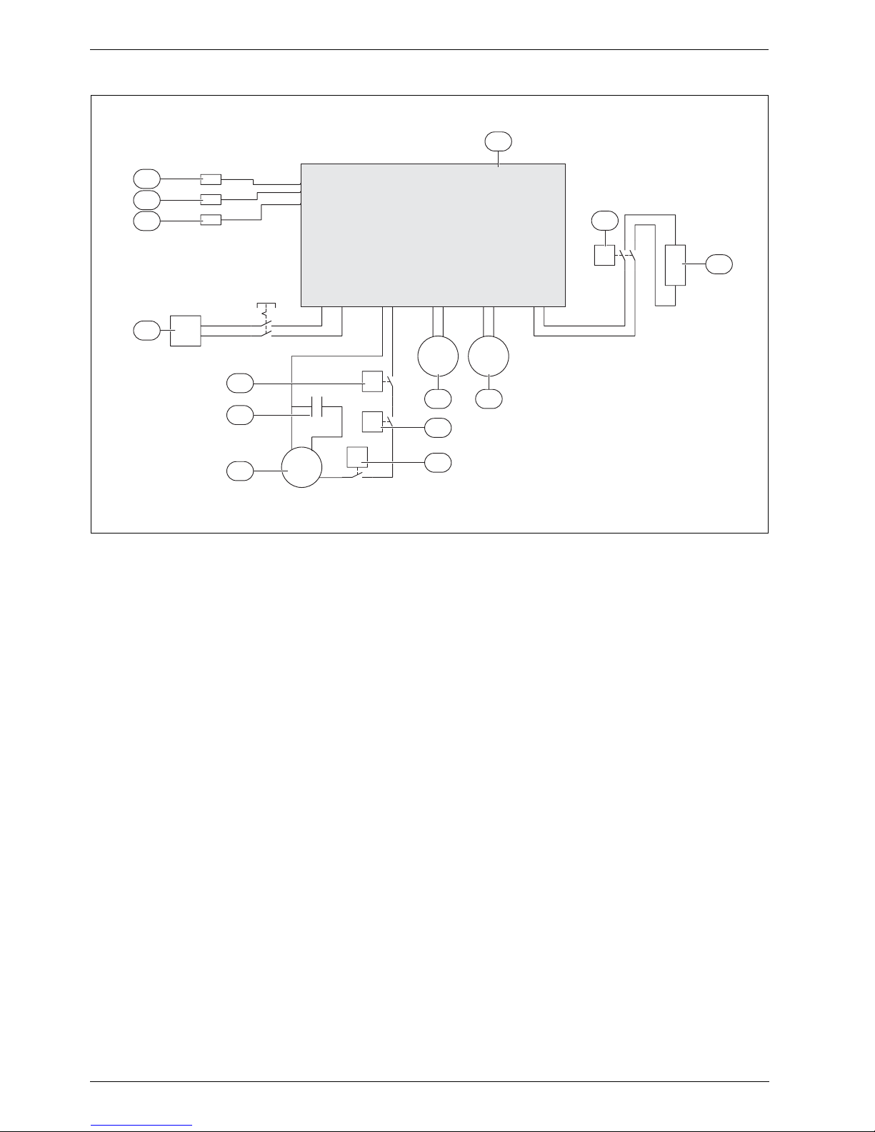
3.8 Electrical wiring diagram . . . . . . . . . . . . . . . . . . . . . . . . . 8
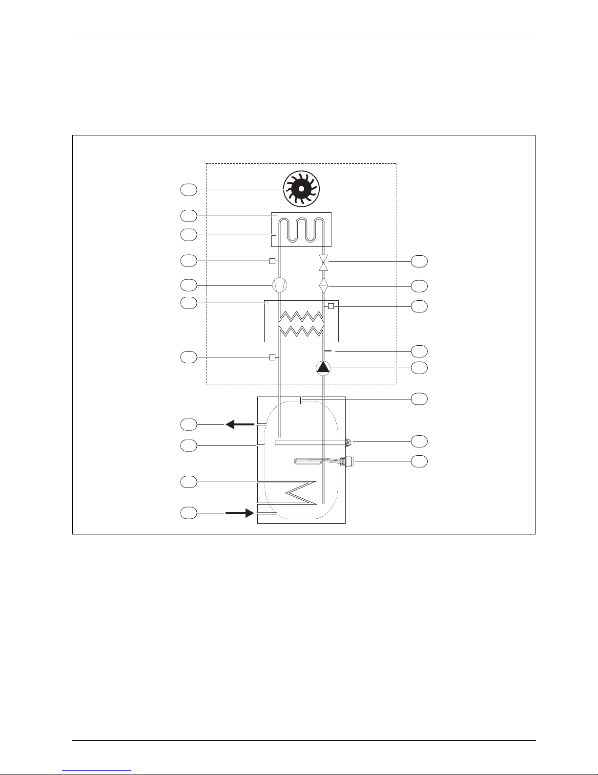
3.9 Refrigerant circuit . . . . . . . . . . . . . . . . . . . . . . . . . . . . . . 9
3.10 Safety, control and protective devices . . . . . . . . . . . . 10
3.10.1 High-pressure/low-pressure pressure switch . . . . . . 10
3.10.2 High limit safety cut-out . . . . . . . . . . . . . . . . . . . . . . . . 10
3.10.3 Temperature sensor for air inlet . . . . . . . . . . . . . . . . . 10
3.11 Corrosion protection . . . . . . . . . . . . . . . . . . . . . . . . . . 10
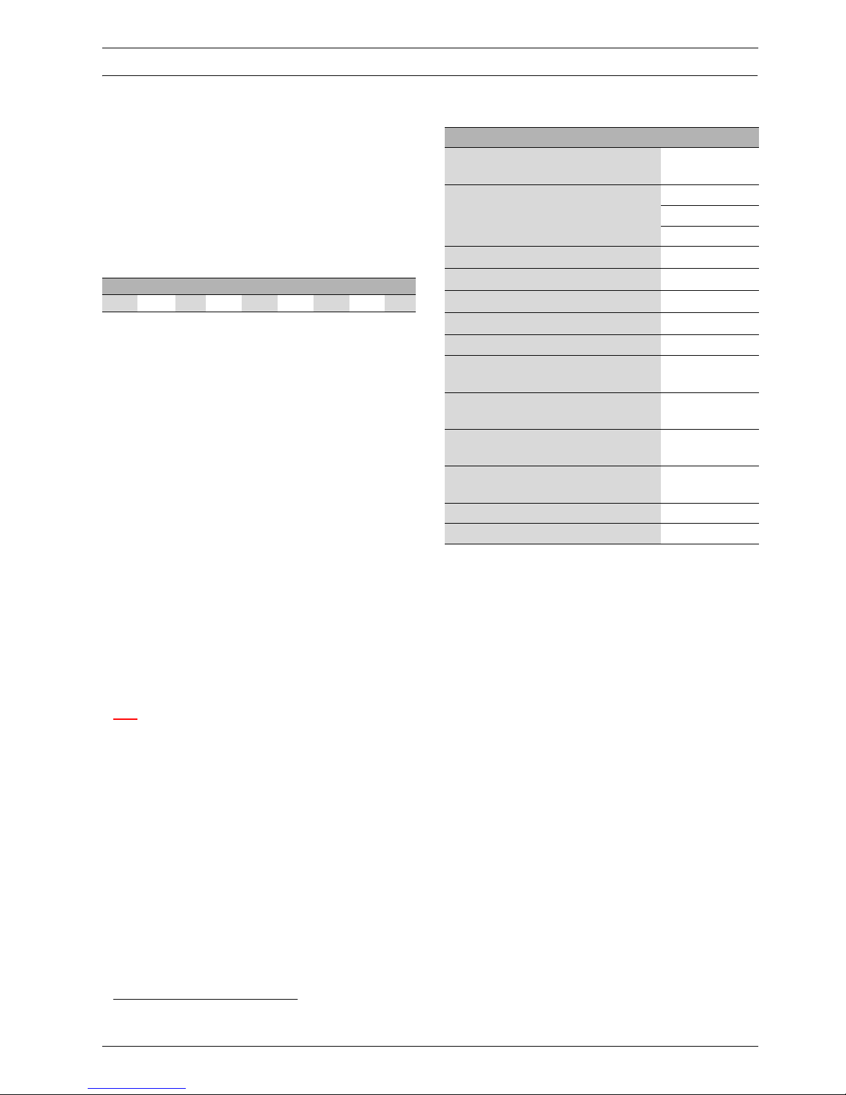
3.12 Specification . . . . . . . . . . . . . . . . . . . . . . . . . . . . . . . . 11
3.13 System scheme . . . . . . . . . . . . . . . . . . . . . . . . . . . . . . 12
3.13.1 Heat pump for DHW heating with boiler support . . . . 12
3.13.2 Heat pump for DHW heating with solar thermal
system support . . . . . . . . . . . . . . . . . . . . . . . . . . . . . . . 13
4 Transport and storage . . . . . . . . . . . . . . . . . . . . . . . . . . . . . . . 13
5 Installation . . . . . . . . . . . . . . . . . . . . . . . . . . . . . . . . . . . . . . . . . 14
5.1 Installation location . . . . . . . . . . . . . . . . . . . . . . . . . . . 14
5.2 Secure the appliance . . . . . . . . . . . . . . . . . . . . . . . . . . 14
5.3 Installing the air ducts . . . . . . . . . . . . . . . . . . . . . . . . . 15
5.3.1 Open flue operation . . . . . . . . . . . . . . . . . . . . . . . . . . . 15
5.3.2 Functioning with outside air . . . . . . . . . . . . . . . . . . . . 15
5.4 Installation . . . . . . . . . . . . . . . . . . . . . . . . . . . . . . . . . . 15
5.5 Connection for the internal indirect coil . . . . . . . . . . . 16
5.6 DHW circulation . . . . . . . . . . . . . . . . . . . . . . . . . . . . . . 16
5.7 Condensate hose connection . . . . . . . . . . . . . . . . . . . 16
5.8 Expansion vessel (accessories not included in
standard delivery) . . . . . . . . . . . . . . . . . . . . . . . . . . . . . 16
5.9 Filling the storage tank . . . . . . . . . . . . . . . . . . . . . . . . 16
5.9.1 Water characterisitcs . . . . . . . . . . . . . . . . . . . . . . . . . . 17
6 Electrical Connections . . . . . . . . . . . . . . . . . . . . . . . . . . . . . . . 17
6.1 Appliance's electrical connection . . . . . . . . . . . . . . . . 18
7 Commissioning . . . . . . . . . . . . . . . . . . . . . . . . . . . . . . . . . . . . . 18
7.1 Before commissioning . . . . . . . . . . . . . . . . . . . . . . . . . 18
7.2 Switching the appliance on/off . . . . . . . . . . . . . . . . . . 18
8 Operation . . . . . . . . . . . . . . . . . . . . . . . . . . . . . . . . . . . . . . . . . . 18
8.1 Working display . . . . . . . . . . . . . . . . . . . . . . . . . . . . . . 18
8.2 Working modes . . . . . . . . . . . . . . . . . . . . . . . . . . . . . . 18
8.3 „Operating“ menu . . . . . . . . . . . . . . . . . . . . . . . . . . . . . 19
8.3.1 „manual“ mode . . . . . . . . . . . . . . . . . . . . . . . . . . . . . . . 19
8.3.2 „P1“, „P2“ and „P3“ modes . . . . . . . . . . . . . . . . . . . . . . 19
8.3.3 „Full“ mode . . . . . . . . . . . . . . . . . . . . . . . . . . . . . . . . . . 19
8.3.4 „Off“ mode . . . . . . . . . . . . . . . . . . . . . . . . . . . . . . . . . . . 19
8.4 Setting the DHW temperature . . . . . . . . . . . . . . . . . . . 19
8.5 „Main“ menu . . . . . . . . . . . . . . . . . . . . . . . . . . . . . . . . . . 20
8.5.1 „Mode“ function - heating modes . . . . . . . . . . . . . . . . . 20
8.5.2 „Prog“ function - Timetable operation programming . 21
8.5.3 „Leg“ function - automatic thermal disinfection . . . . . 22
8.5.4 „Set“ function - adjustments . . . . . . . . . . . . . . . . . . . . . 23
8.5.5 „Purg“ function - purge . . . . . . . . . . . . . . . . . . . . . . . . . 23
8.5.6 „Info“ function - information . . . . . . . . . . . . . . . . . . . . . 23
8.6 Troubleshooting . . . . . . . . . . . . . . . . . . . . . . . . . . . . . . 23
8.7 Factory configurations . . . . . . . . . . . . . . . . . . . . . . . . . 24
8.8 Selecting the temperature units - „°C“ or „°F“ . . . . . . . 24
8.9 Setting the time and day of the week . . . . . . . . . . . . . . 24
8.10 Controls . . . . . . . . . . . . . . . . . . . . . . . . . . . . . . . . . . . . . 25
9 Environment / disposal . . . . . . . . . . . . . . . . . . . . . . . . . . . . . . . 25
10 Maintenance . . . . . . . . . . . . . . . . . . . . . . . . . . . . . . . . . . . . . . . . 26
10.1 General inspections . . . . . . . . . . . . . . . . . . . . . . . . . . . . 26
10.2 Performance check . . . . . . . . . . . . . . . . . . . . . . . . . . . . 26
10.3 Checking/replacing the magnesium anode . . . . . . . . . 26
10.4 Cleaning . . . . . . . . . . . . . . . . . . . . . . . . . . . . . . . . . . . . . 26
10.5 Condensate hose . . . . . . . . . . . . . . . . . . . . . . . . . . . . . . 26
10.6 Safety valve . . . . . . . . . . . . . . . . . . . . . . . . . . . . . . . . . . 26
10.7 Refrigerant circuit . . . . . . . . . . . . . . . . . . . . . . . . . . . . . 27
10.8 High limit safety cut-out . . . . . . . . . . . . . . . . . . . . . . . . 27
10.9 Draining the storage tank . . . . . . . . . . . . . . . . . . . . . . . 27
11 Display . . . . . . . . . . . . . . . . . . . . . . . . . . . . . . . . . . . . . . . . . . . . . 28
11.1 Faults that are shown on the display . . . . . . . . . . . . . . 28
11.2 Displays . . . . . . . . . . . . . . . . . . . . . . . . . . . . . . . . . . . . . 28

Key to symbols and safety instructions
SUPRAECO W – 6 720 646 161 (2012/04) 3
1 Key to symbols and safety instructions
1.1 Key to symbols
Warnings
Keywords indicate the seriousness of the hazard in terms of the
consequences of not following the safety instructions.
•NOTICE indicates that material damage may occur.
•CAUTION indicates that minor to medium injury may occur.
•WARNING indicates that serious injury may occur.
•DANGER indicates possible risk to life.
Important information
Additional symbols
1.2 Safety instructions
Installation
BInstallation must only be carried out by an authorised contractor.
BDo not install the appliance in the following locations:
–outside
–in locations prone to corrosion
–in locations with a temperature below +5 °C
–in potentially explosive locations.
BCheck the tightness of all hydraulic connections before connecting
the appliance to the power supply.
BWait until the appliance is at the installation location to remove it from
its original packaging.
Danger of scalding
BPossible to operate with temperatures higher than 60 °C. Please
install a thermostatic mixing valve on domestic hot water outlet
connection.
Maintenance
BThe operator is responsible for the safety and environmental
compatibility of the appliance as well as its maintenance.
BOnly authorised contractors are permitted to maintain this appliance.
BIsolate the appliance from the power supply before performing any
maintenance work.
Maintenance and repairs
BRepairs may only be carried out by an authorised heating contractor.
Faulty repairs may pose a danger to the operator and cause
malfunctions in the appliance.
BOnly original spare parts must be used.
BHave an authorised contractor perform an annual inspection and
maintain the appliance as needed.
Room/inlet air
Keep the inlet air free of contaminants. It must not contain any of the
following substances:
•corrosive substances(ammonia,sulphur,halogenproducts,chlorine,
solvents)
•fatty or explosive substances
•aerosol concentrations
Do not connect any other exhaust system to the appliance ventilation
system.
Refrigerant
BPlease observe the relevant environmental regulations when using
and reusing refrigerant. Do not allowrefrigerant to be discharged into
the environment. Use the refrigerant R134a. It is non-flammable and
does not have a destructive impact on the ozone layer.
BBefore working on parts of the refrigerant circuit, remove the
refrigerant to ensure work safety.
Use HFC-134a and PAG-ÖL for maintenance purposes. It contains
fluorinated greenhouse gas and is rated with a greenhouse potential of
1300 in the Kyoto Protocol.
Instructions to the customer
BExplain to the customer how the appliance works and how to operate
it.
BAdvise the customer that he/she must not make any modifications to
the appliance or carry out any repairs on it.
Damage due to operator error
Operator errors can lead to injuries and/or material losses.
BEnsure that children never operate this appliance unsupervised or
play with it.
BEnsure that only individuals who can operate this appliance correctly
have access to it.
Warnings in this document are framed and identified by
a warning triangle which is printed on a grey
background.
Electrical hazards are identified by a lightning symbol
surrounded by a warning triangle.
Important information in cases where there is no risk of
personal injury or material losses is identified by the
symbol shown on the left. It is bordered by horizontal
lines above and below the text.
Symbol Meaning
Ba step in an action sequence
Æa reference to arelated part in the document or to other
related documents
•a list entry
–a list entry (second level)
Table 1

Standard delivery
SUPRAECO W – 6 720 646 161 (2012/04)
4
2Standarddelivery
Fig. 1
[1] Heat pump
[2] Set of printed documents for the appliance
1
2
6720645393-03.3V

Information about the appliance
SUPRAECO W – 6 720 646 161 (2012/04) 5
3 Information about the appliance
Appliances of the HP270 series are heat pumps which use the energy in
the ambient air for domestic hot water (DHW) heating.
3.1 Intended use
The appliance may only be used for DHW heating.
Using the appliance for any other purpose will be considered incorrect
use. Junkers accepts no liability for any damage resulting from such use.
Theapplianceis notsuitableforindustrialapplications.Itis approvedfor
household use only.
3.2 Overview of boiler types
[HP] Heat pump
[270] Storage tank capacity
[-1] Version
[E] Electronic control unit
[1] Number of internal indirect coils in the storage tank
[F] Floor installation
[I] Indoor air intake
[V] Vertical installation
[S] Side connections
3.3 Type plate
The type plate is located on the rear side of the appliance.
There you will find detailson theappliance performance, part numbers,
approval data, the coded data of manufacture (FD) and other
specifications.
3.4 Description of appliance
Appliance for DHW heating with the following features:
•Glass-lined steel storage tank with thermal insulation using rigid
polyurethane foam.
•DHW storage tank corrosion-protected using internal magnesium
anode.
•Separate refrigerant and DHW circuits.
•Heat pump automatically stops in the operating mode "Heat pump"1)
if the air inlet temperature is below
+5 °C or above 35 °C
•High-pressure/low-pressure pressure switch to protect the
refrigerant circuit.
•R134a used as the refrigerant.
•DHW temperatures between 30 °C and 70 °C (the factory setting for
the DHW temperature is 50 °C).
3.5 Accessories (not included in standard delivery)
HP 270 -1 E 1FIVS
Table 2
1) ÆSection 8.5.1
Description Part number
Fixation Brackets to fix ventilation pipes 7 746 901 002
Expansion vessel 12l
Expansion vessel 18l
Expansion vessel 25l
7 747 204 675
7 747 204 676
7 747 204 677
"T" for inlet air source selection 7 746 900 714
Shut-off valve / check valve ¾ “ 7 709 500 048
Shut-off valve / check valve 1“ 7 709 500 080
Weather louvre 7 719 003 334
Roof outlet 7 719 003 366
Flexible insulated (thermal and acoustic) ducts -
10m
7 719 003 329
Air inlet and air outlet ducts 500 mm 7 746 900 698
Air inlet and air outlet ducts 1000 mm 7 746 900 702
Air inlet and air outlet ducts 2000 mm 7 746 900 706
45° bend 7 746 900 690
90° bend 7 746 900 694
Table 3

Information about the appliance
SUPRAECO W – 6 720 646 161 (2012/04)
6
3.6 Dimensions and minimum clearances
Fig. 2 Appliance dimensions
6720645393-05.2V
666.5
25
60
296
580
680
1225
865
1800
362
724
745
390
160

Information about the appliance
SUPRAECO W – 6 720 646 161 (2012/04) 7
3.7 Appliance layout
Fig. 3 Heat pump
[1] Cold water inlet - G1¼ “
[2] Internal indirect coil outlet - G1“
[3] Internal indirect coil inlet - G1"
[4] Sensor well for temperature sensor (data for programming unit
for the solar thermal system or central heating)
[5] DHW circulation inlet - G3/4"
[6] DHW outlet G1"
[7] Internal indirect coil
[8] Thermal insulation
[9] Cold water inlet to condenser
[10] Cold water outlet from condenser
[11] Air fan
[12] Evaporator
[13] Condenser (gas/water heat exchanger)
[14] Compressor
[15] Sensor well for DHW temperature sensor
[16] Magnesium anode
[17] Electric heating insert
[18] ON/OFF switch
[19] Adjustable feet (3x)
[20] Air outlet aperture
[21] Air inlet aperture
[22] Condensate outlet
[23] DHW circulation pump
[24] Front casing
[25] Housing ring
[26] Housing lid
[27] Fastening for housing lid
Fig. 4 User interface
[1] Display
[2] Setting buttons
[3] Function/fault display for appliance
27
1
2
4
3
6
11 12 13
19
6720645393-06.1V
25
26
16
17
5
9
10
3
8
7
2
1
5
24
4
18
22
15
23
14
20 21
6
6720645393-01.1V
2
1
3
menu -ok
+

Information about the appliance
SUPRAECO W – 6 720 646 161 (2012/04)
8
3.8 Electrical wiring diagram
Fig. 5
[1] Temperature sensor for air inlet
[2] Storage tank temperature sensor for DHW
[3] Storage tank temperature sensor for cold water
[4] Power cable
[5] High-pressure pressure switch
[6] Capacitor for compressor
[7] Compressor
[8] Temperature controller for compressor
[9] Low-pressure pressure switch
[10] DHW circulation pump
[11] Air fan
[12] Resistor
[13] Resistor for high-limit safety cut-out
[14] Control unit
1
2
3
4
7
9
5
10 11
8
12
13
14
MM
M
6720646160-20.1V
6

Information about the appliance
SUPRAECO W – 6 720 646 161 (2012/04) 9
3.9 Refrigerant circuit
The refrigerant circuit is a closed system in which the refrigerant R134a
circulates as a heat transfer medium.
The evaporator transfers the heat from the air to the refrigerant circuit,
and the refrigerant evaporates into a gas.
The compressor compresses the refrigerant R134a, thus increasing its
temperature.
Then the heat is transferred via a heat exchanger, also referred to as a
condenser, to the storage tank water. The refrigerant R134a condenses
in the process.
R134a flows through the expansion valve in liquid state with decreasing
pressure. Then it is routed back to the evaporator.
Fig. 6
[1] Air fan
[2] Evaporator
[3] Compressor
[4] Condenser (gas/water heat exchanger)
[5] NTC temperature sensor (air inlet)
[6] DHW connection
[7] Temperature sensor aperture (data for programming unit for
solar thermal system or central heating)
[8] Internal indirect coil
[9] Cold water inlet
[10] Electric heating insert
[11] NTC temperature sensor (top of storage tank)
[12] DHW circulation pump
[13] NTC temperature sensor (bottom of storage tank)
[14] Dry filter
[15] Expansion valve
[16] Low-pressure pressure switch
[17] Water purge
[18] High-pressure pressure switch
[19] Magnesium anode
1
2
3
4
6
7
8
9
11
12
13
14
15
6720646160-23.3V
10
5
16
17
18
19

Information about the appliance
SUPRAECO W – 6 720 646 161 (2012/04)
10
3.10 Safety, control and protective devices
3.10.1 High-pressure/low-pressure pressure switch
The pressure switch protects the refrigerant circuit from overpressure.
The pressure switch switches off the appliance in the event of
overpressure. An automatic reset occurs as soon as the pressure in the
refrigerant circuit has been regulated.
3.10.2 High limit safety cut-out
The high-pressure safety cut-out ensures that the storage tank's water
temperature does not exceed the prescribed limit. If the temperature
rises above the limit, the heating process is interrupted. The reset is
performed manually by an authorised contractor.
3.10.3 Temperature sensor for air inlet
The temperature sensor measures the temperature of the inlet air in the
evaporator. If the measured value is outside operating temperature
range, DHW productionautomatically switches from "Combi" operating
mode to "Electrical" operating mode. If the appliance is in "Heat"
operating mode, production is stopped until the measured value is
within operating temperature range.
3.11 Corrosion protection
The internal wall of the DHW storage tank is glass lined (double coating).
As an additional corrosion protection measure, the storage tank is
equipped with an internal magnesium anode. It must be inspected at
regular intervals and replaced if necessary.
In regions with more corrosive water, special safety measures (filter,
etc.) must be taken, and the magnesium anode must be serviced at
shorter time intervals.
First maintenance must be performed 6 months after
installation.

Information about the appliance
SUPRAECO W – 6 720 646 161 (2012/04) 11
3.12 Specification
Unit HP270...O...
Operation
Heating output (without electric heating insert)1)
1) As per EN255-3, 20 °C air, DHW heating from 15 °C to 45 °C
kW 2.0
Performance coefficient (COP)1) – 3.5
Heating output of integrated electric heating insert kW 2.0
Air inlet
Air flow rate (without/with piping) m3/h 350/330
Operating temperature °C +5 ... +35
Compressor
Refrigerant R134a g375
Maximum pressure bar 27
Domestic Hot Water
Storage tank capacity l 270
Maximum heating output without/with electric heating insert kW 2.0/4.0
Area of heat exchanger (internal indirect coil) m21.5
Maximum water temperature without/with electric heating insert °C 60/70
Maximum DHW flow rate1) l/day 1270
Maximum operating pressure bar/MPa 10/1
Cooling constant in 24 hours, as per DIN 4753 Part 82)
2) 20 °C air, DHW temperature 55 °C
kWh/day 0.96
Data on the electrical connecting leads
Power supply voltage V 230 (+10%/-15%)
Frequency Hz 50
Electric current (without/with electric heating insert) A 2.6/11.3
Total power consumption kW 2.6
Power consumption (without electric heating insert) kW 0.6
Protection class I
IP rating (without/with piping) IP 21/24
General data
Sound pressure level (at a distance of 1 m) dB(A) 45
Dimensions, W x H x D mm 724 × 1825 × 745
Net weight (without packaging) kg 143
Table 4

Information about the appliance
SUPRAECO W – 6 720 646 161 (2012/04)
12
3.13 System scheme
3.13.1 Heat pump for DHW heating with boiler support
Fig. 7
[1] Additional heating element (f.i. gas boiler)
[2] DHW circulation pump
[3] Cold water inlet
[4] Shut-off valve
[5] Check valve
[6] Safety valve
[7] Expansion vessel
[8] Drain set
[9] Heat pump
[10] DHW connection
[11] Outlet siphon
[12] Mixing valve
[13] Integrated electric heating element
1
2
3 4 5 11
9
67
10
6720646160-24.2V
8
3
12
13

Transport and storage
SUPRAECO W – 6 720 646 161 (2012/04) 13
3.13.2 Heat pump for DHW heating with solar thermal system support
Fig. 8
[1] Thermal solar collectors
[2] Solar programming unit
[3] Cold water inlet
[4] Shut-off valve
[5] Check valve
[6] Safety valve
[7] Expansion vessel
[8] Drain set
[9] Heat pump
[10] DHW connection
[11] Outlet siphon
[12] Solar pump station
[13] Container for safety valve drain
[14] Mixing valve
[15] Integrated electric heating element
4 Transport and storage
General
The appliance is delivered on a single pallet and is protected against
transport damage by special packaging.
Always store and transport the appliance in its original packaging, in
vertical position (check "tilt label" prior to installation) and with the
storage tank empty. Ambient temperatures of -20 °C to +60 °C are
permissible for storage and transport.
10
6720646160-28.2V
3 4 5 11
678
1
212
13
7
9
3
14
15
NOTICE: Transport damage!
BAvoid tilting the appliance at an angle of more than
45°.
BTake care when handling the appliance.
BTo avoid dropping the appliance and damaging
internal components, do not pivot the appliance.
NOTICE: Transport damage!
BTo avoid transport damage, wait until the appliance is
at the installation location to remove the protective
packaging.
BTransport and set down the appliancecarefully.Jerky
movements can damage the internal glass-lined
coating, the components and their connections or the
external casing.
BUse straps to prevent the appliance from becoming
scratched.
BUsesuitablemeansoftransporttobringtheappliance
to the installation location (special car, pallet truck,
etc).

Installation
SUPRAECO W – 6 720 646 161 (2012/04)
14
Fig. 9
Manual transport
To bring the appliance into position at the installation location, place
straps around the storage tank.
5Installation
BInstallation must only be carried out by an authorised contractor.
BThe heat pump installation must follow the applicable regulations.
BCheck that all pipe connections are intact and have not shaken loose
during transportation.
BCheck the colour of the "tilt label" on the rear side of the appliance's
packaging. If the label is blue, the appliance cannot be installed and
should be returned on it‘s original packaging.
5.1 Installation location
Please note the following when choosing the installation location:
•The appliance must be installed in a dry, frost-free room. Optimum
appliance performance is achieved at room temperatures between
+5 °C and +35 °C.
•Check that the appliance‘s installation area has the required
resistance and alignment.
•The air outlet and air inlet must not bein locations where there is a risk
of explosion from gas, steam or dust.
•If open flue gas appliances are already installed at the installation
location, the appliance may not be operated with room air circulation.
Use of an inlet pipe for fresh air or another facility ensuring that the
inlet air is separate from the gas appliance is mandatory.
•Ensure that condensate drains correctly.
•The plinth of the appliance must be strong enough (the appliance
weighs about 400 kg when the storage tank is filled, with the weight
distributed equally over its 3 adjustable feet).
To ensure faultless operation and easy access to all components and
connections for maintenance and repairs, maintain the minimum
clearances specified in Fig. 10.
Fig. 10 Recommended minimum clearances (mm)
5.2 Secure the appliance
BCheck the colour of the tilt label.
If it is not blue in the top arrow, remove the shrink wrap and external
protective packaging.
Fig. 11
BLift the appliance from its pallet.
BTo correctly align the appliance at the installation location, adjust the
height of the adjustable feet.
NOTICE: Damage from straps!
BRemove front casing (ÆFig. 3, [24]).
BMake sure that the straps do not scratch or make
indentations on the surface of the appliance.
BDo not fasten the straps at the resistor (ÆFig. 3,
[17]) or at the temperature sensor aperture (Æ
Fig. 3, [4]).
6720646160-45.1V
To ensure that the system operates faultlessly and the
condensate drains, the appliance must be aligned
vertically. The appliance must not tilt more than 1°,
preferably in the direction of the condensate drain.
NOTICE: Damage in the external casing!
BDo not tilt the appliance more than 20°.
500
400
2200
430
6720645393-04.2V
TransportControlInt´lGmbh
AmKnick9,22113Oststeinbek
Tel:0049407138
402
Fax:0049407132
494
BLUEBEDSIN
ARROWINDICATES
COUNTAINERWAS
TIPPEDOR
MISHANDLED
MADEINU.S.A.
PATENTNO.3,926,144
TELL
N
TIP
TransportControlInt´lGmbh
AmKnick9,22113Oststeinbek
Tel:0049407138402
Fax:0049407132494
BLUEBEDSIN
ARROWINDICATES
COUNTAINERWAS
TIPPEDOR
MISHANDLED
MADEINU.S.A.
PATENTNO.3,926,144
TELL
N
TIP
Transport Control Int´l Gmbh
Am Knick 9,22113 Oststeinbek
Tel: 0049 40 713 84 02
Fax: 0049 40 713 24 94
BLUE BEDS IN
ARROW INDICATES
COUNTAINER WAS
TIPPED OR
MISHANDLED
MADE IN U.S.A.
PATENTNO.3,926,144
TELL
N
TIP
Transport Control Int´l Gmbh
Am Knick 9,22113 Oststeinbek
Tel: 0049 40 713 84 02
Fax: 0049 40 713 24 94
BLUE BEDS IN
ARROW INDICATES
COUNTAINER WAS
TIPPED OR
MISHANDLED
MADE IN U.S.A.
PATENTNO.3,926,144
TELL
N
TIP
6720646160-46.1V

Installation
SUPRAECO W – 6 720 646 161 (2012/04) 15
5.3 Installing the air ducts
Inlet air can be taken from the room where the appliance is installed,
from another room or from the outside. In the last two cases, ducts must
be assembled in the air inlet.
Choose a room for the air inlet. Observe the average air temperature and
maximum required air flow rate (ÆTab. 4). To achieve as little air
resistance as possible, install the air inlet and air outlet ducts (Ø 160
mm) as straight as possible. The length of the ducts for the air inlet and
air outlet must not exceed 6 m. Do not install more than two 90° bends.
For each additional bend, reduce the duct length by 1 m.
To ensure that condensate forming in the air inlet and air outlet ducts
drains from the appliance:
BInstall air ducts at a slight angle to the opposite side ofthe air inlet and
air outlet apertures on the top side of the appliance.
BLimit the pressure drop in the linesto 10 Pa to ensure a minimum inlet
air flow rate of 330 m3/h as well as the stated heating output.
5.3.1 Open flue operation
If the heat pump can be operated using the air in the installation room,
ensure that the room has a volume greater than 20 m3.
Fig. 12
[1] Air inlet
[2] Air outlet
Fig. 13 Corresponding duct length (L)
5.3.2 Functioning with outside air
When using outside air, assure that the ducts are protected with the
correct accessories.
5.4 Installation
BDetermine the nominal diameter of the room's water installation.
Please note the current water pressure and the expected pressure
drop.
BCarry out the water installation in accordance with the applicable
regulations. Please observe the local regulations on DHW
installations.
BThe water pipes can be rigid or flexible. To avoid corrosion, take into
account the behaviour of the materials used in the pipework and the
connections.
To ensure maximum appliance performance and avoid
condensation in the outer ducts surface, use thermally
and acoustically insulated ducts.
Ø 160 mm
Duct length for the air inlet and air outlet 6 m
Reduction for each 90° bend 1 m
Table 5
6720645393-07.2V
1
2
NOTICE: Damage to the ducts due to improper
handling!
BDo not allow ducts to become contaminated during
installation.
BIf necessary, flush the ducts with water prior to
commissioning.
It is advisable to purge the installation beforehand, the
presence of dirt may reduce the flow and, in extreme
cases, cause a blockage.
It is recommended that a water filter be installed at the
the appliance's cold water inlet.
NOTICE: Corrosion damage to the storage tank's
connections!
If the connections are copper:
BUse an isolation fitting1) for the hydraulic connection.
This extends the service life of the magnesium anode.
1) Accessory not included in standard delivery
6720645393-08.3V
L
2T
L
T1
L1
C1 C2
L2
L4
L = L1+C1+L2
T1
L = L3+C2+L4
L=L +L
Ø 160mm: L 6m
T2
T1 T2
≤
L3

Installation
SUPRAECO W – 6 720 646 161 (2012/04)
16
To avoid heat loss and improve appliance efficiency:
BInsulate all water connections.
Safety valve1)
BInstall a safety valve at the appliance's cold water inlet.
5.5 Connection for the internal indirect coil
The appliance is equipped with an internal indirect coil for backup
heating from solar thermal or central heating systems.
If DHW temperature in the tank reaches 80 °C, the external controller
must switch off the backup circuit. This is to prevent damage to the heat
pump's refrigerant circuit or failure of the safety temperature limiter.
If the internal indirect coil is not used:
BDo not remove the plugs from the internal indirect coil's inlet and
outlet apertures.
DHW temperature sensor in the storage tank
BInstall DHW temperature sensor in the correct pipe (ÆFig. 3, [4]).
BInsulate the pipe to prevent heat loss.
5.6 DHW circulation
With regard to the output, DHW circulation should only be used when it
is really needed. To avoid heat loss through a circulation system
connected to the DHW distributor system, this system must be
controlled using a valve or a similar device.
5.7 Condensate hose connection
The condensate is drained on the rear side of the appliance.
BConnectthecondensatehose1) tothecondensatedrain(Fig. 14,[1])
to allow the condensate to drain freely.
BDrain condensate via an outlet siphon (Fig. 14, [2]).
Fig. 14 Condensate drain
[1] Condensate drain
[2] Outlet siphon
5.8 Expansion vessel (accessories not included in
standard delivery)1)
BInstall the expansion vessel at the cold water connection between the
storage tank and the safety assembly.
Table 6 serves as a reference for the selection of the expansion vessel.
The capacity of the expansion vessel must be selected subject to the
waterpressureinthe system.Detailsrefertoastorage tanktemperature
of 60 °C.
5.9 Filling the storage tank
1) Accessory not included in standard delivery
If the water inlet pressure is higher than 8 bar - 80% the
allowable maximum value (10 bar) -, install a check
valve. The safety valve is controlled as soon as the water
pressure in the appliance is more than 10 bar. In this
case it must be possible to divert the drain to a container.
NEVER SEAL OFF THE SAFETY VALVE'S DRAIN. Do not
install any accessories between the safety valve and the
appliance's cold water inlet.
NOTICE:
The safety valve drain tube must be installed in a frost
free environment and downwards oriented.
WARNING: Danger of scalding!
Hot water can cause serious scalding.
BWarn occupants of risk of scalding.
BInstall a thermostatic mixing valve to limit the hot
water outlet temperature.
Heat recovering time will be higher when using a
recirculating system.
To prevent water loss from the safety valve, a DHW
expansion vessel can be installed.
Storage
tank type
Safety valve
(max.
pressure)
Water
pressure in
the system
Capacity of the
expansion vessel
corresponding to the
switch-on pressure of
the safety valve
HP 270...
6 bar
2 12 l
318 l
425 l
8 bar
2 12 l
312 l
418 l
10 bar
2 12 l
312 l
418 l
Table 6
NOTICE: Damage to the appliance!
BPrior to commissioning the appliance, fill the storage
tank with water and ventilate it.
6720646160-26.1V
1
2

Electrical Connections
SUPRAECO W – 6 720 646 161 (2012/04) 17
BOpen DHW connection (Fig. 6, [6]) and one or more hot water taps.
BOpen storage tank cold water inlet (Fig. 6, [9]).
Storage tank filling starts.
BClose hot water taps only when water flow is free of air pockets.
BConnect the appliance to the power supply via a connection socket
with an earth conductor.
BMove main switch (on the rear side of the appliance above the power
cable (ÆFig. 3, [18])) to "I".
BRotate circulation pump speed selector to position „III“.
Fig. 15 Circulation pump
BActivate „Purg“ function (Æpage 28, section 8.5.6).
BOpen purge valve (ÆFig. 16, [1]) until water drops out through the
purge valve outlet.
Ensure that water drains correctly.
Fig. 16 Purge valve
[1] Purge valve
[2] Condenser (gas/water heat exchanger)
BClose purge valve.
BWait for about 5 minutes until „Purg“ mode goes off.
BRotate circulation pump speed selector to position „I“.
Filling procedure is concluded.
If, after a few minutes of operation, display shows „E09“,
you should:
BReset the appliance (Æpage 23, paragraph „Resetting the system“).
BRotate circulation pump speed selector to position „III“.
BActivate „Purg“ function (Æpage 28, section 8.5.6).
BReopen purge valve for a few seconds to assure the complete purge of
the system..
BRotate circulation pump speed selector to position „I“.
5.9.1 Water characterisitcs
Usage of water with unsuitable characterisitcs can result in prematurely
failing.
6 Electrical Connections
All control, monitoring and safety equipment of this appliance is fully
wired and tested.
Check if the purge valve outlet is downwards oriented. If
not:
BRotate the purge valve clockwise (tightening) to
assure that the outlet is downwards oriented.
CAUTION: Risk of scalding!
BEnsure that draining water from the purge valve
presents no risk to people or property.
6720646160-51.1V
1 2
Water hardness (°dH) Water treatment
3,0 - 11,2 Not required
Table 7 Water hardness
pH Water treatment
6,5 - 9,5 Not required
< 6,5 or > 9,5 Required
Table 8 pH value
Water conductivity for sacrificial anodes
130 μS/cm - 1500 μS/cm
Table 9 Water conductivity
Enamelled tanks must not be used with completely
desalted, distilled or de-ionised potable water.
Only an authorised contractor is permitted to install the
appliance, connect it to the mains, install the air outlet/
inlet and commission the appliance.
DANGER: Risk of electric shock!
BIsolate the appliance from the power supply using the
fuse or another protective device before carrying out
any work on electrical parts.
DANGER: Risk of electric shock!The capacitor must
discharge after the appliance has been switched off.
BWait at least 5 minutes.
DANGER: Risk of electric shock!To ensure compliance
with all safety requirements, a defective connecting
cable may only be replaced by an authorised contractor.
The appliance is set at the factory to a power supply of
230 V.

Commissioning
SUPRAECO W – 6 720 646 161 (2012/04)
18
The appliance is already equipped with a cable for the power supply.
Power is supplied via the connecting cable (2 m) and an earthed wall
socket (230 V AC/50 Hz).
6.1 Appliance's electrical connection
BConnect the appliance to the power supply via a connection socket
with an earth conductor.
7Commissioning
7.1 Before commissioning
BCheck whether the storage tank is filled with water.
BCheck all fittings for leaks.
BCheck the electrical connection.
7.2 Switching the appliance on/off
Switching ON
BMove main switch (on the rear side of the appliance above the power
cable (ÆFig. 3, [18])) to "I".
Switching off
BMove main switch to "0".
8Operation
Fig. 17 Control panel
[1] Display
[2] Selection keys
[3] Indicator light/ Device error indicator
Fig. 18 Display
[1] Display
[2] Heating in heat pump mode
[3] External heat (solar or boiler)
[4] Information
[5] Parameter adjustment entry
[6] Error indicator
[7] „Service“ menu entry
[8] Days of the week
[9] „auto/man“ functioning
[10] Indicator light
[11] „Prog“ menu entry
[12] Clock adjustment
[13] Timetable
[14] Consumption
[15] Storage tank sensor positions
[16] „anti-freeze“ function
8.1 Working display
Visible display symbol
Device functioning.
Visible display symbol
Device inactive (water temperature remains at previously selected
temperature).
8.2 Working modes
Visible display symbol „ “
Operating periods in accordance with defined programming (P1, P2 or
P3).
Visible display symbol „ “
Permanent operation (24 h/7 days) without defined programming or
„Full“ mode.
NOTICE:
Fuse protection!
BThe wiring diagram must show a separate connection
for the appliance.There must be a 30 mA RCD and
earth conductor.
For safety and maintenance purposes, ensure that the
socket is accessible after installation.
The electrical connection must meet the current
standards for electrical installations in the country of
use.
NOTICE: Starting up the appliance when it has not been
filled with water will damage it beyond repair!
BOnlyoperatethe applianceonceit hasbeenfilled with
water.
After the compressor start-up, the appliance should
work, at least, for 5 minutes before it gets turned off
again.
NOTICE: Appliance damaging!
Negative temperatures can lead to water freezing.
BDo not disconnect power supply.
BMove main switch to „I“.
BSwitchtheapplianceto„Off“mode (Æsection 8.3.4,
page 19).
-or-
BDrain the appliance.
6720645393-01.1V
2
1
3
menu -ok
+
2 3 456
8
9
12
11
16
14
13
6720645393-10.1V
1 7
15 10

Operation
SUPRAECO W – 6 720 646 161 (2012/04) 19
8.3 „Operating“ menu
Access the „Operating“ menu
BPress the „menu“ key for no longer than 3 seconds.
Fig. 19 Accessing the „Operating“ menu
Accessing the „Operating“ menu provides access to the following modes
of operation:
•manual
•P1
•P2
•P3
•Full
•Off
BUse the „+“ or „-“ keys to select the desired working mode.
BConfirm using the „oK“ key
8.3.1 „manual“ mode
In this working mode, the device functions 24 hours a day, 7 days a
week, until it reaches a selected temperature. Used heat source is
defined using the Mode function (ÆChapter 8.5.1) of „Main“ menu.
Fig. 20 „manual“ mode
8.3.2 „P1“, „P2“ and „P3“ modes
„P1“ mode
Selecting this menu causes the device to function during the predefined
factory time periods (Æ„„P1“ period„, page 21).
„P2“ and „P3“ mode
Selecting this menu causes the device to function during user-defined
time periods (Æ„„P2“ and „P3“ periods, page 21).
8.3.3 „Full“ mode
In this mode, the device uses two heat sources simultaneously: the heat
pump and electrical power.
Fig. 21 „Full“ mode
This mode permits setting the water temperature anywhere between
30 °C and 70 °C.
Upon reaching the selected water temperature, the device exits „Full“
mode and returns to the mode previously selected.
8.3.4 „Off“ mode
This operating mode disconnects the device. Electrical power is only
activated for the „anti-freeze“ protection function, if necessary.
Fig. 22 Modo „Off“
„Anti-freeze“ function
The electrical power is connected when the water temperature of the
deposit reaches 5 °C. It is disconnected when the water temperature
reaches 10 °C.
8.4 Setting the DHW temperature
To go back one menu:
BPress the „menu“ key.
-or-
BDo not press any key for the following 15 seconds.
6720646160-14.1V
menu -ok
+
<3s
6720646160-37.1V
"Full" mode activation reduces device efficiency, and
should only be selected in the event of need for a rapid
increase in water temperature.
Two heat sources are used simultaneously until the
desired temperature is reached.
Only electrical heat is used over 60 °C.
The water temperature is factory-set at a value of 50 °C.
6720646160-08.1V
6720646160-10.1V

Operation
SUPRAECO W – 6 720 646 161 (2012/04)
20
BPress the „+“ or „-“ keys until the desired value is reached.
Fig. 23 Setting the temperature
BPress the „ok“ key to confirm the selection.
The selected temperature will blink 3x to signal confirmation.
8.5 „Main“ menu
Accessing the „Main“ menu
BPress the „menu“ key and hold it down for over 3 secs.
Fig. 24 Accessing the „Main“ menu
Accessing the „Main“ menu provides access to the following functions:
•Mode - „Heating modes“
•Prog - „Timetable operation programming“
•Leg - „thermal disinfection“
•Set - „adjustments“
•Purg - „purge“
•Info - „information“
BUse the „+“ or „-“ keys to select the desired menu.
BConfirm using the „ok“ key
8.5.1 „Mode“ function - heating modes
The „Mode“ function permits selection of 3 different heating modes:
•„Electrical“ mode
•„Heat pump“ mode
•„Combi“ mode
Fig. 25 „Mode“ function
„Electrical“ mode
In this mode, the only heat source used is electrical power.
Fig. 26 „Electrical“ mode
This mode permits setting the water temperature anywhere between
30 °C and 70 °C.
„Heat pump“ mode
Fig. 27 „Heat pump“ mode
This mode permits setting the water temperature anywhere between
30 °C and 60 °C.
„Combi“ mode
This mode used two heat sources, depending on conditions: the heat
pump or the electrical supply.
The selected value blinks until the selection is validated.
If the selection is not validated within 10 seconds, the
previously selected value will remain active.
6720646160-13.1V
6720646160-49.1V
menu -ok
+
>3s Water heating is only assured while air inlet is between
5 °C and 35 °C.
Very low temperatures trigger activation of the „anti
freeze“ protection function (Æpage 19).
6720646160-19.1V
6720646160-07.1V
6720646160-06.1V
Table of contents
Popular Heat Pump manuals by other brands

Carrier
Carrier 50ZH Series Guide to operating and maintaining

Samsung
Samsung RC090MHXEA Installation and maintenance manual

Daikin
Daikin ERQ125A7W1B installation manual

Carrier
Carrier Aquasnap plus 30AW Installation, operation and maintenance instructions

Panasonic
Panasonic WH-ADC0916G9E8 Service manual

Carel
Carel Heos user manual

PHNIX
PHNIX PASRW015-U Installation instructions manual

Mitsubishi Electric
Mitsubishi Electric TRANE TPKA0A 1HA70 Operation manual

G&F Manufacturing
G&F Manufacturing Gulfstream HE125RA Install & Operation Manual

State Water Heaters
State Water Heaters SHPW-25 User's information manual

Maritime Geothermal
Maritime Geothermal WH-Series Installation and service manual

Danfoss
Danfoss DHP-AQ user manual