JVC MC-BL10U User manual

MC-BL10U
LST0586-001A
MC-BL10 Blu-ray DRIVE
INSTRUCTIONS
BEDIENUNGSALEITUNG
Thank you for purchasing the JVC MC-BL10U Blu-ray DRIVE.
Before you start operating this unit, please read the instructions
carefully in order to obtain the best possible performance.
For Customer Use:
Enter below the Model No. and Serial
No. which are located at the top of the
unit. Retain this information for future
reference.
Model No. MC-BL10U
Serial No.
Blu-ray DRIVE
Blu-ray-LAUFWERK
1
A
ENGLISH
DEUTSCH

E
INSTALLATION FLOW
Follow the steps below for installation.
PRECAUTIONS BEFORE USE
INSTALLATION
Page E3, E4
●Install the MC-BL10U in the CD/DVD Library.
䡵Procedure for Opening the Door of the CD/DVD Library
䡵Procedure for Opening the Drive Storage Cover of the
CD/DVD Library
䡵Procedure for Determining the Setup Position for the MC-BL10U
䡵Procedure for Installing the MC-BL10U in the CD/DVD Library
CONNECTION
Page E4, E5
●Connect the MC-BL10U to the CD/DVD Library.
䡵Procedure for Connecting the Cables to the Back of the MC-BL10U
SETUP
Page E5
●Set the SCSI ID of the MC-BL10U and close the door of the CD/
DVD Library.
䡵Procedure for Setting the DIP Switch
䡵Procedure for Attaching the Drive Storage Cover of the CD/DVD
Library
䡵Procedure for Closing the CD/DVD Library Door
EXECUTION OF AUTOMATIC
DRIVE DETECTION MODE.
Page E6
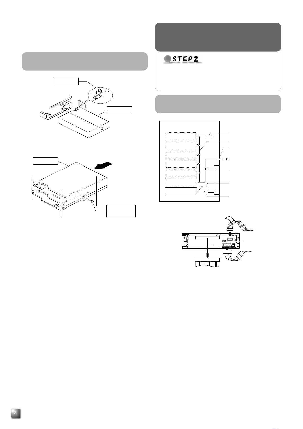
●Execute the automatic drive detection mode and connect the host
computer.
䡵Procedure for Executing the Automatic Drive Detection Mode of
the CD/DVD Library
䡵
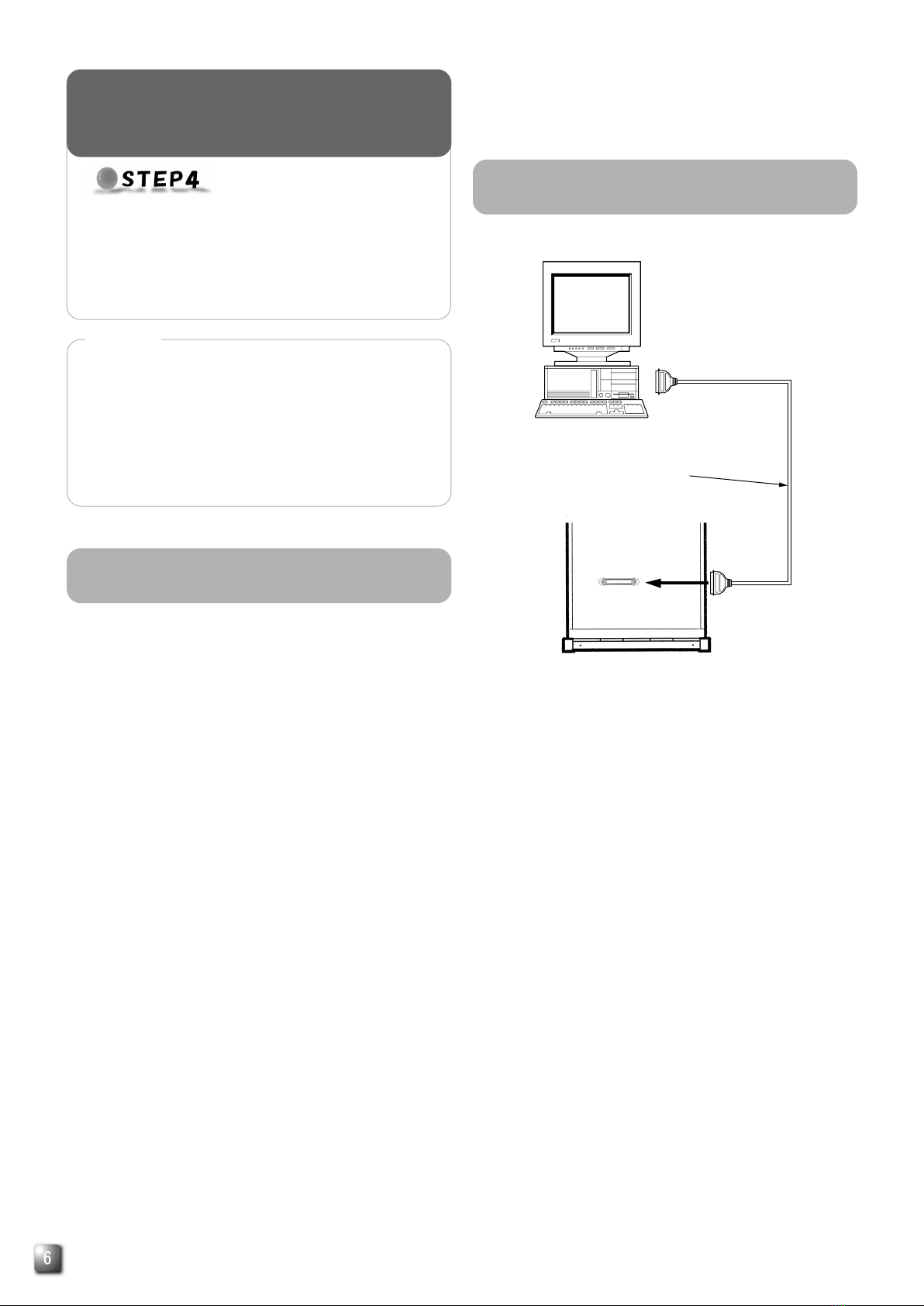
Procedure for Connecting the CD/DVD Library to the Host Com-
puter
●In case of using MC-BL10U, MC-8200LU and MC-8600LU
have following limitation of the drive units due to the power
unit capacity.
* MC-8200LU/8600LU : max 5 drive units
e.g. MC-BL10U x 5
MC-BL10U x 1 and MC-R434U x 4
MC-BL10U x 0 and MC-R434U x 6
note : MC-8100LU doesn't have this limitation.
1. DANGER: Invisible laser radiation will occur if the unit is
open due to a failed or defective interlocking device.
2. CAUTION: Do not open the top cover.There are no user
serviceable parts inside the unit; leave all servicing to
qualified service personnel.
●The MC-BL10U is a Blu-ray drive designed for use with the
JVC MC-8100LU/8200LU/8600LU “CD/DVD Library”.
●When installing this unit in a Library that is being used, please
read the instruction manual carefully.
●The MC-BL10U cannot be operated on its own.
●This unit cannot be used in combination with the following
models.
•CD-ROM Library : MC-1000 series/2000 series
•DVD-RAM Library: MC-7000 series
•CD/DVD Library : MC-8000 series
●MC-BL10U cannot be used with drives other than MC-R434U.
●For the compatible discs, see the Specifications on page E7.

E
ENGLISH
1.
Select the [DOOR OPEN MODE] on the MENU screen of
the CD/DVD Library's LCD.
2.
Press and hold the "SELECT" switch for five seconds.
3.
Turn off the power of the CD/DVD Library when [THE DOOR
CAN BE OPENED] message is displayed on the LCD.
4.
Insert the key in the key cylinder located at the center of
the door to unlock and open the door.
*The illustration shows the CD/DVD Library with the drive storage
cover removed for ease of description.
<With the MC-8100LU>
<With the MC-8200LU>
1.
Remove the screws from the drive storage cover of the
CD/DVD Library.
2.
Remove the drive storage cover.
1.
Install the drives to the drive slots No.1 through No.5 (No. 1
through No. 4 in the case of the MC-8100LU) sequentially.
䡵It makes the work easy if the drives are installed from
the lowest number to the highest.
<
MC-8100LU drive storage section
><
MC-8200LU drive storage section
>
●Install the MC-BL10U in the CD/DVD Library.
Before starting installation, be sure to turn both the
host computer and peripherals off.
For information related to the CD/DVD Library, refer
to the instruction manual for the CD/DVD Library.
INSTALLATION
<With the MC-8100LU>
<With the MC-8200LU>
Drive locking
screw mounting
hole
Drive storage
section
Drive storage
section
Drive locking
screw mounting
hole
Drive No. 3
Drive No. 4
Drive No. 1
Drive No. 2
Not Used
Drive No. 3
Drive No. 4
Drive No. 5
Drive No. 1
Drive No. 2
Drive storage
cover
Screw
Screw
Drive storage
section
Drive storage
section
Screw
Drive storage cover
Procedure for Opening the Door of the
CD/DVD Library
Procedure for Opening the Drive Storage
Cover of the CD/DVD Library
Procedure for Determining the Setup
Position for MC-BL10U

E
<MC-BL10U connection example>
1.
Connect the power supply cable, control cable and SCSI
cable to the connectors at the rear of the MC-BL10U.
䡵When using the MC-8100LU, the No. of the cable must
always correspond to the No. of the drive bay to which it
is being connected. If a cable with the wrong number is
connedted, it will lead to the equipment malfunctioning.
䡵When using an MC8200LU/8600LU, connect the con-
trol cables which lead from the side of the drive bay where
the MC-BL10U is to be inserted.
䡵Insert all connectors firmly.
䡵SCSI cables are connected as a daisy chain connec-
tion. Each connector should be connected to the drive
positions as illustrated in the diagram.
•The SCSI cable, which is built into the MC-8100LU/
8200LU/8600LU standard models, terminates at the
location where the connection is physically terminated.
<MC-BL10U rear panel>
Interior
Drive 4
Drive 3
Drive 2
Drive 1
Library SCSI board
Not Used
Drive 5
Terminator
Internal SCSI (LVD) cable
68-pin external SCSI connector
To host computer (SE/LVD)
SE-LVD conversion board
Terminator
Internal SCSI (SE) cable
Power cable
Control cable
DIP switch
SCSI cable
14p
3
4p
1.
Procedure for Connecting the Cables to
the Back of the MC-BL10U
1.
Insert the MC-BL10U from the rear of the CD/DVD Library
䡵Be sure not to damage the sensor slit.
䡵Make sure that the direction of the MC-BL10U is correct
when inserting it.
䡵Be sure that the cables connected to the rear of the CD/
DVD Library are not caught or pinched when inserting
the MC-BL10U.
2.
Insert the MC-BL10U slowly until the screw installation hole
located on the side of the MC-BL10U and the screw instal-
lation hole located on the drive locking section are aligned.
3.
Screw in the provided Drive locking screw to the installa-
tion hole of the drive locking section.
䡵Tighten the screw firmly.
䡵If the drive locking screw is loose, the drive and/or Li-
brary may be damaged.
Sensor slit
MC-BL10U
1.
Drive locking
screw
MC-BL10U
2.
3.
<MC-BL10U insertion direction>
<MC-BL10U locking method>
Procedure for Installing the MC-BL10U in
the CD/DVD Library ●Connect the MC-BL10U to the CD/DVD Library.
Also refer to the instruction manual for the CD/
DVD Library.
CONNECTION

E
ENGLISH
2.
Connect the two LVD power cables (6P) to the SE-LVD
conversion board.
䡵Both cables have identical connector types, so that ei-
ther cable can be connected to either connector on the
SE-LVD conversion board.
3.
Connect the internal SCSI (SE) cable (50P) to the SE-LVD
conversion board.
䡵The other end of the internal SCSI (SE) cable is con-
nected to the library SCSI board in the library.
4.
Connect the internal SCSI (LVD) cable (68P) to the drives.
䡵The other end of the internal SCSI (LVD) cable is con-
nected to the SE-LVD conversion board.
Library
<SE-LVD conversion board>
To each drive
Internal SCSI (LVD) cable
LVD
power cable
Internal SCSI (SE) cable
2.
3.
4.
6p
6p
50p
68p
Drive 4
Drive 3
Library SCSI board
Internal SCSI
(SE) cable
To SE-LVD conversion board
Drive 2
Drive 1
Terminator
Internal SCSI cable (approx. 1.0 m)
Terminator
<Interior of library>
<With the MC-8100LU>
1.
Secure the cover with the screws that were removed.
"Procedure for Opening the Drive Storage Cover of
the CD/DVD Library" on page 3.
1.
Close the door and lock the key cylinder.
Procedure for Attaching the Drive
Storage Cover of the CD/DVD Library
Procedure for Closing the CD/DVD
Library Door
<MC-BL10U DIP switch settings on the rear panel>
Procedure for Setting the DIP Switch
●Set the SCSI ID of the MC-BL10U and close the door
of the CD/DVD Library.
Always turn the power of the CD/DVD Library off when
the dip switches are moved.
For the details of the default factory settings, please
refer to the section "SCSI ID No. SETTING" of the
instructions from the CD/DVD Library.
SETUP
<SCSI ID No. and DIP switch settings>
*: Factory setting.
SCSI ID No. Switch
ID2 ID1 ID0
0OFF OFF OFF
1*OFF OFF ON
2OFF ON OFF
3OFF ON ON
4ONOFF OFF
5ONOFF ON
6ONONOFF
7ONONON
ON
OFF
(Factory setting)
RSV
ID 2
ID 1
ID 0
ON
1234
1.
ID2, ID1, ID0: Setting of the SCSI ID No. of each drive.
䡵When setting the SCSI ID No., use a number that is not
being used by other SCSI devices on the same bus.
䡵The MC-BL10U should be used with one of the SCSI ID
No. 0 to 7. It cannot be used with No. 8 to 15.
䡵RSV: Not available
Table of contents
Languages: