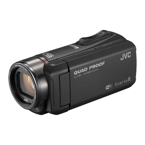
JVC GZ-EX210BUA User manual

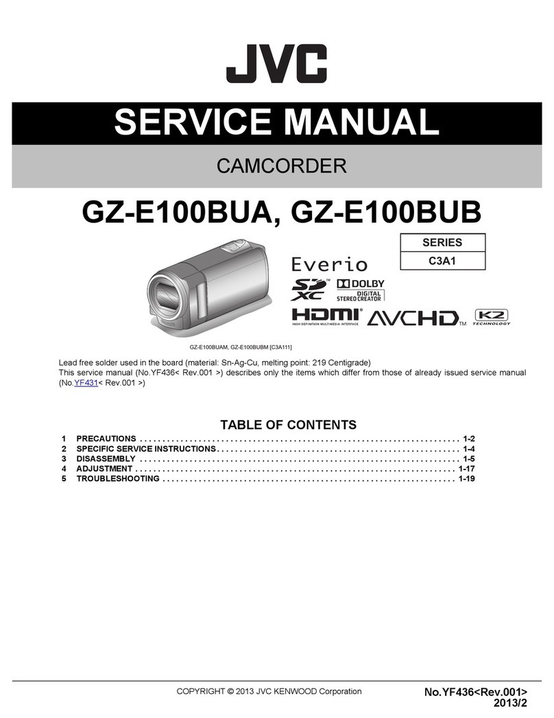
SERVICE MANUAL
COPYRIGHT © 2012 JVC KENWOOD Corporation No.YF412<Rev.001>
2012/3
CAMCORDER
YF412<Rev.001>20123SERVICE MANUALEVERIO-S-HD
GZ-EX210BUA, GZ-EX210BUB
COPYRIGHT © 2012 JVC KENWOOD Corporation
Lead free solder used in the board (material: Sn-Ag-Cu, melting point: 219 Centigrade)
This service manual (No.YF412< Rev.001 >) describes only the items which differ from those of already issued service manual
(No.YF400< Rev.001 >)
TABLE OF CONTENTS
1 PRECAUTIONS . . . . . . . . . . . . . . . . . . . . . . . . . . . . . . . . . . . . . . . . . . . . . . . . . . . . . . . . . . . . . . . . . . . . . . . 1-2
2 SPECIFIC SERVICE INSTRUCTIONS . . . . . . . . . . . . . . . . . . . . . . . . . . . . . . . . . . . . . . . . . . . . . . . . . . . . . . 1-4
3 DISASSEMBLY . . . . . . . . . . . . . . . . . . . . . . . . . . . . . . . . . . . . . . . . . . . . . . . . . . . . . . . . . . . . . . . . . . . . . . . 1-5
4 ADJUSTMENT . . . . . . . . . . . . . . . . . . . . . . . . . . . . . . . . . . . . . . . . . . . . . . . . . . . . . . . . . . . . . . . . . . . . . . . 1-17
5 TROUBLESHOOTING . . . . . . . . . . . . . . . . . . . . . . . . . . . . . . . . . . . . . . . . . . . . . . . . . . . . . . . . . . . . . . . . . 1-19
SERIES
C2A3
GZ-EX210BUAM, GZ-EX210BUBM [C2A303]

1-2 (No.YF412<Rev.001>)
SECTION 1
PRECAUTIONS
1.1 SAFETY PRECAUTIONS
Prior to shipment from the factory, JVC products are strictly
inspected to conform with the recognized product safety and
electrical codes of the countries in which they are to be
sold.However,in order to maintain such compliance, it is equally
important to implement the following precautions when a set is
being serviced.
1.1.1 Precautions during Servicing
(1) Locations requiring special caution are denoted by labels
and inscriptions on the cabinet, chassis and certain parts of
the product.When performing service, be sure to read and
comply with these and other cautionary notices appearing
in the operation and service manuals.
(2) Parts identified by the symbol and shaded ( ) parts
are critical for safety.
Replace only with specified part numbers.
NOTE :
Parts in this category also include those specified to
comply with X-ray emission standards for products
using cathode ray tubes and those specified for
compliance with various regulations regarding
spurious radiation emission.
(3) Fuse replacement caution notice.
Caution for continued protection against fire hazard.
Replace only with same type and rated fuse(s) as
specified.
(4) Use specified internal wiring. Note especially:
• Wires covered with PVC tubing
• Double insulated wires
• High voltage leads
(5) Use specified insulating materials for hazardous live parts.
Note especially:
• Insulation Tape
• PVC tubing
•Spacers
• Insulation sheets for transistors
• Barrier
(6) When replacing AC primary side components (transformers,
power cords, noise blocking capacitors, etc.) wrap ends of
wires securely about the terminals before soldering.
Fig.1-1-1
(7) Observe that wires do not contact heat producing parts
(heatsinks, oxide metal film resistors, fusible resistors, etc.)
(8) Check that replaced wires do not contact sharp edged or
pointed parts.
(9) When a power cord has been replaced, check that 10-15
kg of force in any direction will not loosen it.
Fig.1-1-2
(10) Also check areas surrounding repaired locations.
(11) Products using cathode ray tubes (CRTs)
In regard to such products, the cathode ray tubes them-
selves, the high voltage circuits, and related circuits are
specified for compliance with recognized codes pertaining
to X-ray emission. Consequently, when servicing these
products, replace the cathode ray tubes and other parts
with only the specified parts. Under no circumstances at-
tempt to modify these circuits.Unauthorized modification
can increase the high voltage value and cause X-ray emis-
sion from the cathode ray tube.
(12) Crimp type wire connector
In such cases as when replacing the power transformer in
sets where the connections between the power cord and
power trans former primary lead wires are performed using
crimp type connectors, if replacing the connectors is un-
avoidable, in order to prevent safety hazards, perform
carefully and precisely according to the following steps.
•Connector part number: E03830-001
•Required tool: Connector crimping tool of the proper
type which will not damage insulated parts.
•Replacement procedure
a) Remove the old connector by cutting the wires at a
point close to the connector.Important: Do not
reuse a connector (discard it).
Fig.1-1-3
b) Strip about 15 mm of the insulation from the ends
of the wires. If the wires are stranded, twist the
strands to avoid frayed conductors.
Fig.1-1-4
c) Align the lengths of the wires to be connected.
Insert the wires fully into the connector.
Fig.1-1-5
d) As shown in Fig.1-1-6, use the crimping tool to crimp
the metal sleeve at the center position. Be sure to
crimp fully to the complete closure of the tool.
Fig.1-1-6
e) Check the four points noted in Fig.1-1-7.
Fig.1-1-7
Power cord
cut close to connector
15 mm
Connector
Metal sleeve
1.25
2.0
5.5
Crimping tool
Not easily pulled free Crimped at approx. cente
r
of metal sleeve
Conductors extended
Wire insulation recessed
more than 4 mm
(No.YF412<Rev.001>)1-3
1.1.2 Safety Check after Servicing
Examine the area surrounding the repaired location for damage
or deterioration. Observe that screws, parts and wires have been
returned to original positions, Afterwards, perform the following
tests and confirm the specified values in order to verify
compliance with safety standards.
(1) Insulation resistance test
Confirm the specified insulation resistance or greater
between power cord plug prongs and externally exposed
parts of the set (RF terminals, antenna terminals, video and
audio input and output terminals, microphone jacks,
earphone jacks, etc.).See table 1 below.
(2) Dielectric strength test
Confirm specified dielectric strength or greater between
power cord plug prongs and exposed accessible parts of
the set (RF terminals, antenna terminals, video and audio
input and output terminals, microphone jacks, earphone
jacks, etc.). See Fig.1-1-11 below.
(3) Clearance distance
When replacing primary circuit components, confirm
specified clearance distance (d), (d') between soldered
terminals, and between terminals and surrounding metallic
parts. See Fig.1-1-11 below.
Fig.1-1-8
(4) Leakage current test
Confirm specified or lower leakage current between earth
ground/power cord plug prongs and externally exposed
accessible parts (RF terminals, antenna terminals, video
and audio input and output terminals, microphone jacks,
earphone jacks, etc.).
Measuring Method: (Power ON) Insert load Z between
earth ground/power cord plug prongs and externally
exposed accessible parts. Use an AC voltmeter to
measure across both terminals of load Z. See Fig.1-1-9
and following Fig.1-1-12.
Fig.1-1-9
(5) Grounding (Class 1 model only)
Confirm specified or lower grounding impedance between
earth pin in AC inlet and externally exposed accessible
parts (Video in, Video out, Audio in, Audio out or Fixing
screw etc.).Measuring Method:
Connect milliohm meter between earth pin in AC inlet and
exposed accessible parts. See Fig.1-1-10 and grounding
specifications.
Fig.1-1-10
Fig.1-1-11
Fig.1-1-12
NOTE:
These tables are unofficial and for reference only. Be sure to confirm the precise values for your particular country and locality.
Chassis
Power cord
primary wire
d'
d
ab
c
V
A
Externally
exposed
accessible part
Z
Exposed accessible part
Grounding Specifications
AC inlet
Region
USA & Canada
Europe & Australia
Grounding Impedance (Z)
Z 0.1 ohm
Z 0.5 ohm
Earth pin
MIlli ohm meter
AC Line Voltage Region
Japan
Europe & Australia
R 1 M /500 V DC
USA & Canada 1 M R 12 M /500 V DC
R 10 M /500 V DC
Insulation Resistance (R)Dielectric Strength Clearance Distance (d), (d')
100 V
100 to 240 V
110 to 130 V
110 to 130 V
200 to 240 V
AC 1 kV 1 minute
AC 1.5 kV 1 minute
AC 1 kV 1 minute
(Class )
(Class )
AC 3 kV 1 minute
AC 1.5 kV 1 minute
d, d' 3 mm
d, d' 4 mm
d, d' 3.2 mm
d' 8 m m (Power cord)
d' 6 m m (Primary wire)
d 4 m m
AC Line Voltage Region
Japan
Europe & Australia
USA & Canada
Load Z Leakage Current (i) a, b, c
100 V
110 to 130 V
110 to 130 V
220 to 240 V
i 1 mA rms
i 0.5 mA rms
i 0.7 mA peak
i 2 mA dc
i 0.7 mA peak
i 2 mA dc
Exposed accessible parts
Antenna earth terminals
Other terminals
1
1.5
2
50
0.15

1-4 (No.YF412<Rev.001>)
SECTION 2
SPECIFIC SERVICE INSTRUCTIONS
2.1 DIFFERENCE LIST
MODEL GZ-EX210BUA GZ-EX210BUB
AC CORD IRAM TYPE BRAZIL TYPE

(No.YF412<Rev.001>)1-5
SECTION 3
DISASSEMBLY
3.1 Disassembly procedure
Fig.3-1-1

1-6 (No.YF412<Rev.001>)
Fig.3-1-2

(No.YF412<Rev.001>)1-7
Fig.3-1-3

1-8 (No.YF412<Rev.001>)
Fig.3-1-4

(No.YF412<Rev.001>)1-9
Fig.3-1-5

1-10 (No.YF412<Rev.001>)
Fig.3-1-6

(No.YF412<Rev.001>)1-11
Fig.3-1-7

1-12 (No.YF412<Rev.001>)
Fig.3-1-8

(No.YF412<Rev.001>)1-13
Fig.3-1-9

1-14 (No.YF412<Rev.001>)
Fig.3-1-10

(No.YF412<Rev.001>)1-15
Fig.3-1-11

1-16 (No.YF412<Rev.001>)
3.2 Quality point
When you assemble the unit, please check the following points for keeping the quality.
Fig.3-2-1
Between the CMOS and the MAIN, run the FPC under the mold.
(Running the FPC over the mold will result in poor contact because of
stress.)
To replace the BARRIER UNIT, open the BARRIER to check the screws.
(The screws cannot be observed with the BARRIER closed.)
Do not apply excessive shock to the CMOS ASSY.
(It is 3-demensionally adjusted using adhesive.)
Between the CMOS and the MAIN, insert the FPC before assembly.
Do not fold the FPC at the edges of the reinforcing plate and the
connector.
(The broken terminal will result in disconnection.)
When attaching the TOP COVER, properly set the rear side.
(Make sure there is no unevenness. Forcible attachment will result in
breakage.)
Do not fold the FPC protruded from the HINGE COVER.
(Repeated opening/closing the monitor will break the FPC.)
When attaching the LOWER CASE, do not damage the parts or patterns on
the MAIN PWB.(Some models have shutter lever that cannot be separated.)
To remove the TOP COVER, remove the screw on the HINGE in
addition to the 3 screws.
When attaching the TOP COVER, properly set the rear side.
When tightening the screw [1] on the TOP side, make sure there is a space
[2].
(Without the space, the TOP COVER cannot be attached.)
OK NG
OK NG

(No.YF412<Rev.001>)1-17
SECTION 4
ADJUSTMENT
4.1 PREPARATION
4.1.1 Precaution
This model is specially adjusted by using PC.
However, if parts such as the following are replaced, an
adjustment is required. The adjustment must be performed in a
Service Center equipped with the concerned facilities.
• OP BLOCK ASSEMBLY
• MONITOR ASSEMBLY
• EEP ROM (IC1003 of MAIN board)
In the event of malfunction with electrical circuits, first find a
defective portion with the aid of proper test instruments as shown
in the following electrical adjustment procedure, and then
commence necessary repair/ replacement/adjustment.
• In observing chip TP, use IC clips, etc. to avoid any stress.
Prior to replacement of chip parts (especially IC), remove the
solder completely to prevent peeling of the pattern.
• Since connectors are fragile, carefully handle them in
disconnecting and connecting the FPC.
4.1.2 Required test equipment
• Personal computer (for Windows)
• Color TV monitor
• Oscilloscope (dual-trace type, observable 100MHz or higher
frequency). The one observable 300 MHz or higher frequency
is recommended.
• Digital voltmeter
• DC power supply or AC adapter
• Frequency counter (with threshold level adjuster)
4.1.3 Tools required for adjustment
•Torque Driver
Be sure to use to fastening the mechanism and exterior parts
because those parts must strictly be controlled for tightening
torque.
•Bit
This bit is slightly longer than those set in conventional torque
drivers.
•Tweezers
To be used for removing and installing parts and wires.
•Chip IC Replacement Jig
To be used for adjustment of the camera system.
•Cleaning Cloth
To be used to wipe down the LCD screen and the optical lens
surface.
•INF Adjustment Lens
To be used for adjustment of the camera system. For the
usage of the INF adjustment lens, refer to the Service Bulletin
No. YA-SB-10035 and No. YA-SB-10223.
•INF Adjustment Lens Holder
To be used together with the Camera stand for operating the
Videocamera in the stripped-down condition such as the sta-
tus without the exterior parts or for using commodities that are
not yet conformable to the interchangeable ring. For the usage
of the INF lens holder, refer to the Service Bulletin No. YA-SB-
10035.
•Mini Stand
To be used together with the INF adjustment lens holder. For
the usage of the Mini stand, refer to the Service Bulletin No.
YA-SB-10035.
•Light Box Assembly
To be used for adjustment of the camera system. For the
usage of the Light box assembly, refer to the Service Bulletin
No. YA-SB-10035 and No. YA-SB-10218.
•Jig Connector Cable
Connected to JIG CONNECTOR of the main board and used
for electrical adjustment, etc.
•PC Cable
To be used to connect the Videocamera and a personal computer
with each other when a personal computer issued for adjustment.
•Service Support System
To be used for adjustment with a personal computer. Software
can be downloaded also from JS-net.
Torque Driver
YTU94088
Bit
YTU94088-003
Chip IC Replacement Jig
PTS40844-2
Tweezers
P-895
Cleaning Cloth
KSMM-01
INF Adjustment Lens Holder
YTU94087
Mini Stand
YTU93108
Jig Connector Cable
YTU43192
PC Cable
QAM0099-002
Service Support System
YTU94057-134
(Software)
INF Adjustment Lens
YTU92001E
Light Box Assembly
YTU93096B

1-18 (No.YF412<Rev.001>)
4.2 JIG CONNECTOR CABLE CONNECTION
Connection procedure
Remove the 4 screws (1-4), and then remove the TOP COVER
ASSY.
TOP COVER ASSY
CN9003
MENU
SERVICE SUPPORT SYSTEM
JIG
CONNECTOR
CABLE
(Software)
PERSONAL COMPUTER
PC CABLE
3
2
1
4
3
2

(No.YF412<Rev.001>)1-19
SECTION 5
TROUBLESHOOTING
This service manual does not describe TROUBLESHOOTING.

<BOARD INTERCONNECTIONS>
yf400_y10986001a_20111216_ver0.1
1
CN601
CN201
CN9004
OP DRV
LCD PANEL
CN4602
1 ZOOM02_SUB
2 ZOOM03_SUB
3 ZOOM04_SUB
4 ZOOM01_SUB
5 FOCUS02_SUB
6 FOCUS03_SUB
7 FOCUS04_SUB
8 FOCUS01_SUB
9 F_VCC_SUB
10 F_LED_SUB
11 F_PTR_AD
12 Z_VCC_SUB
13 Z_LED_SUB
14 Z_PTR_AD
FOCUS02_SUB
Z_LED_SUB
FOCUS03_SUB
OPDRV_PSX
FOCUS01_SUB
F_VCC_SUB
ZOOM02_SUB
FOCUS04_SUB
ZOOM03_SUB
ZOOM04_SUB
ZOOM01_SUB
OPDRV_IN_F
OPDRV_IN_Z
GND
OPDRV_SDA
TO MAIN PWB
40P_DET_L
39V_OUT
38GND
37AU_SIG/L
36AU_SIG/R
35LIT_3.0V
34GND
33GND
32GND
31GND
30GND
29GND
28GND
27D_GYRO_CLK
26D_GYRO_CS
25REG_2.8V
24D_GYRO_OUT
23D_GYRO_IN
22ADP_DC
21ADP_DC
20ADP_DC
19ADP_DC
18ADP_DC
17BATT+
16BATT+
15BATT+
14BATT+
13BATT+
12BATT+
11BATT+
10BATT+
9LI_CHRG
8T_BATT
7D_BATT
6BATT_L
5KEY_A
4GND
3AL_2.8V
2PWR_LED
1ACES_LED
CN9007
1 SPK+
2 SPK-
CN9008
1 INT_R
2 M_GND
3 M_GND
4 INT_L
5 M_GND
6 M_GND
CN451
1GND
2DOM2_A
3DOP2_A
4GND
5DOM3_A
6DOP3_A
7GND
8DCKM_A
9DCKP_A
10GND
11SCLK
12
GND
13
HD_CMOS
14
VD_CMOS
15
CMOS_OUT
16
CMOS_CS
17
CMOS_CLK
18
CMOS_RST
19
GND
20
CAM_2.7V
21
CAM_2.7V
22
CAM_1.8V
23
CAM_1.8V
24GND
CN9014
1
MENU/POWER_SW
2GND
3XUSBHOST
4GND
5
USBDN
6USBDP
7GND
8VBUS
9VBUS
10
GND
11
HDMI_HP
12
TDMS_REG5V
13
HDMI_SDA
14
HDMI_SCL
15
HDMI_CEC
CN9012
1
2
3
4
5
6
7
8
9
10
11
12
13
14
15
16
17
18
19
20
21
22
23
24
25
26
27
28
29
30
31
32
33
34
CN701
1 REG_LED/REG_5.0V
2 REG_LED/REG_5.0V
3BL_CTL1/BL_FBI
4 M_RVS
5 GND
6 LCD_DATA
7 LCD_CLK
8 LCD_CS
9 LCD_RST
10 REG_1.8V
11 REG_2.8V
12 LCD_HD0
13 LCD_VD0
14 GND
15 GND
16 LCD_CLK0
17 GND
18 LCD_GO_7
19 LCD_GO_6
20 LCD_GO_5
21 LCD_GO_4
22 LCD_GO_3
23 LCD_GO_2
24 LCD_GO_1
25 LCD_GO_0
26 GND
27 TP_VDD
28 TP_SEL1
29 TP_SEL2
30 TP_X
31 TP_Y
32 GND
33 MONI_SW
34 AL_2.8V
CN702
1VCOM
2RST
3CS
4SDA
5SCL
6HSYNC
7VSYNC
8
DCLK
9NC(GND)
10D7
11D6
12D5
13D4
14D3
15D2
16D1
17D0
18GND
19NC(GND)
20VDD
21VDDIO
22DVDD
23NC(GND)
24CP1P
25CP1M
26CP2P
27CP2M
28VINT1
29CP3P
30CP3M
31
CP4P
32CP4M
33VGH
34VGL
35AGND
36FRP
37VCOMDC
38VCAC
39VCOM
CN703
1
2
3
4
5
6
7
8
1
2
3
4
5
6
7
8
9
10
11
12
13
14
15
16
17
18
CN203
1
2
3
4
5
6
7
8
9
10
11
12
13
14
15
CN9006
1 REG_5.0V
2 LD_KSODE
3
4
5
6
INT_L
INT_R
M_GND
SPK-
SPK
GND
AU_SIGRM
L_MUTE
AUDIO_CLK
AUDIO_CS
AUDIO_OUT
AOMCLK
AIOBCK
AIOLRCK
AOBD
AIBD
AUDIO_PD_L
V_OUT
SYIN
REG_5.0V
REG_2.8V
REG_1.8V
LAMP_ON
OP_THRMO
CN9013
1
2
3
4
5
6
7
8
9
10
11
12
13
14
15
16
17
18
19
20
21
22
23
24
REG_SD
SDCD0
SDCMD0
SDCLK0
SD2_DAT[0-7]
SD2_CLK
SD2_CMD
REG_3.3V
GND
GND
CN9003
JIG CONN
1 CPU_TDO
2 CPU_TMS
3 CPU_NTRST
4REG_2.8V
5UATXD0
6IF_TX
7JTAG_SEL1
8 SYS_SWDIO
9 SYS_SWCLK
10 FLASH_T2R_TX
11 BOOT
12 BOOT_SEL_1
13 SFLASH_IF_DI
14 CPU_RTCK
15 GND
16 CPU_TCK
17 CPU_TDI
18 MBE_SRST
19 UARXD0
20 SD2POWER
21 IF_RX
22 SYS_RSTL
23 SFLASH_IF_CS
24 GND
25 GND
26 FLASH_T2R_RX
27 SFLASH_IF_CLK
28 SFLASH_IF_DO
29 SDWP0
30 AL_2.8V
OPDRV_SCL
REG_5.0V
REG_2.8V
SD2POWER
UATXDO
MBE_OUT
SD2_CMD
LCD_CLKO
DOM0_A
D_GYRO_IN
IF_TX
SFLASH_IF_CS
AIOLRCK
HDMI_SDA
LCD_RST
D_GYRO_CS
REG_2.8V
OPDRV_PSX
OPDRV_SDA
TMDS_D1
HDMI_CEC
DOP1_C
SFLASH_IF_DI
AIBD
USBDP
LCD_DATA
REG_1.8V
TMDS_CLK
DOP2_C
XUSBHOST
MENU
TP_SEL1
TMDS_REG5V
SDWP0
DOM2_C
WB_E
SDCMD0
CPU_TCK
GND
FLSH_RST
F_PTR_AD
AUDIO_OUT
TMDS_D2-
CPU_TDO
CMOS_CS
AUDIO_CS
CMOS_RST
HD_CMOS
DCKM_A
DOM3_A
REG_3.3V
DOM2_A
HDMI_HPD
LD_KSODE
MBE_EEP_CS
TP_X
DOP0_A
SDWP0
MBE_EEP_OUT
KEY_A
DOM1_C
MBE_CS
ZOOM_SW
TRIG_SW
MBE_IN
LCD_VDO
DOM0_C
SD2_DAT[0-7]
JTAG_SEL1
UARXDO
AIOBCK
SD2_CLK
REG_SD
SD2POWER
P_DET_L
D_GYRO_OUT
LAMP_ON
LCD_GO_[0-7]
DOP2_A
IF_RX
TMDS_D2
SFLASH_IF_DO
AOBD
USBDN
LCD_CS
SD0_DAT[0-3]
TMDS_D0
OP_THRMO
OPDRV_SCL
TMDS_D1-
OPDRV_IN_F
DOP3_C
SFLASH_IF_CLK
VBUS
LCD_CLK
TMDS_D0-
DOP0_C
OPDRV_IN_Z
SDCD0
Z_PTR_AD
HDMI_SCL
CPU_RTCK
TP_SEL2
SDCLK0
TMDS_CLK-
SD0_DAT[0-3]
MBE_RST
CPU_NTRST
CPU_TMS
CMOS_CLK
AUDIO_CLK
CPU_TDI
CMOS_OUT
AUDIO_PD_L
DCKP_A
VD_CMOS
SCLK
DOM3_C
MBE_SRST
DOP3_A
TP_VDD
MBE_EEP_CLK
TP_Y
DOM1_A
SYIN
BOOT_SEL_1
MBE_EEP_IN
REG_5.0V
KEY_B
DOP1_A
MBE_CLK
LCD_HDO
AOMCLK
MBE_EEP_OUT
GND
REG_CTL2
SYS_SWCLK
PEN2
L_MUTE
MBE_EEP_IN
D_BATT
SYS_RSTL
VBUS
REG_PEN1
MONI_SW
BATT_L
USUS
REG_THMEN
LIT_3.0V
USUS
REG_2.8V
CHARGE_ICONT
M_RVS
ADP_DC
CHARGE_ICONT
T_BATT
BL_FBI
BATT
GND
MBE_RST
AL_2.8V
REG_CTL
REG_1.2V
CAM_1.8V
FLSH_RST
AL_5.0V
REG_LED
CAM_2.7V
REG_UOK
REG_UOK
PWR_SW
REG_DOK
V_BATT
REG_3.3V
MBE_IN
REG_CEN
DONE UNREGCHK
MBE_CS
DONE
T_BATT
V_BATT
FLT
ACES_LED
BOOT
MBE_CLK
REG_CTL
OT
REG_1.8V
UNREGCHK
PWR_LED
REG_DOK
MBE_OUT
FLASH_T2R_RX
REG_CHG_DET
MBE_EEP_CS AL_2.8V
PEN2
FLASH_T2R_TX
FLT
MBE_EEP_CLK REG_2.8V
REG_PEN1
SYS_SWDIO
REG_CEN
OT
REG_1.1V
REG_SCL
REG_SDA
LI_CHRG
REG_CHG_DET
REG_THMEN
T_CTL1
T_CTL2
REG_3.3VCTL
REG_1.0VCTL
LCD_DATA
LCD_CLK
LCD_CS
LCD_RST
WIFI_SPI_CK
WIFI_SPI_DO
WIFI_SPI_DI
WIFI_RX
WIFI_TX
WIFI_RST
MOD_DP
DRXD
WIFI_SPI_DI
REG_3.3VCTL
DTXD
WIFI_USBDPWIFI_ATTACH
WIFI_SPI_CK
WIFI_USBDN
REG_1.0VCTL
MOD_RST
WIFI_SPI_DO
MOD_DN
REG_3.3V
WIFI_RX
REG_1.8V
MOD_3.3V
WIFI_WKUP
WIFI_TX
WIFI_SPI_CS
REG_1.2V
WIFI_SPI_CS
WIFI_ATTACH
WIFI_WKUP
WIFI_USBDP
WIFI_USBDN
WIFI_KENTO
WIFI_RST
WIFI_KENT0
QGF0543F3-12X
CN9015
1MOD_RST
2GND
3GND
4MOD_DN
5MOD_DP
6GND
7GND
8MOD_1.5V
9MOD_1.5V
10 MOD_3.3V
11 MOD_3.3V
12 MOD_3.3V
MOD_1.5V
REG_1.1V
CN9001
40
39
38
37
36
35
34
33
32
31
30
29
28
27
26
25
24
23
22
21
20
19
18
17
16
15
14
13
12
11
10
9
8
7
6
5
4
3
2
1
CN9002
1 GND
2 TRIG_SW
3 HALF_SW
4 FULL_SW
5 ZOOM_SW
6REG_2.8V
REG_5.0V
REG_SDA
REG_SCL
T_CTL1
T_CTL2
AU_SIGLM
D_GYRO_CLK
QGF0321F1-33X
CN9011
1
2
3
4
5
6
7
8
9
10
11
12
13
14
15
16
17
18
19
20
21
22
23
24
25
26
27
28
29
30
31
32
33
QGF0543F3-12X
1
2
3
4
5
6
7
8
9
10
11
12
GND
1GND
2GND
3TMDS_CLK-
4TMDS_CLK+
5GND
6GND
7TMDS_D0-
8TMDS_D0+
9GND
10GND
11TMDS_D1-
12TMDS_D1+
13GND
14GND
15TMDS_D2-
16TMDS_D2+
17GND
18GND
QGF0319F1-31X
1GND
2GND
3DOM0_A
4DOP0_A
5DOM1_A
6DOP1_A
7DOM0_C
8DOP0_C
9DOM1_C
10DOP1_C
11DOM2_C
12DOP2_C
13DOM3_C
14DOP3_C
15DCKM_A
16DCKP_A
17GND
18CLK_IN
19GND
20HD_CMOS
21VD_CMOS
22CMOS_OUT
23CMOS_CS
24CMOS_CLK
25CMOS_RST
26GND
27CAM_2.7V
28CAM_2.7V
29CAM_1.8V
30CAM_1.8V
31GND
INT MIC
SPEAKER
CMOS PWB
05
OP BLOCK(A2WN)
LED
2
SW
0
POWER ACCESS
INFO
VIDEO/
LITHIUM
DSC
BTU TERMINAL
PWB
SW
SW
POWER
REAR
LED
USB
DC JACK
A/V JACK
Trigger
OPERATION
T
ZOOM
W
SNAP
OP CONNE
W/B_E
z_vcc_SUB
F_LED_SUB
HDMI
03JACK PWB
MONITOR PWB
04
SW MENU
TOUCH
PANEL
TO LED LIGHT
LED
AUDIO
+
MAIN IF
NAND
FELIX
GND
GND
MONI
SWITCH
06
CMOS 126 PWB
CMOS 053 PWB
For IMX053 For IMX126
01MAIN PWB
OP DRV
SUBCPU
JACK PWB
CMOS PWB
+
+
FELIX
AUDIO
NAND
LCD
JIGCON
+
MAIN IF
OPERATION
REAR
+
SUBCPU
REAR
REG LCD
SUBCPU
JIG-CON
STEREO
CMOS PWB
REG
SUBCPU
REAR
+
JACK
WIFI
WIFI MODULE
WIFI
SD
SW
IS
SW
SILENT
OP THERMISTOR
PLAY
UP
DOWN
OK
TO/ FROM WIFI MODULE
Other manuals for GZ-EX210BUA
1
This manual suits for next models
1
Table of contents
Other JVC Camcorder manuals

JVC
JVC GR-D375U User manual

JVC
JVC JY-HM90 User manual

JVC
JVC GR-DVL315 User manual

JVC
JVC GR-DZ7AC User manual

JVC
JVC GY-HM650U User manual

JVC
JVC GZ-R15BE Operating and maintenance manual

JVC
JVC LYT1994-001B-M User manual

JVC
JVC GR-D228 User manual

JVC
JVC GR-D93US Administrator Guide

JVC
JVC Connected Cam GY-HC500U User manual

JVC
JVC Connected Cam GY-HC900CHE User manual

JVC
JVC GR-DX25EX User manual

JVC
JVC GR-AX880 User manual

JVC
JVC Connected Cam GY-HC550U User manual

JVC
JVC GR-SXM57 User manual

JVC
JVC Everio GZ-HM690 User manual

JVC
JVC GR-D252 User manual

JVC
JVC GR-SXM335U User manual

JVC
JVC GZ-MG50E/EK User manual

JVC
JVC GZ-HD3U User manual