JVC HR-XVC29UJ User manual

Filename [XVC29UJ_02Cov1.fm]
DVD PLAYER &
VIDEO CASSETTE RECORDER
INSTRUCTIONS
LPT0966-001A
HR-XVC29UJ
For Customer Use:
Enter below the Model No. and
Serial No. which are located on the
rear of cabinet. Retain this
information for future reference.
Model No.
Serial No.
XVC29UJ_02Cov1.fm Page 1 Monday, June 14, 2004 3:48 PM

Filename [XVC29U_03Safety.fm]
Masterpage:Left0
2EN
Page 2 14 June 2004 3:49 pm
CAUTIONS
WARNING : DANGEROUS VOLTAGE INSIDE
WARNING : TO PREVENT FIRE OR SHOCK
HAZARD, DO NOT EXPOSE THIS
UNIT TO RAIN OR MOISTURE.
CLASS 1 LASER PRODUCT
REPRODUCTION OF LABELS
WARNING LABEL INSIDE OF THE UNIT
Dear Customer,
Thank you for purchasing the JVC DVD player & VHS video
cassette recorder. Before use, please read the safety
information and precautions to ensure safe use of your new
unit.
The POWER `/!button does not completely shut off
mains power from the unit, but switches operating
current on and off. “`” shows electrical power
standby and “ !” shows ON.
CAUTION:
A DVD/VCR IS A CLASS 1 LASER PRODUCT.
HOWEVER THIS DVD/VCR USES A VISIBLE LASER
BEAM WHICH COULD CAUSE HAZARDOUS
RADIATION EXPOSURE IF DIRECTED. BE SURE TO
OPERATE THE UNIT CORRECTLY AS INSTRUCTED.
WHEN THIS DVD/VCR IS PLUGGED INTO THE
WALL OUTLET, DO NOT PLACE YOUR EYES CLOSE
TO THE OPENING OF THE DISC TRAY AND OTHER
OPENINGS TO LOOK INTO THE INSIDE OF THIS
DVD/VCR.
USE OF CONTROLS OR ADJUSTMENTS OR
PERFORMANCE OF PROCEDURES OTHER THAN
THOSE SPECIFIED HEREIN MAY RESULT IN
HAZARDOUS RADIATION EXPOSURE.
DO NOT OPEN COVERS AND DO NOT REPAIR
YOURSELF. REFER SERVICING TO QUALIFIED
PERSONNEL.
IMPORTANT
It may be unlawful to record or play back copyrighted
material without the consent of the copyright owner.
CAUTION
8When you are not using the unit for a long period
of time, it is recommended that you disconnect the
power cord from the AC outlet.
8Dangerous voltage inside. Refer internal servicing
to qualified service personnel. To prevent electric
shock or fire hazard, remove the power cord from
the AC outlet prior to connecting or disconnecting
any signal lead or aerial.
8Changes or modifications not approved by JVC
could void user’s authority to operate the
equipment.
The rating plate and safety caution are on the rear of
the unit.
This unit is produced to comply with Standard IEC
60065.
POWER SYSTEM:
This set operates on voltage of AC 110 – 220Vd, 50/60
Hz with automatic switching.
Use the conversion plug (provided) depending on the
type of your AC WALL outlet.
XVC29U_03Safety.fm Page 2 Monday, June 14, 2004 3:49 PM

Masterpage:Right-No-Heading
EN 3
Filename [XVC29U_03Safety.fm]
Page 3 14 June 2004 3:49 pm
Use only discs marked with the following.
●Manufactured under license from Dolby Laboratories.
“Dolby” and the double-D symbol are trademarks of Dolby
Laboratories.
●“DTS” and “DTS 2.0 + Digital Out” are trademarks of Digital
Theater Systems, Inc.
●Cassettes marked “VHS” (or “S-VHS”) can be used with this
unit. However, S-VHS recording is not possible with this
model.
●This model is equipped with SQPB (S-VHS QUASI
PLAYBACK) that makes it possible to play back S-VHS
recordings with regular VHS resolution.
●HQ VHS is compatible with existing VHS equipment.
●This product incorporates copyright protection technology
that is protected by method claims of certain U.S. patents and
other intellectual property rights owned by Macrovision
Corporation and other rights owners. Use of this copyright
protection technology must be authorized by Macrovision
Corporation, and is intended for home and other limited
viewing users only unless otherwise authorized by
Macrovision Corporation. Reverse engineering or disassembly
is prohibited.
When the equipment is installed in a cabinet or a shelf,
make sure that it has sufficient space on all sides to allow
for ventilation (10 cm or more on both sides, on top and
at the rear.)
When discarding batteries, environmental problems must
be considered and the local rules or laws governing the
disposal of these batteries must be followed strictly.
Failure to heed the following precautions may result in
damage to the unit, Remote or video cassette.
1. DO NOT place the unit —
— in an environment prone to extreme temperatures
or humidity.
— in direct sunlight.
— in a dusty environment.
— in an environment where strong magnetic fields are
generated.
— on a surface that is unstable or subject to vibration.
2. DO NOT block the unit’s ventilation openings or
holes.
(If the ventilation openings or holes are blocked by a
newspaper or cloth, etc., the heat may not be able to
get out.)
3. DO NOT place heavy objects on the unit or Remote.
4. DO NOT place anything which might spill on top of
the unit or Remote.
(If water or liquid is allowed to enter this equipment,
fire or electric shock may be caused.)
5. DO NOT expose the apparatus to dripping or
splashing.
6. DO NOT use this equipment in a bathroom or places
with water. Also DO NOT place any containers filled
with water or liquids (such as cosmetics or medicines,
flower vases, potted plants, cups, etc.) on top of this
unit.
7. DO NOT place any naked flame sources, such as
lighted candles, on the apparatus.
8. AVOID violent shocks to the unit during transport.
MOISTURE CONDENSATION
Moisture in the air will condense on the unit when you
move it from a cold place to a warm place, or under
extremely humid conditions—just as water droplets form
in the surface of a glass filled with cold liquid. Moisture
condensation on the head drum will cause damage to the
tape. In conditions where condensation may occur, keep
the unit turned on for a few hours to let the moisture dry.
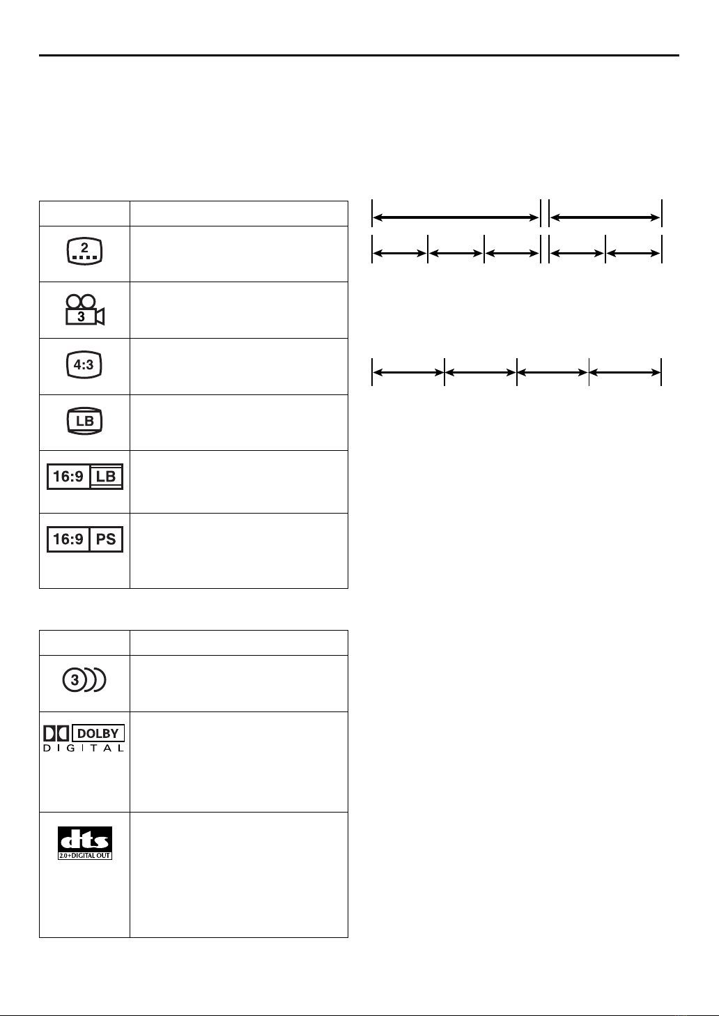
DVD
(8 cm /12 cm disc)
Video CDs
(8 cm /12 cm disc)
Audio CDs
(8 cm /12 cm disc)
SVCD
(8 cm /12 cm disc)
A
TTENTION
To mobile phone users:
Using a mobile phone in the vicinity of the unit may
cause picture vibration on the TV screen or change
the screen to a blue back display.
On placing the unit:
Some TVs or other appliances generates strong
magnetic fields. Do not place such appliance on top
of the unit as it may cause picture disturbance.
XVC29U_03Safety.fm Page 3 Monday, June 14, 2004 3:49 PM

Filename [XVC29U_04TOC.fm]
Masterpage:Left
4EN
Page 4 14 June 2004 3:50 pm
CONTENTS
DISC INFORMATION 5
About Discs ......................................................... 5
INDEX 8
INSTALLING YOUR NEW UNIT 12
Basic Connections ............................................. 12
S-VIDEO Connection (DVD deck only) ............. 13
Component Video Connection
(DVD deck only) ............................................ 14
INITIAL SETTINGS 15
Plug & Play Set .................................................. 15
Monitor Set (DVD deck) .................................... 16
Language ........................................................... 18
Clock Set ........................................................... 22
Tuner Set ........................................................... 24
OPERATIONS ON VCR DECK 26
Basic Playback .................................................. 26
Playback Features .............................................. 27
Basic Recording ................................................ 31
Recording Features ............................................ 32
Express Timer Programming .............................. 34
Satellite Auto Recording .................................... 39
OPERATIONS ON DVD DECK 40
Basic Playback .................................................. 40
Playback Features .............................................. 41
Using the on-screen bar .................................... 46
Parental Lock .................................................... 56
About MP3 Disc ................................................ 60
MP3 Playback ................................................... 61
About JPEG Disc ............................................... 63
JPEG Playback ................................................... 64
EDITING (VCR DECK) 66
Edit From A Camcorder ..................................... 66
Edit To Or From Another Video Recorder .......... 67
Dubbing (from DVD to VCR) ............................. 68
EDITING (DVD DECK) 69
Digital Audio Dubbing ...................................... 69
REMOTE 70
Remote Control Functions ................................. 70
Connecting To A Dolby Digital Decoder or
An Amplifier With A Built-in DTS
(DVD deck only) .................................... 71
SUBSIDIARY SETTINGS 72
Mode Set (VCR deck) ......................................... 72
Mode Set (DVD deck) ........................................ 75
Child Lock ......................................................... 78
Scan Mode Set (DVD deck) ............................... 78
TROUBLESHOOTING 79
QUESTIONS AND ANSWERS 84
SPECIFICATIONS 85
LIST OF TERMS 86
XVC29U_04TOC.fm Page 4 Monday, June 14, 2004 3:50 PM

Masterpage:Right0
EN 5
Filename [XVC29U_05DiscInfo.fm]
Page 5 14 June 2004 3:50 pm
DISC INFORMATION
About Discs
Playable Discs
You can use the discs with the following logos for playback
only.
●The following discs also can be played back.
• DVD-R/RW discs recorded in DVD VIDEO format and
finalized
• CD-R/RW discs recorded in Super Video CD, Video CD or
Audio CD format and finalized.
• CD-R/RW discs recorded in MP3 format in accordance with
the “ISO 9660” format. (See page 60 for details.)
• CD-R/RW discs recorded in JPEG format in accordance with
the “ISO 9660” format. (See page 63 for details.)
●Discs other than the above cannot be played back.
●Operation and audio quality of this unit are not guaranteed for
discs that do not conform to the Compact Disc specification
(CD-DA).
Before you play back a CD, check for the CD logo and read
the notes on the package to confirm that it conforms to the
Compact Disc specification.
●Depending on the intentions of the author of the software,
recording conditions of DVD discs and Video CD discs may
be restricted. Since this unit plays back discs according to the
intentions of the author of the software as indicated on the
disc, some functions may not operate as commanded.
●When switching from the first layer to the second layer of
double-layered DVD VIDEO discs, the image and sound may
be momentarily distorted. This is not a malfunction.
Unplayable Discs
The following types of discs cannot be played using this unit.
Do not attempt to play back any kind of disc that is damaged
(cracked, warped, or repaired with adhesive tape) or discs in
unusual shapes (heart-shaped, octagonal, or other forms). If such
discs are accidentally played back, it may cause noise that can
lead to speaker damage.
●CD-ROM discs (including PHOTO-CD)
●DVD AUDIO discs
●Super Audio CDs (SACD)
●DVD-RW discs recorded in VR format
●DVD-RAM
●Discs which have a region number other than “1”
Region Number
The world is divided into 6 regions for DVD VIDEO discs. DVD
VIDEO discs are assigned a region number to indicate which
region they may be played back in. A disc cannot be played
back on this unit unless the region number of the disc matches
that of the unit. The region number for this unit is “1”. Only discs
whose region number includes “1” can be played back such as
shown below.
Examples of DVD VIDEO labels which can be played back
using this unit.
Marks of discs in this instruction manual
DVD VIDEO
(8 cm /12 cm disc)
Video CD/Super Video CD
(8 cm /12 cm disc)
Audio CD
(8 cm /12 cm disc)
CD-DA
files
Allows operation
with a DVD VIDEO
disc.
Allows operation
with a Audio CD
disc.
Allows operation
with a Video CD
disc.
Allows operation
with a SVCD disc.
Allows operation
with a disc
including MP3 files.
Allows operation
with a disc
including JPEG files.
XVC29U_05DiscInfo.fm Page 5 Monday, June 14, 2004 3:51 PM

Filename [XVC29U_05DiscInfo.fm]
Masterpage:Left+
6EN
Page 6 14 June 2004 3:50 pm
DISC INFORMATION (cont.)
DVD VIDEO Marks
Sometimes marks are printed on a DVD disc and/or on its
packaging to indicate information regarding the contents and
functions of a disc. Check marks indicating the contents and
functions of a disc. Note, however, that in some cases a disc
may not include a mark even for a function it supports.
Marks related to video
Marks related to audio
File Structure of Discs
DVD VIDEO
Typically, DVD VIDEO discs are made up of larger units called
“titles”. Each title has a number (title number) that can be used
to select desired titles. Titles are further divided into units called
“chapters”. Each chapter has a number (chapter number) that
can also be used to select desired chapters. Note that some discs
are not divided into titles and chapters.
Audio CD/Video CD
Typically, Audio CD discs are divided into separate tracks each
containing one song. Each track is assigned a number. For
example, the third track is Track 3. The same is true for Video
CD discs.
NOTE:
Video CD discs that support Playback Control (PBC)
The still image or motion image which follows a menu screen is
called a “scene”. Each scene has a scene number.
For more details, refer to “Locating a desired scene using the
menu of the Video CD with PBC” (墌pg. 41).
Mark Description
Number of subtitles
Number of angles
Recorded under the standard 4:3 aspect
ratio
Screen includes black bands at top and
bottom of image which has a standard 4:3
aspect ratio (letter box)
Video playback is in Wide video mode
(16:9) on wide televisions, but in letter
box on televisions with standard 4:3
aspect ratio.
Video playback is in Wide video mode
(16:9) on wide televisions, but pan and
scan is used on televisions with standard
4:3 aspect ratio (either the left or right side
of the image is cut-out).
Mark Description
Number of audio tracks
Dolby Digital mark
Dolby Laboratories has developed a
digital surround system for the home. This
mark indicates that you may enjoy 5.1-
channel audio (front left and right, center,
rear left and right, and a channel for LFE
(Low-Frequency Effects)).
DTS (Digital Theater System)
The DTS decoder on this unit enables you
to enjoy DTS audio with the connected
TV’s speakers by converting 5.1 channel
audio signals into 2 channel signals (DTS
Down Mixing). The decoder also outputs
the original DTS 5.1 channel audio
signals from the DIGITAL AUDIO OUT
connector on this unit.
Title 1 Title 2
Chapter 1 Chapter 2Chapter 1Chapter 3Chapter 2
Track 1 Track 4Track 3Track 2
XVC29U_05DiscInfo.fm Page 6 Monday, June 14, 2004 3:51 PM

Masterpage:Right-No-Heading
EN 7
Filename [XVC29U_05DiscInfo.fm]
Page 7 14 June 2004 3:50 pm
Placing a Disc
1Open the disc tray.
Press OPEN/CLOSE (x) on the DVD deck to open the
disc tray.
●Pressing the button again closes the disc tray.
●Do not block the disc tray with your hand while it is opening
or closing as this may result in hardware failure.
●Do not place unplayable discs or any object other than a disc
in the disc tray.
●Do not press down strongly on the disc tray or place any
heavy objects on it.
2Place the disc.
Place the disc in the disc tray
with the label side facing up.
●Since disc size changes depending
on the disc to be played back, be
sure to correctly align the disc with
the grooves for its size. If the disc is
not in its groove, it may be
scratched or otherwise damaged.
●To insert an 8 cm disc, place it
according to the inner groove.
Care and Handling of Discs
How to handle discs
When handling a disc, do
not touch the surface of the
disc. Since discs are made
of plastic, they are easily
damaged. If a disc gets
dirty, dusty, scratched or
warped, the images and
sound will not be picked up
correctly, and such a disc may cause the unit to malfunction.
Label side
Do not damage the label side, stick paper to or use any adhesive
on its surface.
Storage
Make sure that discs are kept in their cases. If discs are piled on
top of one another without their protective cases, they can be
damaged. Do not put discs in a location where they may be
exposed to direct sunlight, or in a place where the humidity or
temperature is high. Avoid leaving discs in your car!
Maintenance of discs
If there are fingerprints or other dirt
adhering to a disc, wipe with a soft dry
cloth, moving from the center outwards.
If a disc is difficult to clean, wipe with a
cloth moistened with water. Never use
record cleaners, petrol, alcohol or any
anti-static agents.
x
CAUTION
Sometimes during playback, noise or images may be
garbled. This is sometimes due to the disc. (It may not be up
to industry standards.)
These symptoms are caused by the discs, not by the
malfunction of the unit.
XVC29U_05DiscInfo.fm Page 7 Monday, June 14, 2004 3:51 PM

Filename [XVC29U_06Index.fm]
Masterpage:Left0
8EN
Page 8 14 June 2004 3:51 pm
INDEX
FRONT VIEW
APower Button (POWER (1)) 墌pg. 16
BVCR Indicator 墌pg. 26, 31
CVHS Cassette Loading Slot
DVCR/DVD Button 墌pg. 26, 31, 40
EDisc Tray
FStop Button (STOP (8)) 墌pg. 26, 31, 40
GDVD Indicator 墌pg. 40
HPlay Button (PLAY (4)) 墌pg. 26, 40
IDVD Open/Close Button (OPEN/CLOSE (x))
墌pg. 40
JVHS Eject Button (EJECT (x)) 墌pg. 26, 31
KVideo/Audio Input Connectors (VIDEO/AUDIO)
墌pg. 66
LRemote Sensor
MFront Display Panel 墌pg. 9
NRecord Button (REC (7)) 墌pg. 31
ORewind Button (REW (3)) 墌pg. 26, 27, 42
PFast Forward Button (FF (5)) 墌pg. 26, 27, 42
QChannel Button (CH +/–) 墌pg. 31
RProgressive Scan Button (PROGRESSIVE SCAN)
墌pg. 78
XVC29U_06Index.fm Page 8 Monday, June 14, 2004 3:52 PM

Masterpage:Right-No-Heading
EN 9
Filename [XVC29U_06Index.fm]
Page 9 14 June 2004 3:51 pm
REAR VIEW
ARegion Number Label 墌pg. 5
BAC Power Cord 墌pg. 12
CS-video Output Connector (S VIDEO OUTPUT)*
墌pg. 13
DAudio/Video Output Connectors (AUDIO/
VIDEO OUTPUT) 墌pg. 12, 13, 14, 67
EAntenna Input Connector (VHF/UHF IN)
墌pg. 12
* These connectors are only for DVD deck.
FDigital Audio Output Connector
(DIGITAL AUDIO OUT)* 墌pg. 69
GComponent Video Output Connectors
(COMPONENT VIDEO OUT)* 墌pg. 14
HAudio Output Connectors (AUDIO OUTPUT
(L/R))*
IRemote Pause Connector 墌pg. 66
JAntenna Output Connector (VHF/UHF OUT)
墌pg. 12
FRONT DISPLAY PANEL
AOperation Mode Indicators
BChannel/Clock
Auxiliary Input Mode Display (F-1) (VCR deck
only)
Counter Display (VCR deck)
Tape Speed (SP/EP) (VCR deck only)
Multi-information window* (DVD deck)
* The current group/title/track/chapter number(s), time and status
information.
CVCR Indicator 墌pg. 32
DProgressive Mode Indicator 墌pg. 78
E“Timer” Indicator (VCR deck only) 墌pg. 35
FSatellite Auto Recording Indicator (N) (VCR deck
only) 墌pg. 39
XVC29U_06Index.fm Page 9 Monday, June 14, 2004 3:52 PM

Filename [XVC29U_06Index.fm]
Masterpage:Left+
10 EN
Page 10 14 June 2004 3:51 pm
INDEX (cont.)
ON-SCREEN DISPLAY (VCR deck)
If you press ON SCREEN on the Remote when “SUPERIMPOSE” is set to “ON” (墌pg. 73), various operational
indicators appear on the TV screen.
For On-screen display for DVD deck, refer to “Using the on-screen bar” (墌pg. 46).
AOperation Mode Indicators
BTape Speed (SP/EP)
CTape Position Indicator
The tape position indicator
appears on the TV screen
when you press REW (3)
or FF (5) from the Stop
mode or perform an Index
Search. (墌pg. 28) The
position of “q” in relation to
“B” (beginning) or “E” (end)
shows you where you are
on the tape.
NOTE:
Depending on the type of tape being used, the tape position
indicator may not appear correctly.
DIndex number 墌pg. 28
ETape Remaining Time Indicator 墌pg. 33
FCounter Display
GAudio Mode Display 墌pg. 30
HSAP Indicator 墌pg. 33
IStereo Program Indicator 墌pg. 33
JDay/Clock Display
KChannel Position Number/Auxiliary Input
Indicator (F-1)
L“Cassette Loaded” Mark
Beginning End
To recall an indication
APress ON SCREEN.
●All indications corresponding to the current status are
displayed for 5 seconds. After that, the counter
information and RECORD/PAUSE if in the Record
Pause mode, remain on the screen.
BPress ON SCREEN again to clear the display.
●The RECORD/PAUSE indication remains on the screen.
XVC29U_06Index.fm Page 10 Monday, June 14, 2004 3:52 PM

Masterpage:Right-No-Heading
EN 11
Filename [XVC29U_06Index.fm]
Page 11 14 June 2004 3:51 pm
REMOTE
AVCR Button 墌pg. 26, 31
BTV/VCR/DVD switch 墌pg. 16
CMenu Button (MENU) 墌pg. 41
DSP/EP Button 墌pg. 31
Top Menu Button (TOP MENU) 墌pg. 41
EStop Time Button (STOP +/–) 墌pg. 34
On-Screen Button (ON SCREEN) 墌pg. 10, 46
FStart Time Button (START +/–) 墌pg. 34
Repeat Button (REPEAT) 墌pg. 48, 62 65
Zooming Button (ZOOM) 墌pg. 43
GNumber Keys 墌pg. 25, 31, 62
HDaily Button (DAILY) 墌pg. 35
IReset Button (C.RESET) 墌pg. 33
Cancel Button (CANCEL) 墌pg. 37
10 Button
JPlay Button (PLAY (4)) 墌pg. 26, 40
KRewind Button (REW (3)) 墌pg. 26, 27, 42
LStop Button (STOP (8)) 墌pg. 26, 31, 40
MRecord Button (REC (7)) 墌pg. 31
NReverse Skip/Index Button (SKIP/INDEX (2))
墌pg. 28, 41
Review Button ( )
Ort Button 墌pg. 16
TV/VCR Channel Button (TV/VCR CH +/–)
墌See the left column
PSet Up Button (SET UP) 墌pg. 16
Q3D-Phonic Button (3D-PHONIC) 墌pg. 44
RTV Volume Button (TV VOL+/–) 墌See the left
column
SDVD Button 墌pg. 40
TPower Button (POWER (1)) 墌pg. 16, left
column
UTV Muting Button (MUTE) 墌See the left column
Audio Monitor Button (A.MONITOR)
墌pg. 30, 54, 55
VTV/VCR Button 墌pg. 32, left column
WDate Button (DATE +/–) 墌pg. 34
Subtitle Button (SUB TITLE) 墌pg. 52
Angle Button (ANGLE) 墌pg. 53
XChannel Button (CH +/–) 墌pg. 31
YProgramming Button (PROG.) 墌pg. 34
ZTimer Button (TIMER) 墌pg. 35
aWeekly Button (WEEKLY) 墌pg. 35
bProgram Check Button (PROG. CHECK)
墌pg. 36
Return Button (RETURN) 墌pg. 41
cSatellite Auto Recording Button (REC LINK)
墌pg. 39
d+10 Button
eAuxiliary Button (AUX) 墌pg. 66
fFast Forward Button (FF (5)) 墌pg. 26, 27, 42
gPause Button (PAUSE (9)) 墌pg. 27, 31
hForward Skip/Index Button (SKIP/INDEX (6))
墌pg. 28, 41
iENTER Button 墌pg. 16
jweButton 墌pg. 16
kDisplay Button (DISPLAY) 墌pg. 33
lSkip Search Button (SKIP SEARCH) 墌pg. 28
DVD Picture Button (DVD PICTURE) 墌pg. 45
Buttons with a small dot on the left side of the name (POWER
(1), TV/VCR, TV/VCR CH +/–, TV VOL+/–, MUTE) can
also be used to operate a JVC’s TV after setting the TV/VCR/
DVD switch to the left.
How To Use
Before use, insert two AA size batteries into the Remote with
the polarity ( and ) matched correctly as indicated on
the battery compartment or on the lid.
The Remote can operate most of your unit’s functions, as
well as basic functions of TV sets of JVC. (墌See the left
column)
●Point the Remote toward the remote sensor.
●The maximum operating distance of the remote control is
about 8 m.
NOTE:
If the Remote doesn’t work properly, remove its batteries,
wait a short time, replace the batteries and then try again.
XVC29U_06Index.fm Page 11 Monday, June 14, 2004 3:52 PM

Filename [XVC29U_06Index.fm]
Masterpage:Left0
12 EN
Page 12 14 June 2004 3:51 pm
INSTALLING YOUR NEW UNIT
Basic Connections
It’s essential that your unit be properly connected.
ACheck the contents.
Make sure the package contains all of the accessories
listed in “SPECIFICATIONS” on page 85.
BSituate the unit.
Place the unit on a stable, horizontal surface.
CConnect the unit to TV.
The connection method you use depends on the type of
TV you have.
RF Connection
8To connect to a TV with NO AV input connectors —
ADisconnect the TV antenna from the TV.
BConnect the TV antenna cable to the VHF/UHF IN
connector on the rear panel of the unit.
CConnect the supplied RF cable between the VHF/UHF
OUT connector on the rear panel of the unit and the
TV’s antenna terminal.
AV Connection
8To connect to a TV with AV input connectors —
AConnect the antenna, unit and TV as per “RF
Connection”.
BConnect an optional audio/video cable between the
AUDIO/VIDEO OUTPUT connectors on the rear
panel of the unit and the TV’s audio/video input
connectors.
●Set your TV to AV mode.
●For switching the TV’s mode, refer to the instruction manual of
your television.
●To obtain high-quality pictures, you can also use the S-VIDEO
connection or Component Video Connection. (DVD deck
only) (墌pg. 13, 14)
DConnect the unit to power source.
Plug the end of the AC power cord into an AC outlet. This
unit performs Plug & Play Set automatically. (墌pg. 15)
●The clock and tuner channels will automatically be set when
the antenna is connected and when the AC power cord is first
connected to an AC outlet. (If “AUTO” and the channel
indicator are displayed on the front display panel before the
unit is powered on, the clock and tuner channels are being set
automatically. Wait for the time to be displayed on the front
display panel before turning on the unit.)
ESet the VCR channel.
The VCR channel is the channel on which you can watch
the picture from the unit on the TV when only using RF
connection.
With RF connection, set the VCR channel to “3 CH” or
“4 CH”.
●The VCR channel is preset to “3 CH”. Set to “4 CH” if the
Channel 3 is used for broadcasting in your area.
With AV connection, set the VCR channel to “– CH” (off).
To set the VCR channel, perform the following steps:
APress POWER (1) to turn off the unit, then press
STOP (8) on the unit for more than 5 seconds. “3 CH”
appears on the front display panel.
BPress CH +/– on the Remote to select “3 CH”, “4 CH”
or “– CH” (off), then press ENTER.
THESE STEPS MUST BE COMPLETED BEFORE ANY
VIDEO OPERATION CAN BE PERFORMED.
Antenna or Cable
Matching transformer
(not supplied)
Coaxial cable
VHF/UHF OUT
VIDEO OUTPUT
AC Outlet
RF cable
(supplied)
Back of unit VHF/UHF
IN
AUDIO
OUTPUT
Audio/video cable
(not supplied)
Flat feeder
TV
AC Power Cord
To 75 ohm
Terminal
To Audio/video
input connectors
Before performing the following steps:
●Make sure there is no cassette inserted in the unit.
●Make sure the unit is turned on, then press VCR/
DVD on the unit or VCR on the Remote so that the
VCR indicator lights up.
XVC29U_06Index.fm Page 12 Monday, June 14, 2004 3:52 PM

Masterpage:Right-No-Heading
EN 13
Filename [XVC29U_06Index.fm]
Page 13 14 June 2004 3:51 pm
S-VIDEO
Connection
(DVD deck only)
8To connect to a TV with S-VIDEO/AUDIO input
connectors . . .
AConnect the unit to TV.
AConnect the antenna, unit and TV as per “AV
Connection”. (墌pg. 12)
BConnect the unit’s S VIDEO OUTPUT (DVD)
connector to the TV’s S-VIDEO input connector.
BConnect the unit to power source.
Plug the end of the AC power cord into an AC outlet. This
unit performs Plug & Play Set automatically. (墌pg. 15)
●The clock and tuner channels will automatically be set when
the antenna is connected and when the AC power cord is first
connected to an AC outlet. (If “AUTO” and the channel
indicator are displayed on the front display panel before the
unit is powered on, the clock and tuner channels are being set
automatically. Wait for the time to be displayed on the front
display panel before turning on the unit.)
CSet the VCR channel to off.
APress POWER (1) to turn off the unit, then press
STOP (8) on the unit for more than 5 seconds. “3 CH”
appears on the front display panel.
BPress CH +/– on the Remote to select “– CH” (off),
then press ENTER.
NOTES:
●You can obtain high-quality S-VIDEO pictures.
●If your TV is not stereo-capable, use the unit’s AUDIO
OUTPUT connectors to connect to an audio amplifier for
Hi-Fi stereo sound reproduction.
●To operate the unit with your TV using the S-VIDEO
connection, set your TV to its AV mode. You can also use the
TV/VCR button on the unit’s Remote to set JVC TV to the AV
mode.
●For switching the TV’s mode, refer to the instruction manual of
your television.
●Only DVD picture is output from S-VIDEO OUTPUT
connector. (VCR picture is not output.)
A
TTENTION
Be sure to connect the unit’s VIDEO OUTPUT (DVD/
VCR) connector to the TV’s VIDEO input connector.
TV
To S-VIDEO input
connector
AUDIO OUTPUT
S-Video cable
(not supplied)
Audio/video
cable
(not supplied)
AC outlet
AC power
cord
Back of unit
RF cable
(supplied)
S VIDEO OUTPUT
Antenna or Cable
Matching transformer
(not supplied)
Coaxial cable
Flat feeder
VIDEO OUTPUT
To 75 ohm
Terminal
VHF/UHF
OUT
VHF/UHF
IN
Before performing the following steps:
●Make sure there is no cassette inserted in the unit.
●Make sure the unit is turned on, then press VCR/
DVD on the unit or VCR on the Remote so that the
VCR indicator lights up.
XVC29U_06Index.fm Page 13 Monday, June 14, 2004 3:52 PM

Filename [XVC29U_06Index.fm]
Masterpage:Left+
14 EN
Page 14 14 June 2004 3:51 pm
INSTALLING YOUR NEW UNIT (cont.)
Component Video
Connection
(DVD deck only)
8To connect to a TV with component video input
connectors . . .
AConnect the unit to TV.
AConnect the aerial, unit and TV as per “AV
Connection”. (墌pg. 12)
BConnect the unit’s COMPONENT VIDEO OUT
connectors to the TV’s component video input
connectors.
BConnect the unit to power source.
Plug the end of the AC power cord into an AC outlet. This
unit performs Plug & Play Set automatically. (墌pg. 15)
●The clock and tuner channels will automatically be set when
the antenna is connected and when the AC power cord is first
connected to an AC outlet. (If “AUTO” and the channel
indicator are displayed on the front display panel before the
unit is powered on, the clock and tuner channels are being set
automatically. Wait for the time to be displayed on the front
display panel before turning on the unit.)
CSet the VCR channel to off.
APress POWER (1) to turn off the unit, then press
STOP (8) on the unit for more than 5 seconds. “3 CH”
appears on the front display panel.
BPress CH +/– on the Remote to select “– CH” (off),
then press ENTER.
NOTES:
●You can obtain high-quality component video pictures.
●If your TV is not stereo-capable, use the unit’s AUDIO
OUTPUT connectors to connect to an audio amplifier for
Hi-Fi stereo sound reproduction.
●To operate the unit with your TV using the Component Video
connection, set your TV to its AV mode. You can also use the
TV/VCR button on the unit’s Remote to set JVC TV to the AV
mode.
●For switching the TV’s mode, refer to the instruction manual of
your television.
●By using the component video connection, you can view the
images in the progressive mode. For switching to the
progressive mode, refer to “Scan Mode Set (DVD deck)”
(墌pg. 78).
A
TTENTION
Be sure to connect the unit’s VIDEO OUTPUT (DVD/
VCR) connector to the TV’s VIDEO input connector.
TV
To Component Video
Input connector
Component
Video cable
(not supplied)
Audio/Video
cable
(not supplied)
AC outlet
AC power cord
Back of unit
RF cable
(supplied)
COMPONENT VIDEO
OUT
Antenna or Cable
Matching transformer
(not supplied)
Coaxial cable
Flat feeder
VIDEO OUTPUT
AUDIO OUTPUT
VHF/UHF
OUT
VHF/UHF
IN
To 75 ohm
Terminal
Before performing the following steps:
●Make sure there is no cassette inserted in the unit.
●Make sure the unit is turned on, then press VCR/
DVD on the unit or VCR on the Remote so that the
VCR indicator lights up.
XVC29U_06Index.fm Page 14 Monday, June 14, 2004 3:52 PM

Masterpage:Right0
EN 15
Filename [XVC29U_06Index.fm]
Page 15 14 June 2004 3:51 pm
INITIAL SETTINGS
Plug & Play Set
Auto Clock Set/Auto Tuner Set
This unit sets the clock and tuner channels automatically
when AC power cord is first connected to an AC outlet.
The antenna cable must be connected for the Plug & Play
setting.
The time and date can be set automatically by the clock
setting data transmitted from one of the regular TV
broadcast channels. We call this TV channel the “host
channel” and it is a PBS channel in your area.
APerform Plug & Play setup.
Connect the antenna cable to the unit. (墌pg. 12) Then
connect the AC power cord to an AC outlet. Do not turn
on the unit.
The clock and tuner channels will be set automatically.
NOTES:
●Auto Clock Set is performed first.
“AUTO” blinks on the front display panel during Auto Clock
Set.
●Auto Channel Set is performed next. Auto Channel Set scans
all the channels that are receivable by your unit. During Auto
Channel Set, the channel numbers are displayed as they are
scanned and set.
●When Plug & Play setting has been complete successfully, the
correct clock time is displayed. If you perform Plug & Play
setting successfully, there is no need to perform “Clock Set”
(墌pg. 22) and “Tuner Set” (墌pg. 24). If, however, you want
to add or delete channels, refer to “Manual Channel Set”
(墌pg. 25).
* If an incorrect clock time or “– –:– –” appears on the front display panel, see “What to do if Plug & Play setting failed” below.
A
TTENTION
●If you use a cable box, Plug&Play will not function; set the
clock and tuner channels separately. (墌pg. 22 – 25)
●Depending on areas or reception conditions, the unit may
not receive the Auto clock setting data from the PBS
channel. If this function is taking a considerable amount of
time, it may be necessary to perform the Semiauto or
Manual Clock Set procedure.
INFORMATION
●If “AUTO CLOCK” is set to “ON” (墌pg. 23), the clock will be adjusted automatically by the host channel every hour (except
11:00 PM, midnight, 1:00 AM and 2:00 AM) using the incoming PBS channel clock setting data. (This automatic clock
adjustment can only be performed when the unit is turned off. The clock will be adjusted just on these hours — on the time
displayed on the front display panel, not on the actual real time.) The default setting of “AUTO CLOCK” is “ON”. (墌pg. 23)
●If the memory backup fails, because a power outage occurs or because the AC power cord is unplugged, Plug & Play will be
performed when power is restored to the unit.
What to do if Plug & Play setting failed
●If an incorrect time is displayed on the front display panel, you may be receiving the clock setting data of a PBS channel from an
adjacent time zone, or an incorrect PBS channel from a cable TV system. In this case, perform “Semiauto Clock Set” (墌pg. 23)
or “Manual Clock Set” (墌pg. 23).
●If “– –:– –” appears on the front display panel, your antenna cable may not be connected to the unit or there may not be a Host
PBS signal available in your area. Ensure that the antenna cable is connected correctly. Then turn on and off the unit; the Plug &
Play setting will be automatically reactivated. If Plug & Play setting is not performed though the antenna cable is connected
correctly, perform “Manual Clock Set” (墌pg. 23) and “Auto Channel Set” (墌pg. 24) or “Manual Channel Set” (墌pg. 25).
During Initial Auto Clock Set
“AUTO” blinks.
During Auto Channel Set
The channel numbers are displayed
as they are scanned and set.
Plug&Play Completed
The current time is displayed.
XVC29U_06Index.fm Page 15 Monday, June 14, 2004 3:52 PM

Filename [XVC29U_06Index.fm]
Masterpage:Left+
16 EN
Page 16 14 June 2004 3:51 pm
INITIAL SETTINGS (cont.)
Monitor Set
(DVD deck)
You can select the monitor type depending the TV used
when you play back DVD VIDEO discs recorded for
wide-screen TVs.
ATurn on the unit.
Press POWER (1).
BSelect the DVD deck.
On the unit
Press VCR/DVD repeatedly so that the DVD indicator
lights up.
On the Remote
Press DVD so that the DVD indicator lights up.
CAccess the DVD Set Up menu screen.
DSelect the mode.
ESelect the mode setting.
Press rt to select the desired setting, then press ENTER.
FReturn to the normal screen.
Press SET UP.
●Turn on the TV and select the VCR channel (or AV
mode).
●Slide the TV/VCR/DVD switch to the right.
APress SET UP.
BPress weto select
“PICTURE”.
Press rt to move the
highlight to “MONITOR
TYPE”, then press ENTER.
4:3LB
PICTURE
MONITOR TYPE
PICTURE SOURCE
SCREEN SAVER
AUTO
ON
USE TO SELECT, USE OK TO CONFIRM.
TO EXIT, PRESS [SET UP].
ENTER
SELECT
FILE TYPE AUDIO
4:3LB
PICTURE
MONITOR TYPE
PICTURE SOURCE
SCREEN SAVER
AUTO
ON
USE TO SELECT, USE OK TO CONFIRM.
TO EXIT, PRESS [SET UP].
ENTER
SELECT
FILE TYPE AUDIO
XVC29U_06Index.fm Page 16 Monday, June 14, 2004 3:52 PM

Masterpage:Right-No-Heading
EN 17
Filename [XVC29U_06Index.fm]
Page 17 14 June 2004 3:51 pm
* The default setting is bold in the table below.
8MONITOR TYPE
16:9 (Wide television conversion):
Select this when the aspect ratio of your TV is
fixed to 16:9 (wide TV). The unit automatically
adjusts the screen width of the output signal
correctly when playing back a picture whose
aspect ratio is 4:3.
4:3 LB (Letter Box conversion):
Select this when the aspect ratio of your TV is
4:3 (conventional TV). While viewing a wide
screen picture, the black bars appear on the
top and the bottom of the screen.
4:3 PS (Pan&Scan):
Select this when the aspect ratio of your TV is
4:3 (conventional TV). While viewing a wide
screen picture, the black bars do not appear;
however, the left and right edges of the
pictures will not be shown on the screen.
Pan&Scan/Letter Box
In general, DVD VIDEO disc are produced for a wide-screen
TV with 16:9 aspect ratio.
Material with this ratio will not fit to a TV with 4:3 aspect
ratio. There are two styles to display the image, “Pan&Scan”
(PS) and “Letter Box” (LB).
Pan&Scan
The right and left side of the image are
cut off. The image fills the screen.
Letter Box
Black bands appear at the top and
bottom of the image. The image itself
appears in 16:9 aspect ratio.
XVC29U_06Index.fm Page 17 Monday, June 14, 2004 3:52 PM

Filename [XVC29U_06Index.fm]
Masterpage:Left+
18 EN
Page 18 14 June 2004 3:51 pm
INITIAL SETTINGS (cont.)
Language On-screen Language Set (VCR deck)
This VCR deck offers you the choice to view on-screen
messages in 3 different languages.
ATurn on the unit.
Press POWER (1).
BSelect the VCR deck.
On the unit
Press VCR/DVD repeatedly so that the VCR indicator
lights up.
On the Remote
Press VCR so that the VCR indicator lights up.
CAccess the Main Menu screen.
Press SET UP.
DAccess the Initial Set screen.
ESelect the language.
FReturn to the normal screen.
Press SET UP.
●Turn on the TV and select the VCR channel (or AV
mode).
●Slide the TV/VCR/DVD switch to the right.
Press rt to move the
highlight bar (arrow) to
“INITIAL SET”, then press
ENTER or e.
Press rt to move the
highlight bar (arrow) to
“LANGUAGE”, then press
ENTER or erepeatedly until
the desired language is
selected.
XVC29U_06Index.fm Page 18 Monday, June 14, 2004 3:52 PM

Masterpage:Right-No-Heading
EN 19
Filename [XVC29U_06Index.fm]
Page 19 14 June 2004 3:51 pm
On-screen Language Set (DVD deck)
This DVD deck offers you the choice to view on-screen
messages in 3 different languages. You can change the
language setting manually as required.
ATurn on the unit.
Press POWER (1).
BSelect the DVD deck.
On the unit
Press VCR/DVD repeatedly so that the DVD indicator
lights up.
On the Remote
Press DVD so that the DVD indicator lights up.
CAccess the DVD Set Up menu screen.
DSelect the mode.
ESelect the mode setting.
Press rt to select the desired setting, then press ENTER.
FReturn to the normal screen.
Press SET UP.
APress SET UP.
BPress weto select
“ LANGUAGE”.
Press rt to move the
highlight to “ON SCREEN
LANGUAGE”, then press
ENTER.
ENGLISH
ENGLISH
ENGLISH
OFF
LANGUAGE
MENU LANGUAGE
ON SCREEN LANGUAGE
AUDIO LANGUAGE
SUBTITLE
USE TO SELECT, USE OK TO CONFIRM.
TO EXIT, PRESS [SET UP].
ENTER
SELECT
ENGLISH
ENGLISH
ENGLISH
OFF
LANGUAGE
MENU LANGUAGE
ON SCREEN LANGUAGE
AUDIO LANGUAGE
SUBTITLE
USE TO SELECT, USE OK TO CONFIRM.
TO EXIT, PRESS [SET UP].
ENTER
SELECT
XVC29U_06Index.fm Page 19 Monday, June 14, 2004 3:52 PM

Filename [XVC29U_06Index.fm]
Masterpage:Left+
20 EN
Page 20 14 June 2004 3:51 pm
INITIAL SETTINGS (cont.)
Menu/Audio/Subtitle Language Set
(DVD deck only)
Some DVD discs contain the DVD menu display, audio,
subtitle in the multiple languages. With these discs, you
can set the default language as you like.
●The procedure shows how to set “MENU LANGUAGE”
on the DVD Set Up menu screen as an example.
ATurn on the unit.
Press POWER (1).
BSelect the DVD deck.
On the unit
Press VCR/DVD repeatedly so that the DVD indicator
lights up.
On the Remote
Press DVD so that the DVD indicator lights up.
CAccess the DVD Set Up menu screen.
DSelect the mode.
ESelect the mode setting.
Press rt to select the desired setting, then press ENTER.
●See “Language Code List” (墌pg. 21).
FReturn to the normal screen.
Press SET UP.
NOTE:
When the selected language is not available on the disc, the
disc’s default menu language is played back.
APress SET UP.
BPress weto select
“ LANGUAGE”.
Press rt to move the
highlight to “MENU
LANGUAGE”, then press
ENTER.
ENGLISH
ENGLISH
ENGLISH
OFF
LANGUAGE
MENU LANGUAGE
ON SCREEN LANGUAGE
AUDIO LANGUAGE
SUBTITLE
USE TO SELECT, USE OK TO CONFIRM.
TO EXIT, PRESS [SET UP].
ENTER
SELECT
ENGLISH
ENGLISH
ENGLISH
OFF
LANGUAGE
MENU LANGUAGE
ON SCREEN LANGUAGE
AUDIO LANGUAGE
SUBTITLE
USE TO SELECT, USE OK TO CONFIRM.
TO EXIT, PRESS [SET UP].
ENTER
SELECT
XVC29U_06Index.fm Page 20 Monday, June 14, 2004 3:52 PM
This manual suits for next models
1
Table of contents
Other JVC DVD VCR Combo manuals