Pioneer DV-PT100-S User manual

ORDER NO.
PIONEER CORPORATION 4-1, Meguro 1-chome, Meguro-ku, Tokyo 153-8654, Japan
PIONEER ELECTRONICS (USA) INC. P.O. Box 1760, Long Beach, CA 90801-1760, U.S.A.
PIONEER EUROPE NV Haven 1087, Keetberglaan 1, 9120 Melsele, Belgium
PIONEER ELECTRONICS ASIACENTRE PTE. LTD. 253 Alexandra Road, #04-01, Singapore 159936
PIONEER CORPORATION 2004
DV-PT100-S
REC
DV-PT100-S
RRV3041
DVD PLAYER & VCR
DV-PT100-S
THIS MANUAL IS APPLICABLE TO THE FOLLOWING MODEL(S) AND TYPE(S).
Model Type Power Requirement Region No. Remarks
DV-PT100-S KUXTL AC120V 1
For details, refer to "Important Check Points for Good Servicing" .
T-ZZR OCT. 2004 printed in Japan

DV-PT100-S
2
1234
1234
C
D
F
A
B
E
SAFETY INFORMATION
This service manual is intended for qualified service technicians; it is not meant for the casual
do-it-yourselfer. Qualified technicians have the necessary test equipment and tools, and have been
trained to properly and safely repair complex products such as those covered by this manual.
Improperly performed repairs can adversely affect the safety and reliability of the product and may
void the warranty. If you are not qualified to perform the repair of this product properly and safely, you
should not risk trying to do so and refer the repair to a qualified service technician.
WARNING
This product contains and certain electrical parts contain chemicals which are known to the state of California to cause cancer,
birth defects or other reproductive harm.
Health & Safety Code Section 25249.6 – Proposition 65
NOTICE
(FOR CANADIAN MODEL ONLY)
Fuse symbols (fast operating fuse) and/or (slow operating fuse) on PCB indicate that replacement
parts must be of identical designation.
REMARQUE
(POUR MODÈLE CANADIEN SEULEMENT)
Les symboles de fusible (fusible de type rapide) et/ou (fusible de type lent) sur CCI indiquent que
les pièces de remplacement doivent avoir la même désignation.
ANY MEASUREMENTS NOT WITHIN THE
LIMITS OUTLINED ABOVE ARE INDICATIVE
OF A POTENTIAL SHOCK HAZARD AND
MUST BE CORRECTED BEFORE RETURN-
ING THE APPLIANCE TO THE CUSTOMER.
2. PRODUCT SAFETY NOTICE
Many electrical and mechanical parts in the appliance
have special safety related characteristics. These are
often not evident from visual inspection nor the
protection afforded by them necessarily can be obtained
by using replacement components rated for voltage,
wattage, etc. Replacement parts which have these
special safety characteristics are identified in this
Service Manual.
Electrical components having such features are
identified by marking with a on the schematics and
on the parts list in this Service Manual.
The use of a substitute replacement component which
does not have the same safety characteristics as the
PIONEER recommended replacement one, shown in the
parts list in this Service Manual, may create shock, fire,
or other hazards.
Product Safety is continuously under review and new
instructions are issued from time to time. For the latest
information, always consult the current PIONEER
Service Manual. A subscription to, or additional copies
of, PIONEER Service Manual may be obtained at a
nominal charge from PIONEER.
(FOR USA MODEL ONLY)
1. SAFETY PRECAUTIONS
The following check should be performed for the
continued protection of the customer and service
technician.
LEAKAGE CURRENT CHECK
Measure leakage current to a known earth ground
(water pipe, conduit, etc.) by connecting a leakage
current tester such as Simpson Model 229-2 or
equivalent between the earth ground and all exposed
metal parts of the appliance (input/output terminals,
screwheads, metal overlays, control shaft, etc.). Plug
the AC line cord of the appliance directly into a 120V
AC 60 Hz outlet and turn the AC power switch on. Any
current measured must not exceed 0.5 mA.
Device
under
test
Leakage
current
tester
Earth
ground
Reading should
not be above
0.5 mA
Also test with
plug reversed
(Using AC adapter
plug as required)
Test all
exposed metal
surfaces
AC Leakage Test

DV-PT100-S 3
5678
5678
C
D
F
A
B
E
[Important Check Points for Good Servicing]
In this manual, procedures that must be performed during repairs are marked with the below symbol.
Please be sure to confirm and follow these procedures.
1. Product safety
Please conform to product regulations (such as safety and radiation regulations), and maintain a safe servicing environment by
following the safety instructions described in this manual.
1Use specified parts for repair.
Use genuine parts. Be sure to use important parts for safety.
2Do not perform modifications without proper instructions.
Please follow the specified safety methods when modification(addition/change of parts) is required due to interferences such as
radio/TV interference and foreign noise.
3Make sure the soldering of repaired locations is properly performed.
When you solder while repairing, please be sure that there are no cold solder and other debris.
Soldering should be finished with the proper quantity. (Refer to the example)
4Make sure the screws are tightly fastened.
Please be sure that all screws are fastened, and that there are no loose screws.
5Make sure each connectors are correctly inserted.
Please be sure that all connectors are inserted, and that there are no imperfect insertion.
6Make sure the wiring cables are set to their original state.
Please replace the wiring and cables to the original state after repairs.
In addition, be sure that there are no pinched wires, etc.
7Make sure screws and soldering scraps do not remain inside the product.
Please check that neither solder debris nor screws remain inside the product.
8There should be no semi-broken wires, scratches, melting, etc. on the coating of the power cord.
Damaged power cords may lead to fire accidents, so please be sure that there are no damages.
If you find a damaged power cord, please exchange it with a suitable one.
9There should be no spark traces or similar marks on the power plug.
When spark traces or similar marks are found on the power supply plug, please check the connection and advise on secure
connections and suitable usage. Please exchange the power cord if necessary.
0Safe environment should be secured during servicing.
When you perform repairs, please pay attention to static electricity, furniture, household articles, etc. in order to prevent injuries.
Please pay attention to your surroundings and repair safely.
2. Adjustments
To keep the original performance of the products, optimum adjustments and confirmation of characteristics within specification.
Adjustments should be performed in accordance with the procedures/instructions described in this manual.
4. Cleaning
For parts that require cleaning, such as optical pickups, tape deck heads, lenses and mirrors used in projection monitors, proper
cleaning should be performed to restore their performances.
3. Lubricants, Glues, and Replacement parts
Use grease and adhesives that are equal to the specified substance.
Make sure the proper amount is applied.
5. Shipping mode and Shipping screws
To protect products from damages or failures during transit, the shipping mode should be set or the shipping screws should be
installed before shipment. Please be sure to follow this method especially if it is specified in this manual.

DV-PT100-S
4
1234
1234
C
D
F
A
B
E
CONTENTS
SAFETY INFORMATION..................................................................................................................................... 2
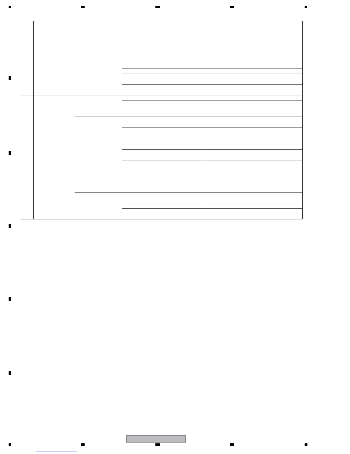
1. SPECIFCATIONS ............................................................................................................................................. 5
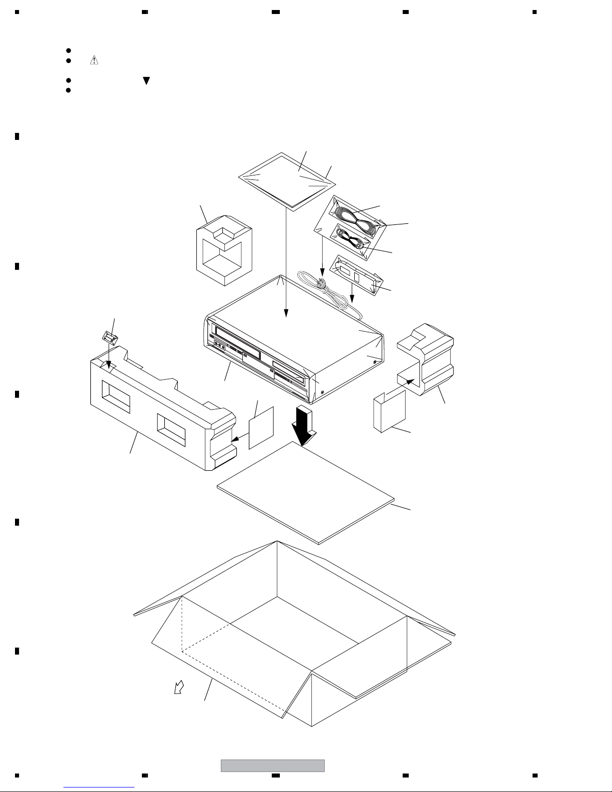
2. EXPLODED VIEWS AND PARTS LIST ............................................................................................................ 8
2.1 PACKING ................................................................................................................................................... 8
2.2 EXTERIOR SECTION.............................................................................................................................. 10
2.3 DECK ASSY (TOP SECTION)................................................................................................................. 12
2.4 DECK ASSY (BOTTOM SECTION) ......................................................................................................... 14
2.5 DVD MECHA ASSY ................................................................................................................................. 16
2.6 WIRING CABLE ....................................................................................................................................... 18
3. BLOCK DIAGRAM AND SCHEMATIC DIAGRAM..........................................................................................19
3.1 BLOCK DIAGRAM ................................................................................................................................... 19
3.1.1 DVD BLOCK DIAGRAM .................................................................................................................... 19
3.1.2 Y/C AUDIO / CCD / HEAD AMP BLOCK DIAGRAM......................................................................... 20
3.1.3 SYSTEM CONTROL BLOCK DIAGRAM........................................................................................... 21
3.1.4 REGULATOR BLOCK DIAGRAM ...................................................................................................... 22
3.1.5 OPERATION / DISPLAY BLOCK DIAGRAM ..................................................................................... 23
3.1.6 HiFi / DEMODULATOR BLOCK DIAGRAM ....................................................................................... 24
3.1.7 TUNER / JACK BLOCK DIAGRAM.................................................................................................... 25
3.2 SW,LOADING MOTOR PCB ASSYS and OVERALL WIRING DIAGRAM............................................... 26
3.3 DVD PCB ASSY(1/4) ............................................................................................................................... 28
3.4 DVD PCB ASSY(2/4) ............................................................................................................................... 30
3.5 DVD PCB ASSY(3/4) ............................................................................................................................... 32
3.6 DVD PCB ASSY(4/4) ............................................................................................................................... 34
3.7 VCR PCB ASSY(1/6) ............................................................................................................................... 36
3.8 VCR PCB ASSY(2/6) ............................................................................................................................... 38
3.9 VCR PCB ASSY(3/6) ............................................................................................................................... 40
3.10 VCR PCB ASSY(4/6) ............................................................................................................................. 42
3.11 VCR PCB ASSY(5/6) ............................................................................................................................. 44
3.12 VCR PCB ASSY(6/6) ............................................................................................................................. 46
3.13 OPERATION PCB ASSY ....................................................................................................................... 48
3.14 WAVE FORMS ....................................................................................................................................... 49
4. PCB CONNECTION DIAGRAM ..................................................................................................................... 53
4.1 DVD PCB ASSY....................................................................................................................................... 54
4.2 VCR PCB ASSY....................................................................................................................................... 58
4.3 OPERATION PCB ASSY ......................................................................................................................... 62
4.4 LOADING and SW PCB ASSYS.............................................................................................................. 63
5. PCB PARTS LIST ........................................................................................................................................... 64
6. ADJUSTMENT ............................................................................................................................................... 73
6.1 SERVICING FIXTURES AND TOOLS ..................................................................................................... 73
6.2 ADJUSTMENT ITEMS AND NECESSARY ADJUSTMENT POINTS...................................................... 74
6.3 SERVICE MODE LIST ............................................................................................................................. 76
6.4 CONFIRMATION OF HOURS USED....................................................................................................... 77
6.5 PREVENTIVE CHECKS AND SERVICE INTERVALS............................................................................. 78
6.6 MECHANICAL ADJUSTMENTS.............................................................................................................. 79
6.7 ELECTRICAL ADJUSTMENTS ............................................................................................................... 83
6.8 WHEN REPLACING DVD DECK ............................................................................................................. 85
6.9 WHEN REPLACING EEPROM (MEMORY) IC ........................................................................................ 86
7. GENERAL INFORMATION ............................................................................................................................. 87
7.1 SYSTEM SWITCH MODE ....................................................................................................................... 87
7.2 TAPE REMOVAL METHOD AT NO POWER SUPPLY............................................................................. 88
7.3 DISC REMOVAL METHOD AT NO POWER SUPPLY ............................................................................. 88
7.4 PARENTAL CONTROL -RATING LEVEL................................................................................................. 89
7.5 DISASSEMBLY ........................................................................................................................................ 90
7.6 DVD DECK SECTION.............................................................................................................................. 98
7.7 KEY TO ABBREVIATIONS..................................................................................................................... 101
7.8 DISC/CONTENT FORMAT .................................................................................................................... 102
7.9 CLEANING............................................................................................................................................. 103
8. PANEL FACILITIES ...................................................................................................................................... 107
8.1 FRONT AND REAR SECTION .............................................................................................................. 107
8.2 DISPLAY ................................................................................................................................................ 108
8.3 REMOTE CONTROL ............................................................................................................................. 109

DV-PT100-S 5
5678
5678
C
D
F
A
B
E
1. SPECIFCATIONS
G-1 Outline of the product DVD VIDEO PLAYER & VHS Player / Recorder
G-2 DVD System Color System NTSC
Disc DVD, CD-DA, CD-R/RW
Disc Diameter 120 mm , 80 mm
Deck Disc Loading System Front Disc Loading
Motor 3 Motors
Pick up 1-Lens 2-Beams System
Playback time (Max) DVD 1-Layer 135min (4.7GB)
DVD 2-Layer 245min (8.5GB)
CD 74min
VIDEO CD --min
Search speed Fwd 4 steps
Actual 2-45 times (DVD)
4-40 times (CD)
Rev 4 steps
Actual 2-45 times (DVD)
4-40 times (CD)
Slow speed Fwd 1/7-1/2 times
Actual --
Rev --
Actual --
G-3 VCR System VHS Player / Recorder
System Video System NTSC
Hi-Fi STEREO Yes
NTSC PB(PAL60Hz) No
Deck DECK OVD-7
Loading System Front
Motor 3
Heads Video Head 4Head
FM Audio Head 2Head
Audio / Control Mono/Yes
Erase (Full Track Erase) Yes
Erase (Normal Audio Track Erase) No
Tape Rec PAL -
Speed NTSC SP/SLP
Play PAL -
NTSC SP/LP/SLP
Fast Forward / Rewind Time (Approx.) at 25oC FF:4'50"/REW:2'30"
with Cassette T-120
Forward/Reverse NTSC or PAL-M SP/LP/SLP = 3x,5x / 7x,9x / 9x,15x
Picture Search PAL or SECAM -
Frame Advance Yes
Slow Speed 1/10
G-4 Tuning Broadcasting System US System M
System Tuner and System 1Tuner
Receive CH Destination US (w/CATV)
Tuning System F-Synth
Input Impedance VHF/UHF 75 OHM
CH Coverage 2-69,4A,A-5~ A-1,A~I,
J~ W, W+1-W+84
Intermediate Picture (FP) 45.75 MHz
Frequency Sound (FS) 41.25 MHz
FP-FS 4.50 MHz
Preset CH -
RF Converter Output Yes
Channel 3 or 4 ch
Level / Impedance 66 dBu / 75 Ohm
Sound Selector No
Stereo / Dual TV Sound US-ST
Tuner Sound Muting Yes

DV-PT100-S
6
1234
1234
C
D
F
A
B
E
G-5 Power Power Source AC 120V 60Hz
DC -
Power Consumption 18 W at 120V 60Hz
Stand by 2 W at 120V 60Hz
Per Year -- W
Protector Power Fuse Yes
Safety Circuit Yes
IC Protector(Micro Fuse) No
G-6 Regulation Safety UL
Radiation FCC
Laser DHHS
G-7 Temperature Operation 5oC - 40oC
Storage -20oC - 60oC
G-8 Operating Humidity Less than 80% RH
G-9 Signal Video Signal Output Level 1 V p-p/75 ohm (DVD,VCR)
S/N Ratio (Weighted) 65 dB(DVD) 50 dB(VCR)
Horizontal Resolution 500 Lines (DVD) 230 Lines(VCR Mode)
RGB Signal Output Level -
Audio Signal Input Level Microphone -
Input Level Line -8 dBm/ 50k ohm (VCR, 0dBm=0.775Vrms)
Output Level Line
-8 dBm/ 1k ohm (VCR,
0dBm=0.775Vrms)
-12dBm/ 1k ohm (DVD, -20dBFs
0dBFs=2 0Vrms)
Digital Output Level 0.5 V p-p / 75 ohm(DVD)
S/N Ratio at (Weighted) 90dB(DVD), 42dB(VCR at SP)
Harmonic Distortion (1KHz) Typical 0.02% (1KHz) (DVD) , 1.5% (1KHz) (VCR)
Frequency Response : DVD Mode at DVD 4 Hz - 22 KHz
DVD Mode at VIDEO CD -
DVD Mode at CD 4 Hz - 20 KHz
VCR Mode at SP 100Hz - 10 KHz
VCR Mode at LP -
VCR Mode at SLP 100Hz - 4 KHz
Hi-Fi Audio Signal Dynamic Range : More than 90dB
Frequency Response 20Hz ~20kHz
Wow And Flutter : Less than 0.01 %Wrms
Channel Separation : More than 60 dB
Harmonic Distortion : Less than 0.01

DV-PT100-S 7
5678
5678
C
D
F
A
B
E
Accessories
• Remote control ×1
(076R0JN020) • RF antenna cable ×1
(06CPL02006)
• Audio / Video cable(L=1.2m) ×1
(red/white/yellow)
(06CPBA2003)
• Dry cell batteries ×2
(AAA/R03)
• Warranty Card
• Operating Instructions
Red
White
Yellow

DV-PT100-S
8
1234
1234
C
D
F
A
B
E
2. EXPLODED VIEWS AND PARTS LIST
2.1 PACKING
Parts marked by "NSP" are generally unavailable because they are not in our Master Spare Parts List.
The mark found on some component parts indicates the importance of the safety factor of the part.
Therefore, when replacing, be sure to use parts of identical designation.
Screws adjacent to mark on product are used for disassembly.
For the applying amount of lubricants or glue, follow the instructions in this manual.
(In the case of no amount instructions, apply as you think it appropriate.)
NOTES:
1
2
6, 8
10
5
13
12
14
11
3
2
4
9
7
15
FRONT

DV-PT100-S 9
5678
5678
C
D
F
A
B
E
PACKING parts List
Mark No. Description Part No.
1 Gift Sheet 791WHA0100
2Package,Back 792WHAA117
3Package,Front 792WHA0558
4 Gift Box 793WCDC541
5Pad,Flat 795WCA0674
6 Instruction Book Kit (English) J2E51401A
7Poly Bag (185x270xT0.04) Y817041000
8 Guarantee Card J2D30902A
9Pad Type : B 795WCAA224
10 Polybag,Instruction JB5UD200
11 Remote Control 076R0JN020
12 RF Antenna Cable 06CPL02006
13 Audio/Video Cable 06CPBA2003
NSP 14 Dry Cell Battery(AAA/R03) 1412004008
15 Pad Type : A 759WCAA223

1234
C
D
F
A
B
E
2.2 EXTERIOR SECTION
PCB130
(DVD PCB ASS'Y)
PCB010
(VCR PCB ASS'Y)
PCB270
(OPERATION PCB ASS'Y)
Refer to
"2.3 DECK ASSY (TOP SECTION)"
"2.4 DECK ASSY (BOTTOM SECTION)".
Refer to
"2.5 DVD MECHA ASSY"
6
5
1
50 50
50
50
19
13
17
12
10
20
8
9
16
(2/2)
16
(1/2)
46
42
50
3
43
53
7
20
Adhesive
Y113031000
C
B
A
47
27
27
28
26
47
47
40
49
35
49
54
54
34
52
48
22
37
41
14
2
30
33
31
29
33
47
39
55
51
55
44
51
24
25
32
53
32
53
47
11
11
36

DV-PT100-S 11
5678
5678
C
D
F
A
B
E
EXTERIOR SECTION parts List
Mark No. Description Part No.
1DVD PCB Assy (PCB130) A2E514X130
2 VCR MT PCB Assy(PCB010) A2E514X010
3
OPERATION PCB Assy(PCB270)
A2E514X270
4•• • •
5DVD MECHA Assy A2E504X650
6 DECK Assy A2E504X420K
7Front Cabi Assy 7A701A279A
8 Cabinet, Front 701WPJC889
9 Plate, Display 711WPDA591
10 Flap, VCR 712WPJC092
>
11 AC Cord & Bush (CD501) 1209614920
12 Glass, LED-DVD 713WPA0194
13 Glass, LED-VCR 713WPA0193
>
14 Fuse (F501 : 2.5A)51MS025L 081PC2R505
15 • • • •
16 Button, Frame_VCR 738WPBA107
17 Button, Frame_DVD 738WPBA108
18 • • • •
19 Spring, Flap 743WKA0042
20 Cushion, Leg 800WFAA015
21 Bottom Cabi Assy 7G7610007A
22 Plate, Bottom 702WSA0216
23 Angle, Center 761WSA0175
24 Plate Tray_Front 712WPBA076
25 Sheet DVD 7235630010
26 Angle Front 761WSAA025
27 Cushion 65TS10-10 8965TS1010
(10 x 20 x 25)
28 Holder, Disc 761WPA0296
29 Holder, Deck 701WPA0686
30 Holder, Deck 701WPA0751
31 Heat Sink IC A023 763WSAA023
32 Spring, Earth 753WUA0065
33 Holder, End Sensor 85OP700038
34 Sheet, Rating 722631A001
35 Sheet, Jack 7230007787
36 Sheet, Caution 726000A073
37 Shield, COMPO 752WSA0290
38 • • • •
39 Shield, 3Pin Jack 752WUAA001
40 Holder, DVD (BR) 761WPA0261
41 Holder, DVD (BL) 761WPA0321
42 Holder, Deck Top 761WPA0262
43 Cabinet, Top 702WSA0212
44 Fiber Washer (3 x 3.2 x T0.5) 800WF00004
45 • • • •
46 Screw (3x29) 8109130B9U
47 Screw (3x7) 810923070U
48 Screw (3x10) 8109I30A0U
49 Screw (3x8) 810923080U
50 Screw (3x6) 8109K3060U
51 Screw (3x33R) 8154D3033U
52 Screw (3x4) 810713040U
53 Screw (2.6x8) 811022680U
54 Screw (2.6x6) 810722660U
55 SEMS (screw 3x8) 810F13080U
Mark No. Description Part No.

DV-PT100-S
12
1234
1234
C
D
F
A
B
E
2.3 DECK ASSY (TOP SECTION)
NOTE: Applying positions AA, AB, AC, AD and AE for the
grease are displayed for this section.
Check if the correct grease is applied for each position.
Class Part No. Part Name Mark
Grease Y315061000 G-555G AA
Y315071000 MG-33 AB
Y31D011000 FG-84M AC
Y315041000 FL-721 AD
Y315141000 G-313Y AE
To VCR MT PCB Assy
CP102
CONTACT SIDE
NON-CONTACT
SIDE
34
35
42
48
48
29 37
47
5
4
8
23
18
52
52
22
20
19
11
10 26
27
38
24 46
2
3
32
1
9
39
50
51
31
30
36
49
40
41
51
51
16
17
13
14
21
15
7
6
12 33
53
28
25
AA
AA
AA
AA
AE
AE
AE
AE
AE
AE
AE
AB
AB
AB
AC
AE
AE
AA
AB
AB
AC
AD
AB
AB
AB
AB
AB
AB
AB
AB
AB
AB
AB
AE
AE

DV-PT100-S 13
5678
5678
C
D
F
A
B
E
DECK ASSY (TOP SECTION) parts List
Mark No. Description Part No.
1 Pinch Roller Block (VA) 85OA400240
2 AHC Assy 85OA500026
3Worm 85OP600581
4 Base, AC Head 85OP500083
5 Spring, AC Head 85OP800324
6 Main Chassis Assy 85OA000516
7Arm Idler Assy 85OA200090
8 Inclined Base T Unit 3S 85OA400223
9 P5 Arm Assy 2 85OA400232
10 Tension Arm Assy 2 85OA400235
11 Inclined Base S Unit 85OA400231
12 Spring, Locker 85OP800367
13 Cass, Holder 85OP900736
14 Cass, Side L 85OP900748
15 Cass, Side R 85OP900749
16 Locker, R 85OP900739
17 Link Unit 85OA900228
18 Post, Cass Guide 85OP000496
19 Reel, S (S) 85OP200316
20 Reel, T (S) 85OP200317
21 Gear, Idler 85OP200308
22 Holder, Tension 85OP400492
23 Cap. P4 85OP400520
24 Band, Tension 85OP400542
25 Connect, Tension 85OP400533
26 Arm, Brake T 85OP600573
27 Band, Brake T 85OP600584
28 Spring, Tension 85OP800322
29 Spring, Brake T 85OP800360
30 Lever, Link 85OP900743
31 Lever, Flap 85OP900744
32 Cass, Opener 85OP900745
33 Reflector, LED 85OP700035
34 Bracket, Top 3V 85OP900746
35 Cord Jumper (CD1501) 122H071704
36 Cord Jumper (CD1502) 122Y021902
37 Head (Audio Control)(H5001) 1523Q91004
38 Head (Full Erase)(H5002) 1543Q02014
>
39 Motor, Loading (M101) 1596S98001
40 Micro Motor (M2003) 1589S11020
>
41 Cylinder Unit Assy (UN4001) A2D312H500
42 Cord Jumper (CD102) 122T041508
43 • • • • •
44 • • • • •
45 • • • • •
46 Screw (2.6x8) 8107226804
47 Screw (2.6x4) 8107226404
48 Screw (M2x6) 8102120604
49 Screw (2.6x6) 8109126604
50 Screw/Washer (A) (M3x4) 810A130404
51 Screw/Washer (A) (M2.6x5) 810A126504
52 Polyslider Washer 82Q264713N
53 Screw (Bind 2.6x6) 8107226604
Mark No. Description Part No.

DV-PT100-S
14
1234
1234
C
D
F
A
B
E
2.4 DECK ASSY (BOTTOM SECTION)
NOTE: Applying positions AA, AB, AC, AD and AE for the
grease are displayed for this section.
Check if the correct grease is applied for each position.
Class Part No. Part Name Mark
Grease Y315061000 G-555G AA
Y315071000 MG-33 AB
Y31D011000 FG-84M AC
Y315041000 FL-721 AD
Y315141000 G-313Y AE
8
6
23
10
2
4
15
16
24
7
3
5
9
13
22
19
18
17
21
1
20
22
22
12 11
14
AA
AA
AA
AD
AA
AA
AA
AA
AA
AA
AB
AB
AB
AB
AB
AB
AB
AB
AB
AB
AA
AA
AA
AA
AA
AA
AA
AA

DV-PT100-S 15
5678
5678
C
D
F
A
B
E
DECK ASSY (BOTTOM SECTION) parts List
Mark No. Description Part No.
1 Belt, Capstan (S) 85OP200290
2 Main Chassis Assy 85OA000516
3 Clutch Assy 85OA200089
4 Loading Arm S Unit 85OA300065
5 Loading Arm T Unit 85OA300066
6 Gear, Clutch 85OP200311
7 Gear, Coupling 85OP200312
8Lever, Clutch 85OP200313
9 Gear, Main Loading 85OP300194
10 Lever, Tension 85OP400490
11 Cam, Pinch Roller 85OP600577
12 Cam, Main 85OP600578
13 Rod, Main 85OP600579
14 Gear, Joint 85OP600582
15 Spring, Coupling 85OP800355
16 Spring, Ring 85OP800356
17 Holder, Capstan 85OP400549
18 Cord Jumper (CD1501) 122H071704
19 Cord Jumper (CD1502) 122Y021902
>
20 Capstan DD Unit (M2001) 1510S98042
21 Screw (2.6x4) 8107226804
22 E-Ring (3.0) 83ETW30000
23 Screw (2.6x6) 8109126604
24 Polyslider Washer (CUT) 82P184505N

DV-PT100-S
16
1234
1234
C
D
F
A
B
E
2.5 DVD MECHA ASSY
Applying positions AA and AB for the grease
are displayed for this section.
Check if the correct grease is applied for each
position.
NOTE:
CLASS MARK
GREASE G-555G AA
SF-112 AB
PART NO.
Y315061000
PART NAME
Y315121000
AA
AA
AA
8
D
E
8
34
9
14 18
21
15
AA
AA AA
AA
23
20
11
4
3
7
28
6
1
AB
AA
AB
AA
12
PCB610
(LOADING MOTOR PCB ASS'Y)
29
31
CD2302
16
17
33
CD2001
32
10
2
22
30
13
24
5
19
Do not replace the parts. Because,
minute adjustments are needed if
this condition is disassembled
further more.
If the repair is needed, replace the
DVD MECHA ASS'Y.
PCB640
(SW PCB ASS'Y)
CD2301
Cannot supply separately.
If the repair is needed, replace the
LOADER SUB ASS'Y.

DV-PT100-S 17
5678
5678
C
D
F
A
B
E
DVD MECHA ASSY parts List
Mark No. Description Part No.
NSP 1 Loading Motor PCB Assy A2D801X610
2•• • •
3 Loading Motor Assy 1596S18002
4 Motor Pulley 92P100097A
5 FEED Motor 1515S98002
6 Cord Cable (24P)(CD2001) 122H0O1901
7 Cord Jumper (CD2302) 122H052601
8 Insulator (F) 92P200013A
9 Belt Loading 92P200012A
10 Insulator (R) 92P200014A
11 Frame main 92P100091A
12 Tray 92P100100A
13 Holder Traverse 92P100109A
14 Gear Pulley 92P100095A
15 Gear Main 92P100096A
16 Gear Middle 92P100108A
17 SW PCB Assy (PCB640) A2E220T640
18 Clamper Plate 92P000014A
19 Loader SUB Assy 92SBB0020A
20 Clamper 92P100094A
21 Screw (M1.7x3) 814011730U
22 Screw (M1.7x2.3) 814011723U
23 Rack Loading 92P100093A
24 Gear Motor 92P100088A
25 • • • •
26 • • • •
27 • • • •
28 Cord Jumper (CD2301) 122H062102
29 Switch (SW1) 0515S32002
30 Push Switch (SW2) 0500101037
31 Screw (2.6x8) 811022680U
32 Screw (2x8) 816112080U
33 Screw (Bind 2x8) 811022080U
34 DVD MECHA ASSY A2E504X650

DV-PT100-S
18
1234
1234
C
D
F
A
B
E
2.6 WIRING CABLE
B
C
A
* All cables are ASSY parts.
VCR PCB
CD501
OPERATION PCB
DVD PCB
DVD DECK
CD2301
CD2001
CP2601
CP2603
CP2602
CP8101
CD4002
V651
J8003
J8004
J8005
OS651
TU301
OS8001
J8007
J8006
J8008
J8001
CP8001
S501
S502
CP651
CP501
TP101 TP701
TP3001TP3002
CP103
FE HEAD
CP102
AC HEAD
CD102
AC IN
CD681
CP681
CD8001
CD501
CD2302

DV-PT100-S 19
5678
5678
C
D
F
A
B
E
3. BLOCK DIAGRAM AND SCHEMATIC DIAGRAM
3.1 BLOCK DIAGRAM
3.1.1 DVD BLOCK DIAGRAM
CP8101_2
IMSA-9604S-14F
1
10
11
12
13
14
2
3
4
5
6
7
8
9
CD4002
CU2B2201
1
10
11
2
3
4
5
6
7
8
9
SDD0~SDD15
SDA0~SDA11
HA0~HA20
HD0~H120
FROM/TO
TUNER/JACK
FROM/TO POWER
DAC A,B,C,D
GND
U(B)
GND
V(R)
GND
AUDIO-L
GND
AUDIO-R
ZERO
DVD RESET
Y(G)
V SW
DVD-H
CVBS
RX
TX
GND(M)
P.CON+9V
UNREG+3.8V
UNREG+3.8V
P.CON+A5V
GND(A)
GND(D)
GND(D)
SPDIF
PCM1753DBQR
ZR36762PQCG_V
REG+3.3V/+1.9V
DVD AUDIO L
DVD AUDIO R
22 I CLKI DAT
S-24C04BFJ-TB
3.3V
1.9V
TR+/-,FO+/-
SPDL+/-,SLED+/-
S MUTE
ADC IN 5,6,7
TRACK,FOCUS_PWM
SPINDLE,SLED_PWM
SPDL_SENS
Loading Moter
Spindle Moter
Sled Moter
Pick up
DEFECT,LINK,MIRR,LDON
IC2601
READ CHANNEL
ZR36708TQC
Moter Driver
IC2301
LA6565
CD,DVD,LD
RF
A,B,C,D,E,F
HOME,TIN SW ,TOUT SW
RFA_SDEN,DATA,SCLK
AAF_CE,FE,TE,PI
FNN,FNP
VBIASS0,S1
STEREO DAC
IC8502
ALRCLK
ABCLK
AMCLK
ASDATA0
IC4002
EEPROM
SI-3007KWM-TL
IC4003
DM3
SDRAM 64M
IC4005
HY57V161610ETP-7
IC4007
FLASH 8M
SST39VF800A-70-4C-EK-D
MPEG Decoder
W/Video Encorder
W/u-CON
W/DSP
IC4001
(Vaddis6V)
DVD LOADER

DV-PT100-S
20
1234
1234
C
D
F
A
B
E
3.1.2 Y/C AUDIO / CCD / HEAD AMP BLOCK DIAGRAM
AUDIO SIGNAL (PB)
AUDIO SIGNAL(REC)
RECORD LUMINANCE SIGNAL
PLAYBACK LUMINANCE SIGNAL
RECORD COLOR SIGNAL
TUNER VIDEO SIGNAL
PLAYBACK COLOR SIGNAL
PLAYBACK VIDEO SIGNAL
30
2
22
32
10
21
67
65
7
9
36
6
8
34
55
54
53
57
43
578 76
H.AMP
SW
REC AMP
CP102_1
4
3
2
AUDIO PB
AUDIO REC
CTL+
HEAD
AUDIO
CONTROL
1CTL-
CTL+
CTL-
Y/C/AUDIO/CCD/HEAD AMP IC
IC101
LA71206M 39
Q107
BUFFER
TIMMING CCD
OUT
DRIVER CLAMP
37
58
60
59
24
25
66
H.SW
72
73
74 H.SW
H
L
H
L
H
L
PB.EE
P
R
WC
DC
NL
EMPHA
REC
FM-EQ FM
MOD
PR
AGC
AMP
KIL
FM
AGC
DELAY
PB
FM-EQ
PB
PHASE-EQ
P
R
C-LPF
GCA B-UP
AMP
ACC
AMP
Main
CONV
3.58M
BPF2
AUTO BIAS
P
R
KIL
B.D. PB
AMP
3.58M
BPF1
DOUBLE
LIM
FM
DEM SUB
LPF
V/I
CONV P
R
Y-LPF
YNR/
COMB
N.L.
DEEM
NC1
Y/C MIX
SYNC
SEP
VCA
CLAMP
1/2
FBC
Chara
INS.
6dB
PR
P
R
V-AGC
L101
CLAMP
EQ
AMP
LINE
AMP
MUTE
ALC
Y/C_CS
Y/C_DATA
Y/C_CLK
H. AMP_SW
C. ROTARY
H. SW
ENV. DET
COMP
DUMMY_V. SYNC
C.SYNC
FRONT_V_IN
TUNER_V
TO_NORMAL_A
FROM_NORMAL_A
6
2
3
1
5
Q105
BIAS CTL
11
4
P. CON + 5V
H.AMP SW/
AUDIO
MUTE
C ROT
RF SW IN
ENV DET
CONP
OUT
Q104
BIAS OSC
Q103
SW
Q101, Q102
AUDIO PB SW
HF1
HF2
HI-FI/DEMODU
LATOR
HF_COM
COIL, BIAS OSC
X101
3.578545M Hz
VX01
50 49
PULL
41
Q109
BUFFER
TUNER/JACK
SYSCON
HI-FI/DEMODU
LATOR
80
SERIAL
DECODER
AUDIO_MUTE-H
V.REC_ST-H
LPF
ALC
DET
PR
SYSCON
SYSCON
EP/LP-CH1 (R)
EP/LP-CH2 (L)
CP101
6
5
4
SP-CH1 (R)
SP_COM
SP-CH2 (L)
CYL
3
2
1
EP/LP_COM
HF2 (L)
HF_COM
HF1 (R)
7
8
9
FE HEAD (HOT)
FE HEAD (GND)
FE HEAD
2
1
CP103
DETAL
ENH
28
DVD V OUT
FSC
26
Y/C_VIDEO_OUT
POWER
43
4FSC
FSC
Table of contents
Other Pioneer DVD VCR Combo manuals