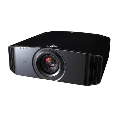
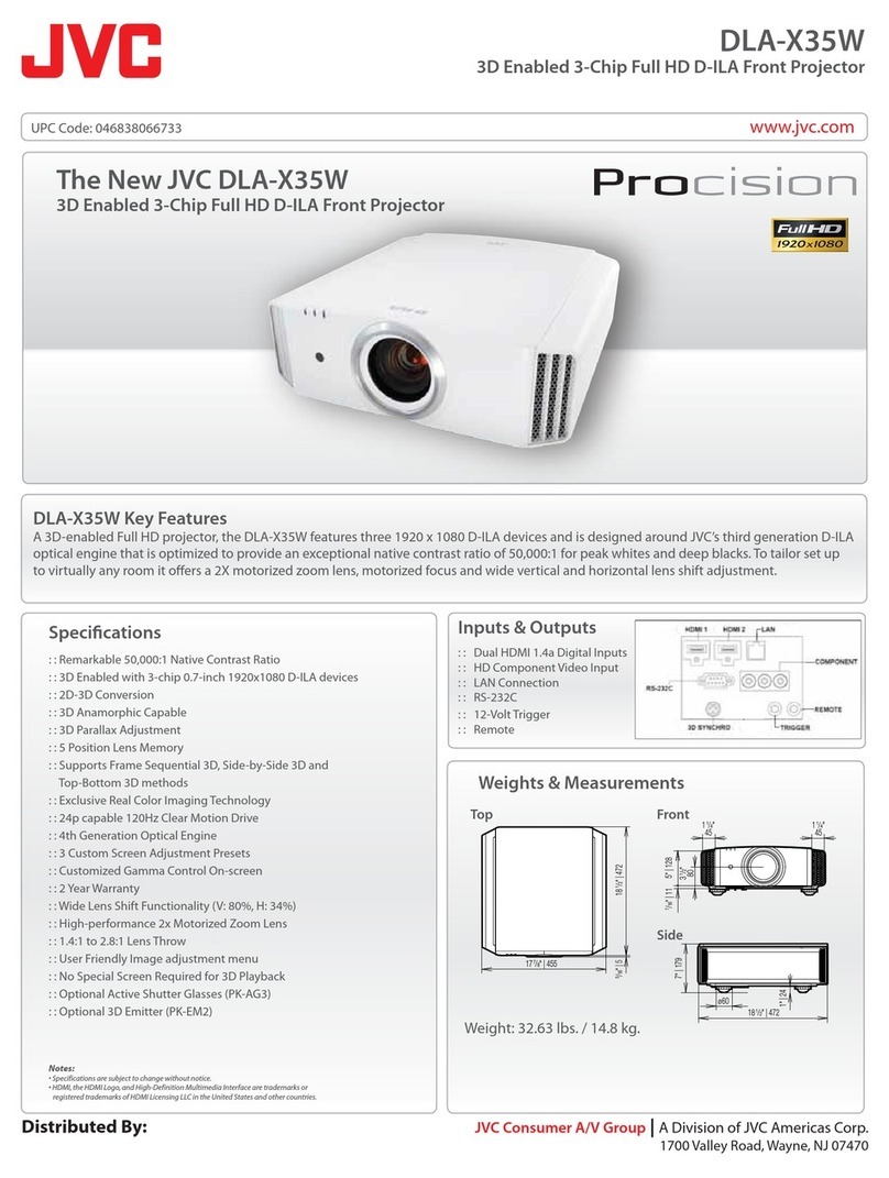
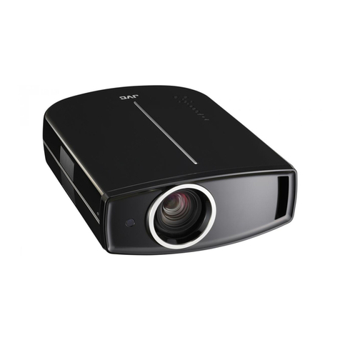
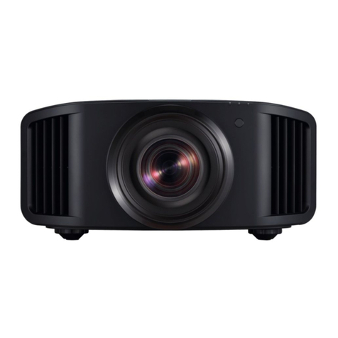
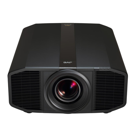
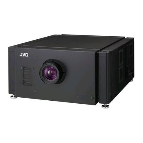
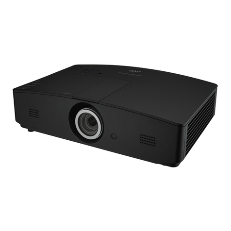
JVC DLA-G150CLU User manual

DLA-G150CLU
DLA-G150CLE
DLA-G150CLU
OPERATING INSTRUCTIONS
Mar. 2002 No. 51931
[ DLA-G150CLU / DLA-G150CLE ]
DVI
VIDEO
COMP
Y/C
RM-M160 REMOTE CONTROL UNIT
QUICK
ALIGN.
PC1 PC2 Y/C
HIDE
PRESET
ENTEREXIT
MENU
FREEZE
SCREEN
OPERATE
DIGITAL
ZOOM
ZOOM FOCUS
W
W
S
T
W
T
SCREEN
KEYSTONE
W
S
PROJECTOR
MANUEL D’INSTRUCTIONS : PROJECTEUR
DLA-G1 0CLU
INSTRUCTIONS
®
DLA-G150CLU
(Le ses are optio al) LCT1123-001B
DLA-G150CLE

DLA-G150CLU
DLA-G150CLE
1-2 No.51931
3
ENGLISHFRANÇAIS
– This product should be operated o ly with the type of
power source i dicated o the label. If you are ot sure
of the type of power supply to your home, co sult your
product dealer or local power compa y.
– This product is equipped with a three-wire plug. This
plug will fit o ly i to a grou ded power outlet. If you are
u able to i sert the plug i to the outlet, co tact your
electricia to i stall the proper outlet. Do ot defeat the
safety purpose of the grou ded plug.
– Power-supply cords should be routed so that they are ot
likely to be walked o or pi ched by items placed upo or
agai st them. Pay particular atte tio to cords at doors,
plugs, receptacles, a d the poi t where they exit from the
product.
– For added protectio of this product duri g a light i g
storm, or whe it is left u atte ded a d u used for lo g
periods of time, u plug it from the wall outlet a d
disco ect the cable system. This will preve t damage
to the product due to light i g a d power li e surges.
– Do ot overload wall outlets, exte sio cords, or
co ve ie ce receptacles o other equipme t as this ca
result i a risk of fire or electric shock.
– Never push objects of a y ki d i to this product through
ope i gs as they may touch da gerous voltage poi ts or
short out parts that could result i a fire or electric shock.
Never spill liquid of a y ki d o the product.
– Do ot attempt to service this product yourself as
ope i g or removi g covers may expose you to
da gerous voltages a d other hazards. Refer all service
to qualified service perso el.
– U plug this product from the wall outlet a d refer service
to qualified service perso el u der the followi g
co ditio s:
a) Whe the power supply cord or plug is damaged.
b) If liquid has bee spilled, or objects have falle o the
product.
c) If the product has bee exposed to rai or water.
d) If the product does ot operate ormally by followi g
the operati g i structio s. Adjust o ly those co trols
that are covered by the Operatio Ma ual, as a
improper adjustme t of co trols may result i damage
a d will ofte require exte sive work by a qualified
tech icia to restore the product to ormal operatio .
e) If the product has bee dropped or damaged i a y
way.
f ) Whe the product exhibits a disti ct cha ge i
performa ce – this i dicates a eed for service.
– Whe replaceme t parts are required, be sure the
service tech icia has used replaceme t parts specified
by the ma ufacturer or with same characteristics as the
origi al part. U authorized substitutio s may result i
fire, electric shock, or other hazards.
– Upo completio of a y service or repairs to this product,
ask the service tech icia to perform safety checks to
determi e that the product is i proper operati g
co ditio .
– The product should be placed more tha o e foot away
from heat sources such as radiators, heat registers,
stoves, a d other products (i cludi g amplifiers) that
produce heat.
– Whe co ecti g other products such as VCR’s, a d
perso al computers, you should tur off the power of this
product for protectio agai st electric shock.
– Do ot place combustibles behi d the cooli g fa . For
example, cloth, paper, matches, aerosol ca s or gas
lighters that prese t special hazards whe over heated.
– Do ot look i to the projectio le s while the illumi atio
lamp is tur ed o . Exposure of your eyes to the stro g
light ca result i impaired eyesight.
– Do ot look i to the i side of this u it through ve ts
(ve tilatio holes), etc. Do ot look at the illumi atio
lamp directly by ope i g the cabi et while the
illumi atio lamp is tur ed o . The illumi atio lamp also
co tai s ultraviolet rays a d the light is so powerful that
your eyesight ca be impaired.
– Do ot drop, hit, or damage the light-source lamp (lamp
u it) i a y way. It may cause the light-source lamp to
break a d lead to i juries. Do ot use a damaged light-
source lamp. If the light-source lamp is broke , ask your
dealer to repair it. Fragme ts from a broke light-source
lamp may cause i jures.
– Xe o gas is e closed with high pressure i side the light-
source lamp (lamp u it) of this projector. If you drop or
impart a shock to the lamp, or discard it as is, there is the
possibility of explosio , leadi g to perso al i jury. Use
special care whe ha dli g the lamp. For a y u clear
poi ts, co sult your product dealer.
– Do ot “ceili g-mou t” the projector to a place which
te ds to vibrate; otherwise, the attachi g fixture of the
projector could be broke by the vibratio , possibly
causi g it to fall or overtur , which could lead to perso al
i jury.
– Use o ly the accessory cord desig ed for this product to
preve t shock.
The power supply voltage rati g of this product is
AC 120 V, the power cord attached co forms to the
followi g power supply voltage. Use o ly the power cord
desig ated by our dealer to e sure Safety a d EMC.
Whe it is used by other power supply voltage, power
cable must be cha ged.
E sure that the power cable used for the projector is the
correct type for the AC outlet i your cou try.
Co sult your product dealer.
*DO NOT allow any unqualified person to
install the unit.
Be sure to ask your dealer to i stall the u it (eg.
attachi g it to the ceilli g) si ce special tech ical
k owledge a d skills are required for i stallatio .
If i stallatio is performed by a u qualified perso , it
may cause perso al i jury or electrical shock.
Power cord
Power supply voltage: AC 120 V
2
SAFETY PRECAUTIONS
IMPORTANT INFORMATION
About burning-in of the D-ILA device
Do ot allow the same still picture to be projected for a lo g
time or a ab ormally bright video picture to be projected.
Do ot project video images with high-i te sity or high-
co trast o a scree . The video image could be bur ed i to
the D-ILA device.
Use special care whe projecti g video games or computer
program images. There is o problem with ordi ary
video-cassette playback images.
About the installation place
Do ot i stall the projector i a place that ca ot support its
weight securely.
If the i stallatio place is ot sturdy e ough, the projector
could fall or overtur , possibly causi g perso al i jury.
IMPORTANT SAFEGUARDS
Electrical e ergy ca perform ma y useful fu ctio s. This
u it has bee e gi eered a d ma ufactured to assure your
perso al safety. But IMPROPER USE CAN RESULT IN
POTENTIAL ELECTRICAL SHOCK OR FIRE HAZARD. I
order ot to defeat the safeguards i corporated i to this
product, observe the followi g basic rules for its i stallatio ,
use a d service. Please read these “Importa t Safeguards”
carefully before use.
– All the safety a d operati g i structio s should be read
before the product is operated.
– The safety a d operati g i structio s should be retai ed
for future refere ce.
– All war i gs o the product a d i the operati g
i structio s should be adhered to.
– All operati g i structio s should be followed.
– Place the projector ear a wall outlet where the plug ca
be easily u plugged.
– U plug this product from the wall outlet before clea i g.
Do ot use liquid clea ers or aerosol clea ers. Use a
damp cloth for clea i g.
– Do ot use attachme ts ot recomme ded by the
product ma ufacturer as they may be hazardous.
– Do ot use this product ear water. Do ot use
immediately after movi g from a low temperature to high
temperature, as this causes co de satio , which may
result i fire, electric shock, or other hazards.
– Do ot place this product o a u stable cart, sta d, or
table. The product may fall, causi g serious i jury to a
child or adult, a d serious damage to the product. The
product should be mou ted accordi g to the
ma ufacturer’s i structio s, a d should use a mou t
recomme ded by the ma ufacturer.
– Whe the product is used o a cart, care
should be take to avoid quick stops,
excessive force, a d u eve surfaces
which may cause the product a d cart to
overtur , damagi g equipme t or
causi g possible i jury to the operator.
– Slots a d ope i gs i the cabi et are provided for
ve tilatio . These e sure reliable operatio of the
product a d protect it from overheati g. These ope i gs
must ot be blocked or covered. (The ope i gs should
ever be blocked by placi g the product o bed, sofa,
rug, or similar surface. It should ot be placed i a built-i
i stallatio such as a bookcase or rack u less proper
ve tilatio is provided a d the ma ufacturer’s
i structio s have bee adhered to.)
For proper ve tilatio , separate the product from other
equipme t, which may preve t ve tilatio a d keep /
dista ce more tha 23-
5
/
8
" (60 cm).
WARNING :
TO PREVENT FIRE OR SHOCK HAZARDS, DO
NOT EXPOSE THIS APPLIANCE TO RAIN OR
MOISTURE.
CAUTION :
To reduce the risk of electric shock, do ot remove
cover.
Refer servici g to qualified service perso el.
This projector is equipped with a 3-blade grou di g-type
plug to satisfy FCC rule. If you are u able to i sert the
plug i to the outlet, co tact your electricia .
FCC INFORMATION (U.S.A. ONLY)
CAUTION :
Cha ges or modificatio ot approved by JVC could void
the user’s authority to operate the equipme t.
NOTE :
This equipme t has bee tested a d fou d to comply
with the limits for a Class B digital devices, pursua t to
Part 15 of the FCC Rules. These limits are desig ed to
provide reaso able protectio agai st harmful
i terfere ce i a reside tial i stallatio . This equipme t
ge erates, uses, a d ca radiate radio freque cy e ergy
a d, if ot i stalled a d used i accorda ce with the
i structio s, may cause harmful i terfere ce to radio
commu icatio s. However, there is o guara tee that
i terfere ce will ot occur i a particular i stallatio . If
this equipme t does cause harmful i terfere ce to radio
or televisio receptio , which ca be determi ed by
tur i g the equipme t off a d o , the user is e courage
to try to correct the i terfere ce by o e or more of the
followi g measures:
– Reorie t or relocate the receivi g a te a.
– I crease the separatio betwee the equipme t a d
receiver.
– Co ect the equipme t i to a outlet o a circuit
differe t from that to which the receiver is co ected.
– Co sult the dealer or a experie ced radio/TV
tech icia for help.
DLA-G150CLU
DLA-G150CLE
1-3
No.51931
ENGLISHDEUTSHFRANÇAISITALIANOESPAÑOL
Accessories
The following accessories are included with this projector. Check for them; if any item is missing, please
contact your dealer.
■
■■
■Remote control unit (RM-M160G)
■
■■
■AA/R6-size dry cell battery (×
××
×2)
(for checking operation)
■
■■
■Power cord
[approx. 8.2 ft (approx. 2. m)]
■
■■
■Ferrite core (×
××
×2)
■
■■
■Personal computer connection cable
[approx. 6. 6 ft (approx. 2 m)]
(D sub, 3 row 15 pin)
■
■■
■Video cable
[approx. 6. 6 ft (approx. 2 m)]
■
■■
■Conversion adapter for Mac
(for Macintosh)
■
■■
■BNC-RCA Conversion plug
■
■■
■ Hex. wrench
4
Contents
SAFETY PRECAUTIONS................. 2
Contents........................................... 4
Accessories .....................................
Controls and Features .................... 6
Fro t Side / Top Surface / Right Side .....................6
Left-ha d Side / Rear Side......................................7
Bottom Surface .......................................................8
Co trol Pa el o the Projector................................9
Co ector Pa el ...................................................11
Remote Co trol U it..............................................12
I stalli g Batteries.................................................14
Precautio s for usi g batteries..............................14
Installing the Projector.................. 1
Precautio s for I stallatio ....................................15
Adjusti g the I cli atio of the Projector...............16
I stalli g the Projector agai st the Scree ............17
Projectio Dista ce a d Scree Size....................18
Setti g the Amou t of Le s Shifti g......................19
Effective Ra ge a d Dista ce of the
Remote Co trol U it..............................................20
Setti g the Positio Selecti g Screw for Ceili g
Mou ti g ...............................................................21
Whe i stalli g (adjusti g/setti g) the u it............21
Connecting to Various Devices.... 22
Sig als that Ca Be I put to the Projector............22
Co ecti g to Video Devices................................24
Co ecti g to Hi-Visio Devices/DVD Players .....25
Co ecti g to Other Devices................................26
Co ecti g to Devices which Co trol the
Projector................................................................27
Co ecti g to Computer Devices .........................28
Co ecti g to DVI.................................................29
How to attach the ferrite core................................29
Co ecti g the Power Cord..................................30
Removi g the Le s Cap........................................30
Basic Operations........................... 31
1. Tur i g o the Power........................................32
2. Select the I put source to be Projected............33
3. Adjust the Scree Size (Zoomi g) ....................34
4. Adjust Focus .....................................................34
5. Setti g the Scree Aspect Ratio.......................34
Tur i g off Image (HIDE)......................................35
Removi g the Trapezoidal Distortio of the
Image....................................................................35
Quick Alig me t Fu ctio (QUICK ALIGN.)..........36
Displayi g a Still Picture (FREEZE)......................37
Zoomi g a Part of the Image
(DIGITAL ZOOM T/W) ..........................................37
Menu Operations........................... 38
Basic Me u Operatio ...........................................43
Cha gi g the Color System
(Video Me u Mode O ly)......................................45
Cha gi g the La guage Display...........................46
Cha gi g the Scree aspect ratio/HDTV format
(Video Me u Mode O ly)......................................46
Adjusti g Tracki g/Phase .....................................47
Setti g for Watchi g Image Software
(Video Me u Mode O ly) ..................................... 48
Adjusti g Picture Quality...................................... 49
Adjusti g Color temperature................................. 50
Adjusti g the Video Scree /Me u Positio .......... 51
Cha gi g the Image Gamma/Aspect Ratio
(Video Me u Mode O ly) ..................................... 52
Cha gi g the Image Size - Resize Fu ctio
(PC Me u Mode O ly).......................................... 53
Cha gi g the Clamp pulse positio
(PC Me u Mode O ly).......................................... 53
Setti g a d Adjusti g Other Fu ctio s
(OPTIONS)........................................................... 54
Getti g I formatio ............................................... 56
Replacing the Fuse........................ 7
Replacing the Light-Source
Lamp ............................................... 8
Cleaning and Replacing the
Filter Cover.....................................63
Troubleshooting.............................64
Warning Indication.........................66
Warning Messages ........................67
Specifications.................................70
Outside dime sio s.............................................. 72
Pi assig me t (Specificatio s for termi als) ...... 73
RS-232C external control..............74
Appendix.........................................76
DLA-G150CLU

DLA-G150CLU
DLA-G150CLE
1-4 No.51931
7
Co trols a d Features
ENGLISHDEUTSHFRANÇAISITALIANOESPAÑOL
Left-hand Side / Rear Side
pConnector panel
For details, refer to “Co ector Pa el” o page 11.
qRear adjustable foot (for leveling the projector)
It is set at the shortest positio whe shipped from the
factory. Tur the foot to make the projector level.
Adjustme t ca be made i the ra ge of +1.5° a d –1.5°
from the horizo tal positio . For details, refer to
“Adjusti g the I cli atio of the Projector” o page 16.
wAir inlet
This is the air i let. Do ot cover or obstruct this slot.
eControl panel
For details, refer to “Co trol Pa el o the Projector” o
page 9.
rLens shift knob cap
Whe you have mou ted a le s that uses the le s shift
fu ctio , ope this cap a d rotate the le s shift k ob to
move the le s positio . For more i formatio , refer to
“Setti g the Amou t of Le s Shifti g” o page 19.
VIDEO
PC
LAMPTEMPSTAND BY
MENU
KEYSTONE
PRESET
EXITENTER
OPERATE
HIDE
DOWN
UP
6
Controls and Features
Front Side / Top Surface / Right Side
1Exhaust vents
Ve ts for cooli g fa s through which warm air comes out.
CAUTION
• Do ot block the exhaust ve ts, or heat will build up i side,
possibly causi g a fire. Also, do ot touch the ve ts, or this
could give you a low-temperature bur .
2Carrying handle
Raise this ha dle whe carryi g the projector.
CAUTIONS
• Whe carryi g the projector, do ot tra smit shocks to it.
Also be careful to keep it bala ced.
• Do ot carry it while the light-source lamp is o or the
cooli g fa is operati g. This could cause perso al i jury.
3AC IN (power input) terminal
This is the power i put termi al where the supplied
power cord is co ected. For details, refer to page 30.
4Fuse holder
A fuse rated 12A/250V is i stalled. (Power source
protectio )
To replace the fuse, refer to page 57.
CAUTION
• Whe replaci g the fuse, use the same rati g a d type.
Otherwise, a fire may occur a d/or the projector may be
damaged.
5MAIN POWER switch
This is the mai power switch. Whe it is tur ed o , the
projector goes i to sta d-by state, a d the STAND BY
i dicator o the co trol pa el comes o . (Refer to
page 32.)
ON [ | ]: The mai power tur s o .
OFF [‡
‡‡
‡]: The mai power tur s off.
6Adjustable feet (for adjusting the height and
angle)
By exte di g the feet, the projector a gle ca be
adjusted up to +7°.
For details, refer to “Adjusti g the I cli atio of the
Projector” o page 16.
7Lens
O e of the optio al le s u its should be i stalled before
usi g the projector.
A le s-hole bli d cover (black o e) is i stalled whe the
projector is shipped from the factory.
For details o the types of optio al le ses available, refer
to page 18.
CAUTION
• Please co sult your authorized dealer or service ce ter for
i formatio about attachi g a optio al le s.
8Lens cap
This is the le s cap provided for the optio al le s.
Whe you are ot usi g the projector, attach the le s cap
to protect the le s from dirt or bei g damaged. (Refer to
page 30.)
9Remote sensor
Whe operati g with the remote co trol, aim it toward
this se sor. (Refer to page 20.)
LAMPTEMP
HIDE
PC
VIDEO
MENU
KEYSTONE
PRESET
EXITENTER
OPERATE
DOWN
UP
9
7
5432
8
6
1

DLA-G150CLU
DLA-G150CLE
1-5
No.51931
9
Co trols a d Features
ENGLISHDEUTSHFRANÇAISITALIANOESPAÑOL
Control Panel on the Projector
1STAND BY Indicator
ON : Whe i sta d-by mode.
Blinking :Whe i cool-dow mode.
Memo
About the cool-down mode:
This projector has a fu ctio to cool dow the heated lamp for a
fixed period of time (approx. 120 seco ds) after projectio is
fi ished. This feature is referred to as the cool-dow mode.
The purpose of the cool-dow mode is to preve t i er parts
from bei g deformed or broke by heat from the heated lamp
as well as to prolo g the life of the lamp.
CAUTIONS
• Do ot tur off the MAIN POWER switch while i the cool-
dow mode.
• Do ot place the projector o its side or sta d it upright
while i the cool-dow mode; this may block the ve ts.
2OPERATE indicator
ON : Whe the projector is i operatio (projecti g).
OFF : Whe the projector is ot i operatio ( ot
projecti g).
3OPERATE button
Whe the projector is i the sta d-by mode, press this
butto o e seco d or more, a d the projector is tur ed
o , causi g the OPERATE i dicator to light.
Press it o e seco d or more agai , a d the projector
goes i to the cool-dow mode, the sta d-by mode.
(Refer to page 32.)
* You ca ot use the OPERATE butto for about o e
mi ute after the lamp bli ks. Press the butto after a
mi ute or lo ger has elapsed.
Memo
While in the cool-down mode (STAND BY indicator is blinking):
Eve if you press the OPERATE butto , the projector is ot
tur ed o . Wait u til the projector e ters sta d-by mode
(STAND BY i dicator stays lit).
4PC button
Use this butto to select a device co ected to the PC 1,
PC 2 or DVI termi als. Each time you press the butto ,
the selectio alter ates amo g PC 1, PC 2 a d DVI.
* “PC1” , “PC2” or “DVI” will be displayed o the top right of
the projected image. (This fu ctio ca be disabled by
the me u.)
5VIDEO button
Use this butto to select a device such as a video deck
co ected to the AV IN (Y/C, VIDEO or COMP) termi al
of the projector. Each time you press the butto , the
selectio alter ates amo g Y/C, VIDEO a d COMP.
* “Y/C”, “VIDEO” or “COMP” will be displayed o the top right of
the projected image. (This fu ctio ca be disabled by the
me u.)
6MENU button
Use this butto to e ter or exit the me u mode. The mai
me u appears or disappears at the scree . For details,
refer to “Basic Me u Operatio ” o page 43.
7ENTER button
This butto will be used i the me u mode. Use to
display the hierarchical me us. Also use whe “ENTER”
is displayed agai st the item o the me u scree or
whe the “All reset” selectio is co firmed. For details,
refer to “Basic Me u Operatio ” o page 43.
8Cursor buttons
5
/
∞
/
2
/
3
These butto s will be used i the me u mode to select a
item, or to set or adjust the value. For details, refer to
“Basic Me u Operatio ” o page 43.
VIDEO
PC
LAMPTEMPSTAND BY
MENU
KEYSTONE
PRESET
EXITENTER
OPERATE
HIDE
DOWN
UP
3
4
5
6
7
2
1
r
w
q
p
9
8
e
LAMP TEMP STAND BY
HIDE
PC
VIDEO
MENU
KEYSTONE
PRESET
EXIT ENTER
OPERATE
8
Co trols a d Features
Bottom Surface
tAir inlet (filter)
Air is take i through the filter to cool the light-source
lamp. If the filter is blocked or if somethi g that obstructs
the flow of air is placed arou d the projector, heat may
build up i side a d could cause a fire. For required
space, refer to “Precautio s for I stallatio ” o page 15.
CAUTIONS
• Be careful as paper, cloth or soft cushio could be draw i
if placed earby. Do ot block the filter, or heat may build
up a d could cause a fire.
• Clea the filter periodically. For details, refer to “Clea i g
a d Replaci g the Filter Cover” o page 63. Depositio of
dirt o the filter reduces the cooli g effect, causi g heat to
build up i side, which could cause a fire or malfu ctio .
yOpening for replacing the light-source lamp
For replaci g the light-source lamp, refer to “Replaci g
the Light-Source Lamp” o page 58.
uFixing foot
iPosition selecting screw for ceiling mounting
Whe usi g the projector i a upside-dow , ceili g-
mou ted positio (i verted top-to-bottom a d right-to-
left), the “positio selecti g screw for ceili g mou ti g”
must be tur ed to switch to ceili g mou ti g.
This will correct varia ce i color images (shadi g),
which otherwise would occur i ceili g mou ti g.
For more i formatio , refer to “Setti g the Positio
Selecti g Screw for Ceili g Mou ti g” o page 21.
CAUTION
• To ceili g-mou t a d adjust the projector, special expertise
a d tech ique are ecessary. Be sure to ask your dealer or
specialist to perform this work.
u
y
t
i
DLA-G150CLU

DLA-G150CLU
DLA-G150CLE
1-6 No.51931
11
Co trols a d Features
ENGLISHDEUTSHFRANÇAISITALIANOESPAÑOL
Connector Panel
1PC (computer) 1 input terminal (D-sub 3-row 1
pin)
This is a i put termi al dedicated to computer sig als
(RGB video sig als a d sy c sig als).
Co ect the display output termi al of the computer to
this termi al. Whe a Maci tosh computer is to be
co ected, use the supplied co versio adapter for Mac.
Note
• Whe computer-related sig als are i put, the uppermost
edge of the image may appear to bow if the sy c sig al
i put is composite sy c (Cs) or G o sy c sig al. I this
case, use separate sy c sig als for vertical sy c (V) a d
horizo tal sy c (H).
2PC (computer) OUT terminal (D-sub 3-row 1 pin)
This is the termi al for video output from the mo itor of
the computer co ected to PC1 or PC2.
The computer i put sig al projected o the scree is
output. A display mo itor ca be used by co ecti g it to
this termi al.
3DVI terminal [DVI-D 24 pin]
This is the digital RGBHV i put termi al.
• The Mac ADC is ot supported.
4PC (computer) 2 input terminals (BNC ×
××
×
)
These are multipurpose video i put termi als that allow
i put of the followi g sig als.
• A alog RGB sig als, vertical sy c (V) sig als, a d
horizo tal sy c (H) sig als / composite sig als (Cs).
(Devices which have a alog RGB sig al output
termi als ca be co ected.)
* I put of exter al sy c sig als is automatically detected.
Detectio of H/V sig als or Cs sig als causes automatic
switchi g to exter al sy c. The priority order is H/V > Cs.
Note
• Whe computer-related sig als are i put, the uppermost
edge of the image may appear to bow if the sy c sig al
i put is composite sy c (Cs) or G o sy c sig al. I this
case, use separate sy c sig als for vertical sy c (V) a d
horizo tal sy c (H).
5Component terminal
Compo e t sig als (Y, B-Y, R-Y) or DTV-format (Y, P
B
,
P
R
) sig als. (Devices which have compo e t output
termi als ca be co ected.)
* For details about DTV-format sig als (480i, 480p, 720p,
1080i) compatible with this u it, refer to page 22.
6Y/C (S-video) input terminal (Mini DIN 4 pin)
Co ect this termi al to the S-video output termi al of a
video deck, etc.
Attach the ferrite core (accessory) to the cable which is
co ected to the Y/C i put termi al. (Refer to page 29.)
7
VIDEO (composite video) input terminal (BNC)
Co ect this termi al to the composite video output
termi al of a video deck, etc.
8REMOTE terminal (stereo mini jack)
Co ect a i frared remote co trol exte sio u it, etc. to
this jack.
Attach the ferrite core (accessory) to the cable which is
co ected to the REMOTE termi al. (Refer to page 29.)
* For details, co sult your dealer.
9RS-232C CONTROL terminal IN/OUT (D-sub 9 pin)
This is the RS-232C i terface-specified termi al. The
projector ca be co trolled by a computer co ected
exter ally.
* For details, refer to page 27 a d 74.
2
3
1
54
7
8
9
6
VIDEO
PC
LAMPTEMPSTAND BY
MENU
KEYSTONE
PRESET
EXITENTER
OPERATE
HIDE
DOWN
UP
Y
P
B
/B-Y
P
R
/R-Y
IN
REMOTE
Y/C
VIDEO
R
G
B
H
IN OUT
V
10
Co trols a d Features
9EXIT button
This butto will be used i the me u mode to retur to the
previous me u. Whe the mai me u is displayed, this
butto will cause the me u to disappear. For details, refer
to “Basic Me u Operatio ” o page 43.
pPRESET button
This PRESET butto o ly works as a reset butto for the
direct butto adjustme t of the KEYSTONE butto of the
co trol pa el a d the DIGITAL ZOOM butto of the
remote co trol. Whe adjusti g the keysto e or digital
zoom (whe the setti g is displayed o the scree ) the
adjusted value is reset to that which was set whe the
projector was shipped from the factory. Of the me u
items, this butto o ly works for the keysto e setti g
scree .
qKEYSTONE / buttons
Use these butto s to correct a trapezoidal distortio of
the projected image. (Refer to page 35.)
wHIDE button
Use this butto to tur off the image o the scree
temporarily. Pressi g it agai restores the image to
resume. (Refer to page 35.)
eLAMP indicator
ON : After the light-source lamp has bee used for
more tha approx. 900 hours. (NORMAL o ly)
Blinking
: After the light-source lamp has bee used for
more tha approx. 1000 hours (1900 hours i the
LPC or LOC mode). Replace the light-source
lamp. Refer to “Replaci g the Light-Source
Lamp” o page 58 or page 59.
rTEMP indicator
Blinking : The temperature i side the projector has rise
ab ormally.
Note
• While the TEMP i dicator is bli ki g (duri g ab ormal
temperature), the power is automatically cut off.

DLA-G150CLU
DLA-G150CLE
1-7
No.51931
13
Co trols a d Features
ENGLISHDEUTSHFRANÇAISITALIANOESPAÑOL
rDIGITAL ZOOM T/W buttons
A part of image ca be mag ified up to four times o the
scree .
Each time the T or W butto is pressed, the image is
e larged or the e larged image is reduced by a certai
degree. (Refer to page 37.)
* Images which are e larged with the digital zoom become
less clear.
* Depe di g o the video sig al source (UXGA, etc.), this
butto does ot work.
tPC buttons
Use these butto s to select a device co ected to the PC
1, PC 2 or DVI termi als. (Refer to page 33.)
* “PC 1”, “PC 2” or “DVI” will be displayed o the top right
of the projected image. (This fu ctio ca be disabled
usi g the me u.)
ySCREEN W/S buttons
Cha ges the projectio scree size to [4:3] or [16:9].
uQUICK ALIGN. (Quick Alignment) button
Use this butto to automatically alig “Horizo tal a d
vertical positio ”, “Tracki g” a d “Phase” for the
projected image.
Duri g the automatic alig me t, “Quick Alig me t”
appears o the scree , a d disappears after alig me t is
fi ished. (Refer to page 36.)
* The “Quick Alig me t” fu ctio o ly works whe the
sig al is i put from the i put termi al of PC 1, PC 2 or
DVI. It does ot work whe the sig al is i put from the
VIDEO IN termi al (VIDEO, Y/C a d COMP. i put
termi al).
CAUTION
• Automatic alig me t with the quick alig me t fu ctio
should be carried out o a bright still-picture. This fu ctio
may ot work correctly o a dark picture or motio -picture.
If adjustme t with this fu ctio is ot satisfactory, adjust
“Horizo tal a d vertical positio ”, “Tracki g” a d “Phase” i
the me u mode.
12
Co trols a d Features
Remote Control Unit
O the remote co trol, the same butto s as o the co trol
pa el of the projector are provided except for the followi g
butto s. For the same butto s, operatio is the same i
pri ciple.
For remote control only:
DIGITAL ZOOM T/W, QUICK ALIGN., FREEZE, ZOOM T/
W, FOCUS +/–, SCREEN W/S, PC 1, PC 2, VIDEO, Y/C,
DVI, COMP.
1Remote control’s signal transmitter
2OPERATE button
Whe the projector is i the sta d-by mode, press this
butto o e seco d or more, a d the projector is tur ed
o , causi g the OPERATE i dicator to light.
Press it o e seco d or more agai , a d the projector
goes i to the cool-dow mode, the sta d-by mode.
(Refer to page 32.)
* The OPERATE butto will ot work for approximately 1
mi ute from whe the light-source lamp is tur ed o . Use
the butto after approximately 1 mi ute.
Memo
While in the cool-down mode (STAND BY indicator is
blinking):
Eve if you press the OPERATE butto , the projector is ot
tur ed o . Wait u til the projector e ters sta d-by mode
(STAND BY i dicator stays lit).
3HIDE button
Use this butto to tur off the image o the scree
temporarily. Pressi g it agai makes the image to
resume. (Refer to page 35.)
4FREEZE button
Duri g projectio of a image o the scree , press this
butto to obtai a still picture.
To restore ormal projectio , press it agai . (Refer to
page 37.)
* Depe di g o the video sig al source (UXGA, etc.), this
butto does ot work.
5VIDEO button
Use this butto to select a device such as a video deck
co ected to the AV IN termi al (VIDEO, Y/C or COMP
i put termi al) of the projector. Each time you press the
butto , the selectio alter ates amo g Y/C, VIDEO a d
DVI. (Refer to page 33.)
* “Y/C”, “VIDEO” or “DVI” will be displayed o the top right
of the projected image. (This fu ctio ca be disabled by
the me u.)
6ZOOM T/W buttons
Use these butto s to adjust the projected scree size.
T (Tele): The projected scree size decreases.
W (Wide):The projected scree size i creases.
7FOCUS +/– buttons
Use these butto s to adjust the focus of the projected
video image.
+ : The focus poi t becomes more dista t.
– : The focus poi t becomes earer.
8MENU button
Use this butto to e ter or exit the me u mode. The mai
me u appears or disappears at the scree . For details,
refer to “Basic Me u Operatio ” o page 43.
9Cursor buttons
5
/
∞
/
2
/
3
These butto s are used i the me u mode to select a
item or to set or adjust the value. For details, refer to
“Basic Me u Operatio ” o page 43.
pENTER button
This butto is used i the me u mode. Use to display the
hierarchical me us. Also use whe “ENTER” is displayed
agai st the item o the me u scree or whe the “All
reset” selectio is co firmed. For details, refer to “Basic
Me u Operatio ” o page 43.
qEXIT button
This butto is used i the me u mode to retur to the
previous me u. Whe the mai me u is displayed, this
butto will cause the me u to disappear. For details, refer
to “Basic Me u Operatio ” o page 43.
wPRESET button
This PRESET butto o ly works as a reset butto for the
direct butto adjustme t of the KEYSTONE butto of the
co trol pa el a d the DIGITAL ZOOM butto of the
remote co trol. Whe adjusti g the keysto e or digital
zoom (whe the setti g is displayed o the scree ) the
adjusted value is reset to that which was set whe the
projector was shipped from the factory. Of the me u
items, this butto o ly works for the keysto e setti g
scree .
eKEYSTONE / buttons
Use these butto s to correct a trapezoidal distortio of
the projected image. (Refer to page 35.)
DVI
VIDEO
COMP
QUICK
ALIGN.
PC1 PC2 Y/C
HIDE
PRESET
ENTEREXIT
MENU
FREEZE
SCREEN
OPERATE
DIGITAL
ZOOM
ZOOM FOCUS
W
W
S
T
W
T
RM-M160 REMOTE CONTROL UNIT
SCREEN
KEYSTONE
W
S
2
1
3
5
7
8
p9
6
w
q
u
y
e
t
r
4

DLA-G150CLU
DLA-G150CLE
1-8 No.51931
1
ENGLISHDEUTSHFRANÇAISITALIANOESPAÑOL
Installing the Projector
Precautions for Installation
CAUTIONS
1. Before installation, do not connect the projector’s power cord.
2. Do not install the projector in the following places:
• Where there is water, humidity or dust.
• Where the projector may be subjected to oil, smoke or cigarette smoke.
• O a soft surface such as a carpet or cushio .
• Where the projector may be subjected to direct su light.
• Where temperature is high or humidity is low.
Allowable operatio temperature ra ge: 41°F to 95°F (+5°C to +35°C)
Allowable relative humidity ra ge: 20% to 80% ( o co de satio )
Allowable storage temperature ra ge: 14°F to 140°F (–10°C to +60°C)
■
When installing the projector, observe the following:
• Do ot use the projector placed o its side.
Avoid usi g the projector placed o its side. This could cause a malfu ctio .
• Use the projector withi the specified a gle.
Do ot use the projector i cli ed ±30° horizo tally (left/right). This could cause color variatio or shorte the lamp life.
• Do ot block the exhaust ve ts.
Do ot use a cover which e closes the projector air-tight or blocks the exhaust ve ts. Allow sufficie t space arou d the
projector. Whe the projector is e closed i a space of the followi g dime sio s, use a air co ditio er so the temperature
i side becomes equal to the outside temperature.
Allowable minimum space required
600mm
200mm
300mm
300mm
200mm
14
Co trols a d Features
Installing Batteries
Install batteries in the remote control. If the remote control has started to work erratically, replace the
batteries.
1Open the back cover.
Ope the back cover i the directio of the arrow.
2Install the batteries.
Place the two supplied batteries (AA/R6-size) i the
remote co trol as illustrated below.
3Close the back cover.
First fit the claws o the back cover i the case, the
close the back cover i the directio of the arrow.
Precautions for using batteries
If batteries are used incorrectly, they may crack or
leak liquid. This could cause a fire, burn, malfunction,
or staining or damaging of the surroundings.
Beware of the following:
• Do ot mix ew a d old batteries.
• Do ot mix differe t types of batteries as they differ i
characteristics.
• Place batteries so they match the polarities i dicated:
(+) to (+) a d (–) to (–).
• Be sure to put the mi us (–) e d i first to avoid
short-circulati g.
• Use o ly desig ated batteries.
• Remove the batteries if the remote is ot to be used for a
prolo ged period.
• Whe the batteries are exhausted, replace them
immediately. Otherwise, liquid could leak, or malfu ctio
could occur due to leaki g liquid. If the leaked liquid
co tacts the ski , wipe it off with a cloth, otherwise the ski
could become rough.
• Do ot put batteries i to a fire or try to recharge them.
• Batteries ru for six mo ths to o e year i ormal use.
However, the batteries supplied are for co firmi g
operatio a d may ot ru that lo g. Whe the remote
co trol starts faili g to work properly, replace the batteries
with ew o es.

DLA-G150CLU
DLA-G150CLE
1-9
No.51931
17
I stalli g the Projector
ENGLISHDEUTSHFRANÇAISITALIANOESPAÑOL
Installing the Projector against the Screen
The projector should be placed so that the ce ter li e of the le s is at a right a gle to the scree as show i the followi g
figures.
■
Side view
■
Top view
■
Trapezoidal-distortion correctable maximum angle
The projector has a fu ctio to correct the trapezoidal distortio of the projected image o the scree .
To correct this distortio , use the KEYSTONE butto s o the projector. (Refer to “Removi g the Trapezoidal Distortio of the
Image” o page 35.) Also, correctio is possible by usi g the “Keysto e” me u. (Refer to “Setti g a d Adjusti g Other
Fu ctio s (OPTIONS)” o page 54.)
LAMPTEMP STAND BY
HIDE
PC
VIDEO
MENU
KEYSTONEVOLUME
PRESET
ESCAPE ENTER
OPERATE
Correctable angle:
Up to approx. 20° upward from the horizontal line
Correctable angle:
Up to approx. 20° downward from the horizontal line
16
I stalli g the Projector
Adjusting the Inclination of the Projector
The vertical a gle a d the leveli g of the projector ca be adjusted with the adjustable feet at the bottom of the projector.
■
Adjusting the vertical angle of the projector
While pushi g the levers o both sides upward, raise the projector. The adjustable feet automatically exte d.
To retract the feet, push the levers a d lower the projector slowly; the projector is fixed at the positio
where you release the levers.
■
Leveling the projector
Lift the projector, rotate the rear adjustable foot, a d adjust the horizo tal a gle u til the projector is level.
Y
P
B
/B-Y
P
R
/R-Y
REMOTE
Y/C
VIDEO
R
G
B
DVI
H
INOUT
V
IN
Adjustable feet (at the front)
lever
ShortenExtend
Adjustable foot (at the rear)
Fixing foot (at the rear)

DLA-G150CLU
DLA-G150CLE
1-10 No.51931
18
I stalli g the Projector
Projection Distance and Screen Size
• The ra ge of projectio dista ces that ca be focused depe ds o the le s u it (optio al) to be used. Whe the aspect ratio
of the scree is 4:3, the ra ge is as follows a d you eed to i stall the projector withi this ra ge.
Le s type Approximate projectio dista ce
GL-M2910G 0.77 m to 4.03 m
GL-M2915SG 1.76 m to 4.50 m
GL-M2920ZG 2.77 m to 19.71 m
GL-M2930SZG 4.74 m to 29.87 m
*: The value for projectio dista ce is a guide (refere ce) o e. The projected image size may vary depe di g o the
ma ufacturi g tolera ce of the projectio le s.
Notes
• For detailed relatio ship betwee projectio dista ces a d projectio scree sizes, refer to Appe dix A. The relatio ships for
both 4:3 a d 16:9 ratios are listed there.
• Whe i stalli g a scree , use a 4:3 aspect-ratio picture.
• (A 16 : 9 aspect-ratio picture is projected based o the width of the ra ge i which a 4:3 aspect-ratio picture is projected.)
• The diago al le gth of a 16:9 aspect-ratio scree is about 91.8% that of a 4:3 aspect-ratio scree . This value is o ly a guide
(refere ce).
• If su light or lamp light strikes the projectio scree directly, the picture te ds to become pale a d dim. Use a curtai or
other mea s to shield the light.
• Set the projector horizo tally o a surface that is withi the ra ge of adjustable a gles (up/dow adjustme t a gle: +7° ;
horizo tal adjustme t a gle: ±1.5°).
• If the keysto e is adjusted, the projected scree becomes smaller.
• Whe ha gi g from the ceili g, use a dedicated ha gi g fixture ( ot supplied).
■Optional Lenses
This projector does ot i clude a le s. You ca select o e of the optio al le ses to adjust the projectio dista ce. Please ask
your authorized dealer or service ce ter to i stall the le s.
Lens model Function
GL-M2910G Powered focus for rear projectio , short focal le gth (subject ratio 1:1), 0% i flue ce.
GL-M2915SG Powered focus, short focal le gth (subject ratio 1.5:1), powered image adjustme t (2%
zoom), i cludes ma ual vertical shift fu ctio , 30%-55% i flue ce
GL-M2920ZG Powered zoom/powered focus le s (subject ratio 2:1-3:1), 50% i flue ce.
GL-M2930SZG Powered zoom/powered focus lo g focal le gth le s (subject ratio 2.9:1-5.5:1), i cludes
ma ual vertical shift fu ctio , 30%-55% i flue ce.
90˚ 90˚ 90˚
Screen
Change of projection screen
according to aspect ratio
Screen with 4:3 aspect ratio
Screen with 16:9 aspect ratio
Center line of the lens
To move the Shift position by 50%, set the bottom edge of the projec
tion screen so that it is at the same height as the center of the lens.
19
I stalli g the Projector
ENGLISHDEUTSHFRANÇAISITALIANOESPAÑOL
Setting the Amount of Lens Shifting
Whe the le s u it (optio al) with the le s shifti g fu ctio is used, the projected scree ca be shifted up a d dow i
positio .
Notes
• The amou t of shifti g is withi the ra ge of approx. 30% to 55%.
• After fi ishi g the le s shift setti g, tighte the SHIFT LOCK fixi g bolt firmly so that the le s will ot move.
1
Turn the cap on the top of the projector to open it.
2
Loosen the SHIFT LOCK fixing bolt.
Use the hex. wre ch supplied.
3
Rotate the LENS SHIFT knob to adjust the position (shift amount) of the projected
screen.
Rotate it to the right: The le s shifts upward.
Rotate it to the left: The le s shifts dow ward.
4
Tighten the SHIFT LOCK fixing bolt firmly.
Use the hex. wre ch supplied.
5
Turn the cap to close it.
■Projected screen position image by amount of shift
* The projected scree positio ca o ly shift i a up-a d-dow directio .
The illustratio shows the scree shifted sidewise for the purpose of expla atio .
SHIFT LOCK fixi g bolt
LENS SHIFT k ob
Approx. 55%
Approx. 50%
Approx. 30%

DLA-G150CLU
DLA-G150CLE
1-11
No.51931
21
I stalli g the Projector
ENGLISHDEUTSHFRANÇAISITALIANOESPAÑOL
Setting the Position Selecting Screw for Ceiling Mounting
Whe usi g the projector i a upside-dow , ceili g-mou ted positio (i verted top-to-bottom a d right-to-left), the “positio
selecti g screw for ceili g mou ti g” must be tur ed to switch to ceili g mou ti g.
This will correct varia ce i color images (shadi g), which otherwise would occur i ceili g mou ti g.
To revert to ormal desktop setti g, tur the “positio selecti g screw for ceili g mou ti g” back to the i itial positio (factory-
shipped).
When using the projector in an upside-down, ceiling-mounted position:
Tur the “positio selecti g screw for ceili g mou ti g” fully cou terclockwise (u til it is tur i g idly).
To again use the projector in a normal desktop setting:
Tur the “positio selecti g screw for ceili g mou ti g” fully clockwise (u til it firmly tighte s).
For normal desktop mounting:
Tur the screw clockwise.
For upside-down, ceiling-mounting:
Tur the screw cou terclockwise.
•To ceili g-mou t a d adjust the projector, special expertise a d tech ique are
ecessary. Be sure to ask your dealer or a specialist to perform this work.
•To tur the “positio selecti g screw for ceili g mou ti g”, use a Phillips
screwdriver with a 30-mm or lo ger sha k.
The screw is located i the hole show i the illustratio .
Note
• Whe usi g the projector i a ceili g-mou ted positio , you should reverse the projected image by cha gi g the setti gs of
Right Left rev. a d Top Bottom i v. me us. For details, refer to page 54. You ca also cha ge these setti gs without
receivi g a video sig al. I this case, refer to “Me u Tra sitio Diagram i No sig al Me u Mode” o page 38.
When installing (adjusting/setting) the unit
• When using “Top Bottom inv.” on the “Options” menu, reset the unit by following the procedure below.
• This reset procedure must be performed before operating the unit.
1. Cha ge the “Top Bottom i v.” Setti g o the “Optio s” me u.
2. Press the OPERATE butto to e ter the u it i to the sta d-by mode.
3. Press the OPERATE butto agai to tur o the u it.
• Adjust the focus after projecting a picture for 30 minutes or longer.
Position selecting screw for ceiling mounting
CAUTIONS
20
I stalli g the Projector
Effective Range and Distance of the Remote Control Unit
The remote co trol u it ca be used as either a wireless remote co trol u it or a wired o e.
■
Using as a wireless remote control unit
Aim the remote co trol u it toward the remote se sor o the fro t or the rear of the projector.
The operable dista ce of the remote co trol u it is about 10 m for direct receptio . The remote co trol u it ca be used by
havi g it reflected o the scree . I this case, the total dista ce of “A+B” should be about 10 m or less. The operable a gles
of the remote co trol u it are 15° right a d left, a d 15° up a d dow .
15˚
15˚
15˚
15˚
B
A
Projector
Screen
Remote control unit

DLA-G150CLU
DLA-G150CLE
1-12 No.51931
23
Co ecti g to Various Devices
ENGLISHDEUTSHFRANÇAISITALIANOESPAÑOL
■Allowable input signals
* A sig al that ca be i put by DVI (V-sy c 85Hz is ot supported.)
Notes
• The resolutio for the i put sig als is listed i the above table.
• Eve sig als i the freque cy ra ge that ca be i put may ot be displayed ormally depe di g o the type of the sig al.
• Whe a sig al other tha listed above is i put, the image could be partially erased or a u eeded fold-over image could
appear.
• Some sig als other tha listed above ca be displayed. But they may require adjustme t.
• Eve some of the sig als listed above may require adjustme t depe di g o the video board used.
• Composite sy c (C
S
) a d G o Sy c sig als ca ot be ha dled depe di g o the devices co ected.
• The VGA sig al of the PC system could be displayed i 480p mode of the VIDEO system. (I this case, the projector e ters
video me u mode whe the MENU butto is pressed.)
Signal Horizontal res-
olution
Hor [Pixels]
Vertical resolu-
tion
Ver [Li es]
Horizontal fre-
quency
H [kHz]
Vertical fre-
quency
V [Hz]
PC system PC98 VESA350 640 350 37.86 84.13
PC/AT PC98 640 400 24.83 56.42
DOS/V VGA 60Hz* 640 480 31.47 59.94
DVI* VGA 72Hz* 640 480 37.86 72.81
VGA 75Hz* 640 480 37.50 75.00
VGA 85Hz* 640 480 43.27 85.01
SVGA 56Hz* 800 600 35.16 56.25
SVGA 60Hz* 800 600 37.88 60.32
SVGA 72Hz* 800 600 48.08 72.19
SVGA 75Hz* 800 600 46.88 75.00
SVGA 85Hz* 800 600 53.67 85.06
XGA 43Hz* 1024 768/2 35.52 43.48
XGA 60Hz* 1024 768 48.36 60.00
XGA 70Hz* 1024 768 56.48 70.07
XGA 75Hz* 1024 768 60.02 75.03
XGA 85Hz* 1024 768 68.68 85.00
SXGA 43Hz* 1280 1024/2 46.43 43.44
SXGA 60Hz* 1280 1024 63.98 60.02
SXGA 75Hz* 1280 1024 79.98 75.03
SXGA 85Hz* 1280 1024 91.15 85.02
UXGA 60Hz 1600 1200 75.00 60.00
Mac MAC13 640 480 35.00 66.67
MAC16 832 624 49.73 74.55
MAC19 1024 768 60.24 74.93
MAC21 1152 870 68.68 75.06
Video system Video HDTV (1035i) 60Hz 33.75 60.00
HDTV (1035i) 59Hz 33.72 59.94
480p 720 483 31.47 59.94
720p 60Hz 1280 720 45.00 60.00
720p 59Hz 1280 720 44.96 59.94
1080i 60Hz 1920 1080/2 33.75 60.00
1080i 59Hz 1920 1080/2 33.72 59.94
1080 24sF 1920 1080 27.00 24.00
NTSC 15.734 60
PAL 15.625 50
SECAM 15.625 50
22
Connecting to Various Devices
Before connection, be sure to turn off the projector and connected devices.
Read the manual which comes with each device thoroughly.
Signals that Can Be Input to the Projector
The followi g sig als ca be i put to the projector:
■Video signals
(1) Response to color systems
*1:Respo ds if Y/C output is available.
*2:Sig ifies that compo e t sig als (“Y, P
B
, P
R
” / “Y, B-Y, R-Y” / “G, B, R, H/C
S
, V”) co form to the sig al timi g
(sy chro izatio a d video period) of each color system. The color systems are used for co ve ie ce o ly.
(2) Response to double density (*3), high-vision signals
*3:Sig als whose de sity of sca i g li es/field is twice as high.
*4:Respo ds to sig als whose horizo tal sca i g freque cy is 31.5 kHz. NTSC ca be made twice as de se by a li e
doubler (separately available: recomme ded article). Also, possible to respo d to fully-specified, decoded
wide-clear-visio sig al a d decoded 525P progressive sig al.
*5:Respo ds to sig als whose horizo tal sca i g freque cy is 33.5 kHz. PAL ca be made twice as de se by a li e doubler
(separately available: recomme ded article).
(3) Response to DTV-format signals
DTV-format sig als (480i, 480p, 720p, 1080i) ca be i put to the Y, P
B
/B-Y, P
R
/R-Y, G, B, R, H/C
S
, V i put termi al.
■Computer signals
Sig als with the followi g sca i g freque cies ca be i put to the PC 1 or PC 2 (G, B, R, H/C
S
, V) a d DVI termi als.
Be sure that the computer to be used suffices the followi g co ditio s:
• The computer has the video sig al output port.
Be sure that the computer has the video sig al output port by readi g the i structio book of the computer.
The video sig al output port is ge erally called as “RGB port”, “mo itor port”, or “video port”. If the computer-mo itor hybrid
type or ote type is used, it may eed to prepare for a exter al output port. Also, there will be the type to which a exter al
output port ca ot be i stalled.
• DVI i put
Duri g DVI i put, depe di g o the computer setti gs, there may be o sig al i put or a error may occur (blue scree ).
If this happe s, tur off the power to both the projector a d the computer, a d the tur the projector back o before tur i g
the computer o agai . The correctly set the computer's graphic board.
• The resolutio a d the sca i g freque cies are withi the ra ge specified i the table o page 23.
Be sure that the resolutio a d the sca i g freque cies of the video sig al are withi the ra ge. A video sig al out of ra ge
ca ot be used. (Eve sig als out of the ra ge could be projected. However, it may ot sharp e ough. O the other ha d,
eve some of the sig als withi the ra ge may require adjustme t depe di g o the video board used.)
Whe a sig al other tha listed i the table o page 23 is i put, the image could be partially erased or a u eeded fold-over
image could appear.
Eve sig als i the freque cy ra ge that ca be i put may ot be displayed ormally depe di g o the type of the sig al.
Composite sy c (C
S
) a d G o Sy c sig als ca ot be ha dled depe di g o the devices co ected.
Color systems
Input terminal NTSC NTSC4.43 PAL SECAM
VIDEO ‡‡‡‡
Y/C ‡ ‡*
1
‡- - - - -
Y, P
B
/B-Y, P
R
/R-Y ‡*
2
‡*
2
‡*
2
‡*
2
G, B, R, H/C
S
, V ‡*
2
‡*
2
‡*
2
‡*
2
Input terminal NTSC*
4
NTSC*
High-vision signal
Y, P
B
/B-Y, P
R
/R-Y ‡‡‡
G, B, R, H/C
S
, V ‡‡‡
Horizontal scanning frequency 15kHz - 105kHz
Vertical scanning frequency 50Hz - 100Hz

DLA-G150CLU
DLA-G150CLE
1-13
No.51931
2
Co ecti g to Various Devices
ENGLISHDEUTSHFRANÇAISITALIANOESPAÑOL
Connecting to Hi-Vision Devices/DVD Players
Before connecting, be sure to turn off both the projector and Hi-Vision devices/DVD players.
• Thoroughly read the ma ual that comes with each Hi-Visio device or DVD player.
• Use separately available BNC cables to co ect Hi-Visio devices a d DVD players.
Note
• Co ect a compo e t sig al output device or DTV-format sig al output device.
Memo
• Other devices with compo e t sig al output termi als (DVD player (NTSC), etc.) ca be co ected.
(*DVD: Digital Video Disc)
• DTV-format sig als (480i, 480p, 720p, 1080i) ca be i put. For DTV-format sig als which ca be ha dled, refer to “Video
sig als” o page 22.
Y
P
B
/B-Y
P
R
/R-Y
IN
REMOTE
Y/C
VIDEO
R
G
B
H
IN OUT
V
• Text/video camera
• Hi Vision video camera
Hi-Vision devices
• W VHS VCR
BNC cable
(separately available)
To P
R
/R Y
To P
B
/B Y
To Y
To PC 2
DVD player
24
Co ecti g to Various Devices
Connecting to Video Devices
Before connection, be sure to turn off both the projector and video device.
• Read thoroughly the ma ual that comes with each video device.
• Use the supplied video cable. A video cable with a S-video (Y/C) termi al is ot supplied.
Notes
• Co ect a composite image sig al output device or Y/C (S-video) image output device.
• Whe co ecti g the S-video cable, refer to “How to attach the ferrite core” o page 29.
Memo
• Whe co ecti g a video device, use a TBC alo g with it, or o e which has a built-i TBC.
• Use of a exte sio cable to co ect a video device a d the projector could cause video degradatio .
• Whe a sig al with much jitter is reproduced o a VCR, or special-effect playback is performed, the upper part of the image
or the image itself may be erased or distorted.
Y
P
B
/B-Y
P
R
/R-Y
REMOTE
Y/C
VIDEO
R
G
B
H
IN
IN OUT
V
• Camcorder
To Y/C
Video cable
(accessory)
To VIDEO
Video devices
• Laser videodisc player
• VCR (Video cassette recorder)
S video cable
(separately available)
BNC RCA conversion
plug (accessory)
To AV IN

DLA-G150CLU
DLA-G150CLE
1-14 No.51931
27
Co ecti g to Various Devices
ENGLISHDEUTSHFRANÇAISITALIANOESPAÑOL
Connecting to Devices which Control the Projector
Before connection, be sure to turn off both the projector and devices to be connected.
• Read thoroughly the ma ual that comes with each device to be co ected.
• By co ecti g a computer to the RS-232C termi al, you ca co trol the projector. Also, you ca make a i frared remote
se sor exte sio u it a d co ect it to the REMOTE termi al of the projector.
* Obtai co ectio cables as required. Use a reverse co ectio cable.
* For details, refer to “RS-232C exter al co trol” o page 74.
* For further details, co sult your dealer or a authorized service ce ter.
Note
• Whe co ecti g the cable to the REMOTE termi al, refer to “How to attach the ferrite core” o page 29.
Y
P
B
/B-Y
P
R
/R-Y
IN
REMOTE
Y/C
VIDEO
R
G
B
H
IN OUT
V
• Desktop type
To RS 232C connector
RS 232C reverse
connection cable
(separately available)
To RS 232C connector
• Note type
To REMOTE terminal
TO CONTROL
Infrared remote sensor
extension unit
(Needs to be made)
* By directly connecting the OUT terminal
to the second DLA G150CLU IN
terminal, a number of DLA G150CLU
units can be controlled by a single
computer.
*
26
Co ecti g to Various Devices
Connecting to Other Devices
Before connection, be sure to turn off both the projector and other devices to be connected.
• Read thoroughly the ma ual that comes with the device to be co ected.
• Use the supplied video cable or the cable supplied with the game device.
Y
P
B
/B-Y
P
R
/R-Y
IN
REMOTE
Y/C
VIDEO
R
G
B
H
IN OUT
V
Cable supplied with the
game device, or supplied
video cable
Game device, etc.
To VIDEO
BNC RCA conversion
plug (accessory)
To AV IN

DLA-G150CLU
DLA-G150CLE
1-15
No.51931
29
Co ecti g to Various Devices
ENGLISHDEUTSHFRANÇAISITALIANOESPAÑOL
Connecting to DVI
Before connection, be sure to turn off both the projector and computer devices.
• Read thoroughly the ma ual that comes with each device.
Note
• Other co ectio s are the same as i the co ectio example for IBM PC or IBM compatible PCs.
How to attach the ferrite core
Attach the ferrite core whe usi g the S-video cable or i frared remote se sor exte sio u it which are sold separately.
However, use a cable that ca be wou d o ce.
1
Release the stopper at each end and
open the ferrite core.
2
Wind the cord around the ferrite core.
Attach the ferrite core about 3 cm from the e d of the
cord.
3
Close the ferrite core with the cord
inside until you hear it click shut.
Note
• Whe co ecti g, co ect the termi al which is at the
ferrite core e d of the cord to the projector.
Y
P
P
IN
R
G
B
H
IN
V
DOS/V
(DVI VIDEO BOARD)
DVI (DVI D 24pin Cable)
(Available separately)
Click!
Stoppers
Wind the cable once.
28
Co ecti g to Various Devices
Connecting to Computer Devices
Before connection, be sure to turn off both the projector and computer devices.
• Read thoroughly the ma ual that comes with each device.
■Connection to an IBM PC or IBM-compatible computer
• Use the supplied perso al computer co ectio cable. Also, prepare cables required for co ecti g the devices
co ected.
Y
P
B
/B-Y
P
R
/R-Y
IN
R
G
B
H
IN
V
POWER
• Desktop type
To PC 1
Personal Computer
connection cable (supplied)
To monitor
connector
To B
To R
To G
• Notebook type
* There are some notebook types which
do not allow the computer’s LCD to work
if an external display is connected. With
such a notebook computer, the LCD
display and external display output
need to be switched.
• RGB output devices
• Desktop type
To monitor connector
Separate cable (separately available)
To PC 2
To H/Cs
To V
Laser video disc
player, etc.
To G
To R
To H/Cs
To V
To PC 2
To PC 2
To PC 1
To PC OUT
Cable
supplied
with the
display (or
separately
available)
(D sub 3
row 15 pin)
* When a display monitor is connected to
the PC OUT terminal, you can view the
video from the computer on the monitor.
Display monitor
To B

DLA-G150CLU
DLA-G150CLE
1-16 No.51931
31
ENGLISHDEUTSHFRANÇAISITALIANOESPAÑOL
Basic Operations
■Lamp control settings
After tur i g the power o , first perform the lamp co trol setti gs o the setti g me u referri g to “Setti g a d Adjusti g Other
Fu ctio s (OPTIONS)” o page 54.
There are 3 modes i the lamp co trol setti gs.
1: NORMAL MODE (Normal)
Used as a ormal lamp.
The projector is set to “Normal” mode at the time of purchase.
* “Lamp replaceme t” appears o the scree whe the lamp use time exceeds 1000 hours.
2: LIGHT POWER CONTROL MODE (LPC)
Automatically co trols the power used by the lamp a d i creases it i steps. Whe this mode is used, the bright ess
starts at approximately 70%. The decrease i bright ess is slower tha i “Normal” mode a d this mode is best suited
whe usi g the projector co ti uously for lo g periods of time.
* “Lamp replaceme t” appears o the scree whe the lamp use time exceeds 2000 hours.
3: LIGHT OUTPUT CONTROL MODE (LOC)
The bright ess ca be set i seve levels (-6 to 0). Si ce the bright ess ca be set i steps, this is the mode best suited
for adjusti g multiple scree s. This setti g ca also be cha ged while the projector is bei g used. To cha ge the setti g,
choose LOC with the 5/∞ cursors a d choose the level with the 2/3 cursors.
* “Lamp replaceme t” appears o the scree whe the lamp use time exceeds 2000 hours.
The lamp replaceme t time is differe t for the 3 modes.
1: NORMAL MODE (Normal) ... 1000 hours
2: LIGHT POWER CONTROL MODE (LPC) ... 2000 hours
3: LIGHT OUTPUT CONTROL MODE (LOC) ... 2000 hours
* These lamp replaceme t times are o ly a rough guide as to how lo g the lamp will last if these modes are used from the
begi i g. These are ot guara teed service lives.
Notes
• Although the LIGHT OUTPUT CONTROL MODE (LOC) a d LIGHT POWER CONTROL MODE (LPC) electrically co trol
the bright ess of the lamp a d exte d the replaceme t time lo ger tha that for the NORMAL MODE, the service life of the
lamp is approximately 1000 hours.
• The lamp will gradually become less bright i each mode.
Si ce the lamp may become less bright quickly i some usage e viro me ts, replace the lamp if you otice that it is o
lo ger bright eve if the lamp has ot yet reached the e d of its life.
• Mode setti gs
* If the projector is ot put i sta d-by mode or tur ed off after the lamp has bee used co ti uously i the ormal mode for
more tha 1000 hours (but less tha 2010 hours), it ca be used for “up to 2010 hours”.
However, if the projector is put i sta d-by mode or tur ed off, it ca ot be tur ed back o agai .
* If the projector is put i sta d-by mode or tur ed off after the lamp has bee used i the light output co trol mode or light
power co trol mode for more tha 2000 hours (but less tha 2010 hours), it ca ot be tur ed back o agai .
However, if the projector is ot put i sta d-by mode or tur ed off, it ca be used for “up to 2010 hours”.
* If the projector is used i the light output co trol mode or light power co trol mode for more tha 1000 hours, a d the
switched to the ormal mode, put i sta d-by mode or tur ed off, it ca ot be tur ed back o agai .
After performi g the above setti gs, perform the ecessary setti gs.
30
Co ecti g to Various Devices
Connecting the Power Cord
After all devices have bee fi ished bei g co ected, co ect the supplied power cord. At this time, do not yet turn on the
MAIN POWER switch.
CAUTIONS
To prevent fire and electric shock, observe the
following:
• Whe you do ot use devices, pull out their power cords
from wall outlets.
• Do ot co ect the devices with power cords other tha
those supplied.
• Do ot use mai s voltage other tha the power voltage
i dicated.
• Do ot scar, damage, or work o the power cords. Also, do
ot put a heavy object o , heat, or stretch the power cords,
otherwise they may be damaged.
• Do ot i sert or pull out the plugs with a wet ha d.
1Insert the supplied power cord into the
power input terminal of the projector.
2Insert the main plug of the supplied
power cord into a suitable wall outlet.
CAUTIONS
• Si ce the power requireme t of the projector is high, i sert
the power plug directly i to a wall outlet.
• Use the supplied power cord with the ferrite core o ly.
• Do ot remove the ferrite core from the supplied power
cord; Otherwise, there may be a possibility that a harmful
i terfere ce occurs.
Removing the Lens Cap
Remove the le s cap before usi g the projector.
Notes
• The le s cap is supplied with the le s u it (optio al). It
should be attached to the le s whe the projector is ot
used.
• Do ot operate the projector with the le s cap attached.
Doi g so ca deform the le s cap because of the heat. A
metallic le s cap ca get hot a d cause i jury.
LAMPTEMP
HIDE
PC
VIDEO
MENU
KEYSTONE
PRESET
EXITENTER
OPERATE
DOWN
UP
Power cord (supplied)
Ferrite core
for United Kingdom
for European
continent countries

DLA-G150CLU
DLA-G150CLE
1-17
No.51931
33
Basic Operatio s
ENGLISHDEUTSHFRANÇAISITALIANOESPAÑOL
■Projector’s buttons
■Remote control unit
■Language display
The display la guages of the me us, direct butto s
(DIGITAL ZOOM, KEYSTONE, etc) a d messages is set to
“ENGLISH” whe the projector is bought. The display
la guage ca be selected from the followi g 6 la guages:
“ (Japa ese)”, “E glish (E glish)”, “Deutsch
(Germa )”, “Español (Spa ish)”, “Italia o (Italia )” a d
“Fra çais (Fre ch)”. (Refer to page 46.) However, some
words (VIDEO, NTSC, Quick Alig me t, etc) are o ly
displayed i E glish.
2. Select the Input source to be Projected
Press the VIDEO button or the PC button to switch the input.
• Each time you press either butto , the selected i put
cha ges as follows. The selected ame appears o the top
right of the image o the scree for five seco ds. (Called
li e display.)
When selecting an image device connected to the
AV IN (VIDEO, Y/C or COMP) terminal:
Projector
Press VIDEO.
The i put mode cha ges as follows every time the butto is
pressed.
VIDEO ↔ Y/C ↔ COMP
Remote control unit
Press the “VIDEO”, “Y/C” or “COMP” butto .
VIDEO: The image from the VIDEO i put termi al o the
side of the u it is projected.
Y/C: The image from the Y/C i put termi al o the side of
the u it is projected.
COMP: The image from the COMP (Y, R
B
/B-Y, P
R
/R-Y)
i put termi al o the side of the u it is projected.
* Whe there is o sig al from the selected i put termi al
(No sig al), “No I put” is displayed.
When selecting a device such as a computer
which is connected to the PC1, PC2 or DVI
terminal:
Projector
Press PC.
The i put mode cha ges as follows every time the butto is
pressed.
PC1 ↔ PC2 ↔ DVI
Remote control unit
Press the “PC1”, “PC2” or “DVI” butto .
PC1: The image from the PC1 i put termi al o the side of
the u it is projected.
PC2: The image from the PC2 i put termi al o the side of
the u it is projected.
DVI: The image from the DVI i put termi al o the side of
the u it is projected.
* Whe there is o sig al from the selected i put termi al
(No sig al), “No I put” is displayed.
[Screen display]
* To show the li e display (Y/C, VIDEO, COMP, PC1, PC2 or
DVI) or ot is selectable by the me u. Refer to “Setti g a d
Adjusti g Other Fu ctio s (OPTIONS)” o page 54.
Note
• Whe o image sig al is i put to the selected i put
termi al, the message “No I put” is displayed o the
scree . (Refer to page 67.)
LAMP TEMP STAND BY
HIDE
PC
VIDEO
MENU
KEYSTONE
PRESET
EXIT ENTER
OPERATE
PC button
VIDEO button
DVI
VIDEO
COMP
QUICK
ALIGN.
PC1 PC2 Y/C
HIDE
PRESET
ENTEREXIT
MENU
FREEZE
SCREEN
OPERATE
DIGITAL
ZOOM
ZOOM FOCUS
W
W
S
T
W
T
RM-M160 REMOTE CONTROL UNIT
SCREEN
KEYSTONE
W
S
PC button
VIDEO button
ZOOM button
PC1 PC2 Y/C
DVI
VIDEO
COMP
FREEZE
SCREEN
S
SCREEN
S
PC
VIDEO
Remote control unit Projector
VIDEO
QUICK ALIGNMENT
PC 1
PC 2
COMP
DVI
Y/C
VIDEO
Line Display
32
Basic Operatio s
■Projector’s buttons
■Remote control unit
The followi g describes the basic procedure for ormal use
of the projector.
1. Turning on the Power
1
Turn on the MAIN POWER switch.
ON [ ❙
❙❙
❙ ]:The mai power tur s o a d the STAND BY
i dicator comes o .
2
Press the OPERATE button for one
second or more.
• The OPERATE i dicator lights a d the projected
scree slowly appears.
Notes
• After the power is tur ed o , the image may be jumbled for
a few seco ds, but this is ot a malfu ctio .
• After the i dicator comes o , it ca take a mi ute or so for
the lamp to warm up a d operate co siste tly.
■Turning off the Power
1
Press the OPERATE button for one
second or more.
• The STAND BY i dicator cha ges to bli ki g, a d the
projector goes i to cool-dow mode. The cool-dow
mode will co ti ue for approximately 120 seco ds.
Note
• The OPERATE butto will ot work for approximately 1
mi ute from whe the light-source lamp is tur ed o . Use
the butto after approximately 1 mi ute.
2
Turn off the MAIN POWER switch after
the STAND BY indicator changes to
steady on.
OFF [‡
‡‡
‡]:The MAIN POWER switch tur s off a d the
STAND BY i dicator goes off.
CAUTION
• Do ot tur off the MAIN POWER switch duri g cool-dow
mode (the STAND BY i dicator bli ki g). Tur it off after
the STAND BY i dicator becomes o (sta d-by mode).
LAMPTEMP
HIDE
PC
VIDEO
MENU
KEYSTONE
PRESET
EXITENTER
OPERATE
DOWN
UP
LAMP TEMP STAND BY
HIDE
PC
VIDEO
MENU
KEYSTONE
PRESET
EXIT ENTER
OPERATE
STAND BY indicator
OPERATE indicator
OPERATE button
DVI
VIDEO
COMP
QUICK
ALIGN.
PC1 PC2 Y/C
HIDE
PRESET
ENTEREXIT
MENU
FREEZE
SCREEN
OPERATE
DIGITAL
ZOOM
ZOOM FOCUS
W
W
S
T
W
T
RM-M160 REMOTE CONTROL UNIT
SCREEN
KEYSTONE
W
S
OPERATE button
STAND BY
OPERATE
Projector’s indicator
OPERATE
STAND BY
OPERATE
Remote control unit Projector
or
OPERATE
STAND BY
OPERATE
Remote control unit Projector
(Blinking)
STAND BY
OPERATE
Projector

DLA-G150CLU
DLA-G150CLE
1-18 No.51931
3
Basic Operatio s
ENGLISHDEUTSHFRANÇAISITALIANOESPAÑOL
■Projector’s buttons
■Remote control unit
Turning off Image (HIDE)
Video image ca be temporarily tur ed off.
Press the HIDE button once:
Video image i sta tly tur off.
Press the HIDE button again:
Video image come o agai .
Note
• Whe the projected image i put is cha ged, the HIDE
fu ctio is ca celed a d the image retur .
Removing the Trapezoidal Distortion of
the Image
If the image projected o the scree is distorted i trapezoid
form, correct it with the KEYSTONE butto s o the projector.
Whe the KEYSTONE butto is pressed, “Keysto e”
appears o the scree together with the level bar a d set
value (–80 to 128). Whe “15 sec.” is displayed i the me u,
“Keysto e” will appear i approximately 15 seco ds.
When you press the KEYSTONE button:
The trapezoid form is corrected as show i the figure.
When you press the KEYSTONE button:
The top bottom i verted trapezoid form is corrected as
show i the figure.
* To ca cel correctio a d restore the origi al scree , press
the PRESET butto .
(Adjusted value:0)
* Press the EXIT butto to immediately remove the keysto e
display.
Notes
• The trapezoidal distortio (keysto e) ca be adjusted from
the optio me u. (Refer to page 54.)
• The ra ge of the trapezoidal distortio adjustme t is
approximately 20° i the vertical directio .
• I terfere ce patter s may appear o the scree whe
adjusti g the keysto e. This is ot a malfu ctio .
• Depe di g o the type of sig al, some oise may appear i
the picture whe the keysto e is adjusted.
This is ot a malfu ctio .
LAMP TEMP STAND BY
HIDE
PC
VIDEO
MENU
KEYSTONE
PRESET
EXIT ENTER
OPERATE
KEYSTONE
/ buttons
PRESET
button
EXIT
button
HIDE
button
DVI
VIDEO
COMP
QUICK
ALIGN.
PC1 PC2 Y/C
HIDE
PRESET
ENTEREXIT
MENU
FREEZE
SCREEN
OPERATE
DIGITAL
ZOOM
ZOOM FOCUS
W
W
S
T
W
T
RM-M160 REMOTE CONTROL UNIT
SCREEN
KEYSTONE
W
S
KEYSTONE
/ buttons
PRESET button
EXIT button
HIDE button
HIDE
HIDE
Remote control unit Projector
Keysto e 123
KEYSTONE
KEYSTONE
KEYSTONE
KEYSTONE
Projected image with trapezoidal distortion
Remote control unit Projector
34
Basic Operatio s
■Projector’s buttons
■Remote control unit
3. Adjust the Screen Size (Zooming)
How to adjust the projected scree size differs depe di g o
the le s u it (optio al) you are usi g.
GL-M2910G (without zooming function):
The projected scree size ca ot be cha ged.
GL-M291 SG/GL-M2920ZG/GL-M2930SZG (with
zooming function):
Adjust the projected scree size with the followi g butto s o
the remote co trol u it.
Note
• The fu ctio of GL-M2915SG is to adjust the view a gle
zoomi g by 2%. (For fi e view a gle adjustme t)
To enlarge the projected screen size
Press the ZOOM W (Wide) butto .
To reduce the screen size
Press the ZOOM T (Tele) butto .
4. Adjust Focus
Adjust focus with the followi g butto s o the remote co trol u it.
To focus on farther points:
Press the FOCUS + butto .
To focus on nearer points:
Press the FOCUS – butto .
. Setting the Screen Aspect Ratio
Set i accorda ce with the scree aspect ratio that will be
used. Whe a scree aspect ratio of 16:9 is used, a 4:3
image ca be projected withi the scree without usi g the
zoom fu ctio .
When using a 16:9 screen:
Press the “W” butto .
When using a 4:3 screen:
Press the “S” butto .
* There is o butto o the u it.
* This setti g ca also be performed from the me u. (Refer
to page 46.)
• When using a screen with a 16:9 aspect ratio
When set to “S” (4:3)
* If a 4:3 image is projected, some
parts of the top a d bottom of the
image may ot be displayed.
When set to “W” (16:9)
* A 4:3 image will be displayed i full
i the middle of the scree .
LAMP TEMP STAND BY
HIDE
PC
VIDEO
MENU
KEYSTONE
PRESET
EXIT ENTER
OPERATE
PRESET button
EXIT button
QUICK
ALIGN.
PC1 PC2 Y/C
DVI
VIDEO
COMP
HIDE
PRESET
ENTEREXIT
MENU
FREEZE
SCREEN
OPERATE
DIGITAL
ZOOM
ZOOM FOCUS
W
W
S
T
W
T
RM-M160 REMOTE CONTROL UNIT
SCREEN
KEYSTONE
W
S
PRESET button
EXIT button
SCREEN W/S button
FOCUS +/– button
ZOOM T/W button
DIGITAL
ZOOM
W
T
Remote control unit
FOCUS
Remote control unit
Remote control unit
SCREEN
W
S
SCREEN
W
S

DLA-G150CLU
DLA-G150CLE
1-19
No.51931
37
Basic Operatio s
ENGLISHDEUTSHFRANÇAISITALIANOESPAÑOL
■Remote control unit
FREEZE message
FREEZE inhibit message
DIGITAL ZOOM inhibit message
Displaying a Still Picture (FREEZE)
While projecti g a image, a still picture is obtai ed at a y
time by usi g the FREEZE butto o the remote co trol.
When you press the FREEZE button:
“FREEZE” appears o the scree for a few seco ds a d
the the still picture is show o the scree . Refer to the
FREEZE message show o the left of this page.
* To forcibly clear “FREEZE”, press the EXIT butto .
When you press the FREEZE button again.
The origi al image resumes.
Notes
• Duri g freezi g, the picture se t from the sig al source is
lost.
• If a y of the i operative butto s (“MENU”, “QUICK ALIGN.”,
“KEYSTONE”) are pressed while displayi g a still picture,
“FREEZE” is displayed o the scree .
• This fu ctio will ot work with some sig al sources
(UXGA, etc). I this case, the FREEZE i hibit message
appears for a few seco ds, as show o the left. To forcibly
clear this message, press the EXIT butto .
Zooming a Part of the Image
(DIGITAL ZOOM T/W)
A part of the image bei g projected ca be digitally mag ified up
to four times. Whe the DIGITAL ZOOM T or W butto is
pressed, “Digital zoom” appears o the scree together with the
level bar a d mag ifyi g power (
×
1.0,
×
1.2,
×
1.4,
×
1.6,
×
2.0,
×
2.5,
×
3.2,
×
4.0).
Whe “15 sec.” is displayed i the me u,
“Digital zoom” will appear i approximately 15 seco ds.
• To zoom up or zoom dow , press the DIGITAL ZOOM T or
W butto o the remote co trol.
Moving the zoomed image:
While “Digital zoom” appears o the scree , you ca move
the zoomed image with the cursor (5/∞/2/3) butto o the
remote co trol.
5: Upper part of the image will be
displayed.
∞: Lower part of the image will be
displayed.
2: Left side part of the image will
be displayed.
3: Right side part of the image
will be displayed.
Notes
• This fu ctio will ot work with some sig al sources
(UXGA, etc). I this case, the DIGITAL ZOOM i hibit
message appears for a few seco ds, as show o the left.
To forcibly clear this message, press the EXIT butto .
• The quality of the zoomed image reduces i compariso
with the origi al o e.
• To retur to the origi al size (
×
1.0) a d origi al positio ,
press the PRESET butto while “Digital zoom” is displayed
o the scree .
DVI
VIDEO
COMP
QUICK
ALIGN.
PC1 PC2 Y/C
HIDE
PRESET
ENTEREXIT
MENU
FREEZE
SCREEN
OPERATE
DIGITAL
ZOOM
ZOOM FOCUS
W
W
S
T
W
T
RM-M160 REMOTE CONTROL UNIT
SCREEN
KEYSTONE
W
S
FREEZE button
PRESET button
EXIT button
DIGITAL ZOOM
T/W button
Cursor buttons
5/∞ / 2/3
FREEZE
FREEZE
D.ZOOM
FREEZE
Remote control unit
Digital zoom 1.2
DIGITAL
ZOOM
W
T
Remote control unit
36
Basic Operatio s
■Remote control unit Quick Alignment Function
(QUICK ALIGN.)
The Quick Alig me t fu ctio automatically adjusts (sets)
the scree setti gs of the image i put from the PC1, PC2 or
DVI i put termi als. This ca o ly be performed from the
remote co trol.
While projecti g a image o the scree , press the QUICK
ALIGN. butto o the remote co trol.
Quick alig me t is co ducted to obtai best image.
* Duri g the automatic alig me t, “Quick Alig me t” appears
o the scree , a d the disappears whe the alig me t is
completed.
[Screen display]
Notes
• This o ly works for the sig als i put from the PC1, PC2 or
DVI i put termi als. It does ot work for the sig als i put
from the AV IN termi al (VIDEO, Y/C or COMP i put
termi al).
• The quick alig me t fu ctio is used to automatically adjust
the “Horizo tal a d vertical positio ”, “Phase” a d
“Tracki g” of the projected image.
• Whe usi g the quick alig me t fu ctio to automatically
adjust the image, use a bright, still-picture. It may ot
fu ctio correctly o a dark or motio picture. If the results
obtai ed with the quick alig me t fu ctio are ot
satisfactory, ma ually adjust the “Horizo tal a d vertical
positio ”, “Phase” a d “Tracki g” of the projected image.
DVI
VIDEO
COMP
QUICK
ALIGN.
PC1 PC2 Y/C
HIDE
PRESET
ENTEREXIT
MENU
FREEZE
SCREEN
OPERATE
DIGITAL
ZOOM
ZOOM FOCUS
W
W
S
T
W
T
RM-M160 REMOTE CONTROL UNIT
SCREEN
KEYSTONE
W
S
QUICK ALIGN.
button
QUICK
ALIGN.
Remote control unit
Quick Alig me t

DLA-G150CLU
DLA-G150CLE
1-20 No.51931
39
Me u Operatio s
ENGLISHDEUTSHFRANÇAISITALIANOESPAÑOL
■Menu Transition Diagram in Video Menu Mode
Set up 1
Positio
Gamma
Aspect ratio
Page 2
ENTER
ENTER
Ci ema
4:3
Dow Up
16:9
Lamp co trol
Normal
LPC
LOC
Keysto e 123
12,12
Yes
Color temp.
All reset?
No
Me u
Image adj.
Set up
Color temp.
Optio s
La guage
I formatio
Positio
Gamma
Aspect ratio
Decoder
Tracki g
Dei terlace
Phase
Scree
HDTV
Me u
Image adj.
Set up
Color temp.
Optio s
La guage
I formatio
Me u display
Li e display
Lamp time display
Keysto e
Lamp co trol
Color temp.
Color temp.
RED
GREEN
BLUE
All reset
123
123
123
ENTER
Set up 2
Dei terlace
Phase
Scree
HDTV
Page 1
ENTER
12
4:3
1080i
16:9
1035i
Middle HighLow
Film AUTOVideo
Yes
Image adj.
All reset?
No
ENTER
Positio
Disp.Posi. Me u
Decoder
AUTO [ NTSC ]
NTSC
NTSC4.43
PAL
SECAM
Me u
Image adj.
Set up
Color temp.
Optio s
La guage
I formatio
E glish
Deutsch
Español
Italia o
Fra çais
Me u
Image adj.
Set up
Color temp.
Optio s
La guage
I formatio
I put
Switcher
Source
Lamp time
PC1
CH.0
NTSC
123 h
La guage
Page 2
Flip H
Flip V
RS-232C [bps]
Sleep time [mi ]
Page 1
OFF
OFF
9600
ENTER
ON
ON
19200
15 30 60 OFF
E glish
Deutsch
Español
Italia o
Fra çais
Set up 2
Tracki g
Phase
Scree
HDTV
Page 1
123
12
ENTER
4:3
1080i
16:9
1035i
Me u
Image adj.
Set up
Color temp.
Optio s
La guage
I formatio
Co trast
Bright ess
Color
Ti t
Sharp ess
All reset
Image adj.
Co trast
Bright ess
Color
Ti t
Sharp ess
All reset
12
12
12
12
1
ENTER
Set up 1
Positio
Gamma
Aspect ratio
Decoder
Page 2
ENTER
ENTER
ENTER
Ci ema
4:3
Dow Up
16:9
Me u
Image adj.
Set up
Color temp.
Optio s
La guage
I formatio
Color temp.
RED
GREEN
BLUE
Call reset
Optio s
Me u display
Li e display
Lamp time display
Keysto e
Lamp co trol
Page 2
ON
15sec
5sec
ENTER
ON
OFF
OFF
ENTER
ENTER
Set up 1
Positio
Gamma
Aspect ratio
Page 2
ENTER
ENTER
Ci ema
4:3
Dow Up
16:9
Lamp co trol
Normal
LPC
LOC
Keysto e 123
12,12
Yes
Color temp.
All reset?
No
Me u
Image adj.
Set up
Color temp.
Optio s
La guage
I formatio
Positio
Gamma
Aspect ratio
Decoder
Tracki g
Dei terlace
Phase
Scree
HDTV
Me u
Image adj.
Set up
Color temp.
Optio s
La guage
I formatio
Me u display
Li e display
Lamp time display
Keysto e
Lamp co trol
Color temp.
Color temp.
RED
GREEN
BLUE
All reset
123
123
123
ENTER
Set up 2
Dei terlace
Phase
Scree
HDTV
Page 1
ENTER
12
4:3
1080i
16:9
1035i
Middle HighLow
Film AUTOVideo
Yes
Image adj.
All reset?
No
ENTER
Positio
Disp.Posi. Me u
Decoder
AUTO [ NTSC ]
NTSC
NTSC4.43
PAL
SECAM
Me u
Image adj.
Set up
Color temp.
Optio s
La guage
I formatio
E glish
Deutsch
Español
Italia o
Fra çais
Me u
Image adj.
Set up
Color temp.
Optio s
La guage
I formatio
I put
Switcher
Source
Lamp time
PC1
CH.0
NTSC
123 h
La guage
Page 2
Flip H
Flip V
RS-232C [bps]
Sleep time [mi ]
Page 1
OFF
OFF
9600
ENTER
ON
ON
19200
15 30 60 OFF
E glish
Deutsch
Español
Italia o
Fra çais
Set up 2
Tracki g
Phase
Scree
HDTV
Page 1
123
12
ENTER
4:3
1080i
16:9
1035i
Me u
Image adj.
Set up
Color temp.
Optio s
La guage
I formatio
Co trast
Bright ess
Color
Ti t
Sharp ess
All reset
Image adj.
Co trast
Bright ess
Color
Ti t
Sharp ess
All reset
12
12
12
12
1
ENTER
Set up 1
Positio
Gamma
Aspect ratio
Decoder
Page 2
ENTER
ENTER
ENTER
Ci ema
4:3
Dow Up
16:9
Me u
Image adj.
Set up
Color temp.
Optio s
La guage
I formatio
Color temp.
RED
GREEN
BLUE
Call reset
Optio s
Me u display
Li e display
Lamp time display
Keysto e
Lamp co trol
Page 2
ON
15sec
5sec
ENTER
ON
OFF
OFF
ENTER
ENTER
Press 5/∞ to select an item.
Press 2/3 to set or adjust the value.
3 or
ENTER
You can see the information.
Press 5/∞ to select an item.
Main menu in Video Menu Mode
Press 5/∞ to select an item. Press 2/3 to select Yes or No.
Then, press ENTER to execute.
Press 5/∞ to select an item.
Press 2/3 to set or adjust the value.
Press ENTER to select an item.
Press 5/∞ / 2/3 to move the video screen/menu position.
EXIT
Press 5/∞ to select an item.
3
or
ENTER
Press 5/∞ to select an item.
Press 2/3 to set or adjust the value.
ENTER
EXIT
ENTER
3
or
ENTER
EXIT
∞
∞
∞
5
5
5
∞
∞
5
Submenus in Video Menu Mode
ENTER
Press 5/∞ to select an item.
ENTER
ENTER
ENTER
EXIT
Press 5/∞ to select an item.
Press 2/3 to set or adjust the value.
Press 5/∞ to select an item.
Press 2/3 to set or adjust the value.
EXIT
ENTER
3
or
ENTER
EXIT
3
or
ENTER
EXIT
5∞
Note
• The display la guages of the me us are set to “E glish” whe the projector is
bought. The display la guage ca be selected from the followi g 6 la guages:
“ (Japa ese)”, “E glish (E glish)”, “Deutsch (Germa )”, “Español (Spa ish)”,
“Italia o (Italia )” a d “Fra çais (Fre ch)”. (Refer to page 46.)
The la guage setti gs i the sectio are explai ed i “E glish”.
Press 5/∞ to select an item.
Press 2/3 to set or adjust the value.
EXIT
EXIT
ENTER
ENTER
* The film function is
displayed when the
input signal is
equivalent to NTSC
or PAL. The tracking
function is displayed
for other signals.
ENTER
EXIT
5
ENTER
ENTER
Press 5/∞ to select an item.
Press 2/3 to set or adjust the value.
38
Menu Operations
You ca adjust picture quality, set fu ctio s, get i formatio o the i put video sig al, etc. usi g the me us. From the
followi g me u tra sitio diagrams, you ca see the overall me us a d basic butto operatio i me u mode. Note that there
are three me u modes, No sig al me u mode, video me u mode a d PC me u mode. Whe the MENU butto is pressed,
the projector e ters o e of these modes by judgi g the i put sig al bei g received.
■Menu Transition Diagram in No signal Menu Mode
This is displayed if there is o sig al from the selected i put termi al.
■Quick Reference Guide for No signal Menu Mode
Mai Me u i No sig al Me u Mode
Set up Sy c level: Low. Std*. High.
Sy c timi g: 3-5
Optio s Flip H: OFF* / ON (Select for upside-dow ha gi g o the ceili g.)
Flip V: OFF* / ON (Select for upside-dow ha gi g o the ceili g.)
RS-232C [bps]: Selectable baud rate (tra smissio speed). 9600 / 19200*
Sleep time [mi ]: Selectable sleep times. If o-sig al co ditio co ti ues for the period of selected time
(U it: Mi utes), the projector e ters the sta d-by mode. 15 / 30 / 60 / OFF*
La guage La guage for o -scree display.
Japa ese / E glish* / Germa / Spa ish / Italia / Fre ch
I formatio
I put: Shows the termi al ame selected by the VIDEO or PC butto . (Y/C, VIDEO, COMP,
PC1, PC2 or DVI)
Switcher: Has o mea i g. This display curre tly has o mea i g. (“CH.0” is usually displayed to
i dicate that it is ot bei g used.)
Lamp time: Accumulated used hours of the light-source lamp.
Me u
Set up
Optio s
La guage
I formatio
E glish
Deutsch
Español
Italia o
Fra çais
Me u
Set up
Optio s
La guage
I formatio
I put
Switcher
Lamp time
PC1
CH.0
123 h
La guage
Set up
Sy c level
Sy c timi g
StdLow High
E glish
Deutsch
Español
Italia o
Fra çais
Me u
Set up
Optio s
La guage
I formatio
Sy c level
Sy c timi g
Main menu in No signal Menu Mode Submenus in No signal Menu Mode
Press 5/∞ to select an item. Press 5/∞ to select an item.
Press 2/3 to set the value.
Press 5/∞ to select an item.
3 or ENTER
EXIT
3 or
ENTER
∞
5
∞
5
∞
5
EXIT
Other manuals for DLA-G150CLU
1
This manual suits for next models
1
Table of contents
Other JVC Projector manuals