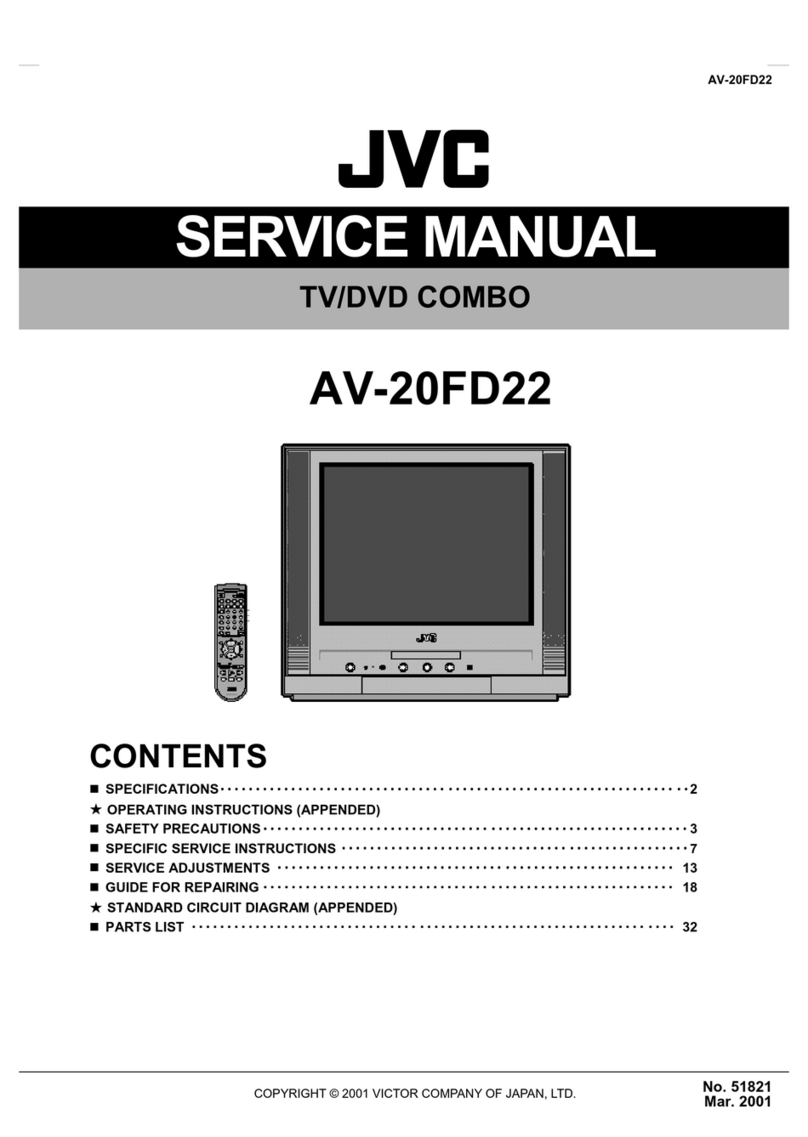
JVC AV-20FD22 User manual

No. 51821
Mar. 2001
A
V-20FD22
COPYRIGHT © 2001 VICTOR COMPANY OF JAPAN, LTD.
AV-20FD22
CONTENTS
SPECIFICATIONS㨯㨯㨯㨯㨯㨯㨯㨯㨯㨯㨯㨯㨯㨯㨯㨯㨯㨯㨯㨯㨯㨯㨯㨯㨯㨯㨯㨯㨯㨯㨯㨯
㨯㨯㨯㨯㨯㨯㨯㨯㨯㨯㨯㨯㨯㨯㨯㨯㨯㨯㨯㨯㨯㨯㨯㨯㨯㨯㨯㨯㨯㨯㨯㨯㨯㨯㨯㨯㨯㨯㨯㨯㨯㨯㨯㨯㨯㨯㨯㨯㨯㨯㨯㨯㨯㨯㨯㨯㨯㨯㨯㨯㨯㨯㨯㨯
㨯㨯㨯㨯㨯㨯㨯㨯㨯㨯㨯㨯㨯㨯㨯㨯㨯㨯㨯㨯㨯㨯㨯㨯㨯㨯㨯㨯㨯㨯㨯㨯 㨯㨯㨯㨯㨯㨯㨯㨯㨯㨯㨯㨯㨯㨯㨯㨯㨯㨯㨯㨯㨯㨯㨯㨯㨯㨯㨯㨯㨯㨯㨯㨯
㨯㨯㨯㨯㨯㨯㨯㨯㨯㨯㨯㨯㨯㨯㨯㨯㨯㨯㨯㨯㨯㨯㨯㨯㨯㨯㨯㨯㨯㨯㨯㨯㨯㨯㨯㨯㨯㨯㨯㨯㨯㨯㨯㨯㨯㨯㨯㨯㨯㨯㨯㨯㨯㨯㨯㨯㨯㨯㨯㨯㨯㨯㨯㨯
㨯㨯㨯㨯㨯㨯㨯㨯㨯㨯㨯㨯㨯㨯㨯㨯㨯㨯㨯㨯㨯㨯㨯㨯㨯㨯㨯㨯㨯㨯㨯㨯 㨯㨯
㨯㨯㨯㨯
㨯㨯2
䃨
OPERATING INSTRUCTIONS (APPENDED)
SAFETY PRECAUTIONS㨯㨯㨯㨯㨯㨯㨯㨯㨯㨯㨯㨯㨯㨯㨯㨯㨯㨯㨯㨯㨯㨯㨯㨯㨯㨯㨯㨯㨯㨯㨯㨯
㨯㨯㨯㨯㨯㨯㨯㨯㨯㨯㨯㨯㨯㨯㨯㨯㨯㨯㨯㨯㨯㨯㨯㨯㨯㨯㨯㨯㨯㨯㨯㨯㨯㨯㨯㨯㨯㨯㨯㨯㨯㨯㨯㨯㨯㨯㨯㨯㨯㨯㨯㨯㨯㨯㨯㨯㨯㨯㨯㨯㨯㨯㨯㨯
㨯㨯㨯㨯㨯㨯㨯㨯㨯㨯㨯㨯㨯㨯㨯㨯㨯㨯㨯㨯㨯㨯㨯㨯㨯㨯㨯㨯㨯㨯㨯㨯 㨯㨯㨯㨯㨯㨯㨯㨯㨯㨯㨯㨯㨯㨯㨯㨯㨯㨯㨯㨯㨯㨯㨯㨯㨯㨯㨯㨯
㨯㨯㨯㨯㨯㨯㨯㨯㨯㨯㨯㨯㨯㨯㨯㨯㨯㨯㨯㨯㨯㨯㨯㨯㨯㨯㨯㨯㨯㨯㨯㨯㨯㨯㨯㨯㨯㨯㨯㨯㨯㨯㨯㨯㨯㨯㨯㨯㨯㨯㨯㨯㨯㨯㨯㨯
㨯㨯㨯㨯㨯㨯㨯㨯㨯㨯㨯㨯㨯㨯㨯㨯㨯㨯㨯㨯㨯㨯㨯㨯㨯㨯㨯㨯 3
SPECIFIC SERVICE INSTRUCTIONS 㨯㨯㨯㨯㨯㨯㨯㨯㨯㨯㨯㨯㨯㨯㨯㨯㨯㨯㨯㨯㨯㨯㨯㨯㨯㨯㨯㨯㨯㨯㨯㨯
㨯㨯㨯㨯㨯㨯㨯㨯㨯㨯㨯㨯㨯㨯㨯㨯㨯㨯㨯㨯㨯㨯㨯㨯㨯㨯㨯㨯㨯㨯㨯㨯㨯㨯㨯㨯㨯㨯㨯㨯㨯㨯㨯㨯㨯㨯㨯㨯㨯㨯㨯㨯㨯㨯㨯㨯㨯㨯㨯㨯㨯㨯㨯㨯
㨯㨯㨯㨯㨯㨯㨯㨯㨯㨯㨯㨯㨯㨯㨯㨯㨯㨯㨯㨯㨯㨯㨯㨯㨯㨯㨯㨯㨯㨯㨯㨯 㨯㨯㨯㨯㨯㨯㨯㨯㨯㨯㨯㨯㨯㨯㨯㨯㨯
㨯㨯㨯㨯㨯㨯㨯㨯㨯㨯㨯㨯㨯㨯㨯㨯㨯㨯㨯㨯㨯㨯㨯㨯㨯㨯㨯㨯㨯㨯㨯㨯㨯㨯
㨯㨯㨯㨯㨯㨯㨯㨯㨯㨯㨯㨯㨯㨯㨯㨯㨯
SERVICE ADJUSTMENTS 㨯㨯㨯㨯㨯㨯㨯㨯㨯㨯㨯㨯㨯㨯㨯㨯㨯㨯㨯㨯㨯㨯㨯㨯㨯㨯㨯㨯㨯㨯㨯㨯
㨯㨯㨯㨯㨯㨯㨯㨯㨯㨯㨯㨯㨯㨯㨯㨯㨯㨯㨯㨯㨯㨯㨯㨯㨯㨯㨯㨯㨯㨯㨯㨯㨯㨯㨯㨯㨯㨯㨯㨯㨯㨯㨯㨯㨯㨯㨯㨯㨯㨯㨯㨯㨯㨯㨯㨯㨯㨯㨯㨯㨯㨯㨯㨯
㨯㨯㨯㨯㨯㨯㨯㨯㨯㨯㨯㨯㨯㨯㨯㨯㨯㨯㨯㨯㨯㨯㨯㨯㨯㨯㨯㨯㨯㨯㨯㨯 㨯㨯㨯㨯㨯㨯㨯㨯㨯㨯㨯㨯㨯㨯㨯㨯㨯㨯㨯㨯㨯㨯㨯㨯
㨯㨯㨯㨯㨯㨯㨯㨯㨯㨯㨯㨯㨯㨯㨯㨯㨯㨯㨯㨯㨯㨯㨯㨯㨯㨯㨯㨯㨯㨯㨯㨯㨯㨯㨯㨯㨯㨯㨯㨯㨯㨯㨯㨯㨯㨯㨯㨯
㨯㨯㨯㨯㨯㨯㨯㨯㨯㨯㨯㨯㨯㨯㨯㨯㨯㨯㨯㨯㨯㨯㨯㨯 13
GUIDE FOR REPAIRING 㨯㨯㨯㨯㨯㨯㨯㨯㨯㨯㨯㨯㨯㨯㨯㨯㨯㨯㨯㨯㨯㨯㨯㨯㨯㨯㨯㨯㨯㨯㨯㨯
㨯㨯㨯㨯㨯㨯㨯㨯㨯㨯㨯㨯㨯㨯㨯㨯㨯㨯㨯㨯㨯㨯㨯㨯㨯㨯㨯㨯㨯㨯㨯㨯㨯㨯㨯㨯㨯㨯㨯㨯㨯㨯㨯㨯㨯㨯㨯㨯㨯㨯㨯㨯㨯㨯㨯㨯㨯㨯㨯㨯㨯㨯㨯㨯
㨯㨯㨯㨯㨯㨯㨯㨯㨯㨯㨯㨯㨯㨯㨯㨯㨯㨯㨯㨯㨯㨯㨯㨯㨯㨯㨯㨯㨯㨯㨯㨯 㨯㨯㨯㨯㨯㨯㨯㨯㨯㨯㨯㨯㨯㨯㨯㨯㨯㨯㨯㨯㨯㨯㨯㨯㨯㨯
㨯㨯㨯㨯㨯㨯㨯㨯㨯㨯㨯㨯㨯㨯㨯㨯㨯㨯㨯㨯㨯㨯㨯㨯㨯㨯㨯㨯㨯㨯㨯㨯㨯㨯㨯㨯㨯㨯㨯㨯㨯㨯㨯㨯㨯㨯㨯㨯㨯㨯㨯㨯
㨯㨯㨯㨯㨯㨯㨯㨯㨯㨯㨯㨯㨯㨯㨯㨯㨯㨯㨯㨯㨯㨯㨯㨯㨯㨯 18
䃨
STANDARD CIRCUIT DIAGRAM (APPENDED)
PARTS LIST 㨯㨯㨯㨯㨯㨯㨯㨯㨯㨯㨯㨯㨯㨯㨯㨯㨯㨯㨯㨯㨯㨯㨯㨯㨯㨯㨯㨯㨯㨯㨯㨯
㨯㨯㨯㨯㨯㨯㨯㨯㨯㨯㨯㨯㨯㨯㨯㨯㨯㨯㨯㨯㨯㨯㨯㨯㨯㨯㨯㨯㨯㨯㨯㨯㨯㨯㨯㨯㨯㨯㨯㨯㨯㨯㨯㨯㨯㨯㨯㨯㨯㨯㨯㨯㨯㨯㨯㨯㨯㨯㨯㨯㨯㨯㨯㨯
㨯㨯㨯㨯㨯㨯㨯㨯㨯㨯㨯㨯㨯㨯㨯㨯㨯㨯㨯㨯㨯㨯㨯㨯㨯㨯㨯㨯㨯㨯㨯㨯 㨯㨯㨯㨯㨯㨯㨯㨯㨯㨯㨯㨯㨯㨯㨯㨯㨯㨯㨯㨯㨯㨯㨯㨯㨯㨯㨯㨯㨯㨯㨯㨯
㨯㨯㨯㨯㨯㨯㨯㨯㨯㨯㨯㨯㨯㨯㨯㨯㨯㨯㨯㨯㨯㨯㨯㨯㨯㨯㨯㨯㨯㨯㨯㨯㨯㨯㨯㨯㨯㨯㨯㨯㨯㨯㨯㨯㨯㨯㨯㨯㨯㨯㨯㨯㨯㨯㨯㨯㨯㨯㨯㨯㨯㨯㨯㨯
㨯㨯㨯㨯㨯㨯㨯㨯㨯㨯㨯㨯㨯㨯㨯㨯㨯㨯㨯㨯㨯㨯㨯㨯㨯㨯㨯㨯㨯㨯㨯㨯 㨯㨯㨯㨯
㨯㨯㨯㨯㨯㨯㨯㨯
㨯㨯㨯㨯 32
SERVICE MANUAL
TV/DVD COMBO

10
AV-20FD22
SERVICE MODE LIST
This unit provided with the following SERVICE MODES so you can repair, examine and adjust easily.
To enter the Service Mode, press both set key and remote control key.
Press both the VOL. key and remocon keys simultaneously for more than 1 second.
Press both the STOP key and remocon keys simultaneously for more than 3 seconds.
Set Key Remocon Key Operations
Initialization of the factory on TV.
NOTE: No operation at DVD mode.
Do not use this for the normal servicing.
Initialization of the factory on DVD.
NOTE: The operation will work only with STOP mode at DVD mode.
Do not use this for the normal servicing.
VOL. (-) MIN 1
POWER ON total hours are displayed on the screen.
Refer to the "CONFIRMATION OF USING HOURS".
NOTE: No operation at DVD mode.
Can be checked of the INITIAL DATA of MEMORY IC on TV.
Refer to the "NOTE FOR THE REPLACING OF MEMORY IC".
NOTE: No operation at DVD mode.
VOL. (-) MIN 3
VOL. (-) MIN 6
VOL. (-) MIN 0Releasing of V-CHIP PASSWORD.
Writing of EEPROM initial data on TV.
NOTE: No operation at DVD mode.
Do not use this for the normal servicing.
VOL. (-) MIN 9 Display of the Adjustment MENU on the screen.
Refer to the "ELECTRICAL ADJUSTMENT" (On-Screen Display Adjustment).
STOP 7
STOP 9 Self-Diagnosis will operate.
Refer to the "SELF-DIAGNOSIS"
Releasing of PARENTAL LOCK.
NOTE: The operation will work only with STOP mode at DVD mode.
VOL. (-) MIN 8
CONFIRMATION OF USING HOURS
POWER ON total hours can be checked on the screen. Total hours are displayed in 16 system of notation.
1.
2.
3.
Set the VOLUME to minimum.
Press both VOL. DOWN button on the set and Channel
button (6) on the remote control for more than 1 second.
After the confirmation of using hours, turn off the power.
INIT 00 83
0010
CRT ON
ADDRESS DATA
FIG. 1
Initial setting content of MEMORY IC.
POWER ON total hours.
= (16 x 16 x 16 x thousands digit value)
+ (16 x 16 x hundreds digit value)
+ (16 x tens digit value)
+ (ones digit value)

11
AV-20FD22
SELF-DIAGNOSIS
The Self-Diagnosis function will operate when both STOP button on the set and Channel button (9) on the remote control are
pressed simultaneously (for more than 3 seconds) at DVD LOGO screen with No Disc.
NOTE: No diagnosis of FL CHECK on the TV/DVD Player.
Diagnosis Items Diagnosis Method/Result Assumed Defects
1. FL CHECK "FL" will appear on the TV Monitor. Then all indicators will turn on and go out.
All light up (3 seconds) ---> All go out (1 second) ---> All light up all the time
Sight check if all the indicators will turn on or go out.
AV PCB
Power Block
2. SRAM CHECK "SRAM" will appear on the TV Monitor. Then non-specific data will be read
and written on the non-specific address.
If no problem on read and write, "OK" will appear. If any problems, "NG" will
appear.
Syscon PCB
3. VIDEO ENCODER CHECK Color bar and Black/White bar will appear alternately on the TV Monitor.
Color bar (1 second) ---> Black/White bar (1 second) ---> Color bar (1 second)
Sight check if correct color appears or Color and Black/White bar appears
alternately.
Syscon PCB
Power Block
4. TRAY CHECK "TRAY : OPEN" will appear on the TV Monitor. Then the tray will be opened
completely and "TRAY : CLOSE" will appear. Then the tray will be closed.
Sight check if the tray opens or closes correctly.
Syscon PCB
Drive Unit
Power Block
5. EEPROM CHECK "EEPROM" will appear on the TV Monitor. Then non-specific data will be read
and written on the non-specific address.
If no problem on read and write, "OK" will appear. If any problems, "NG" will
appear.
Syscon PCB
6. AUDIO DAC CHECK "ADAC" will appear on the TV Monitor. Then the pink noise will output from
RCA.
Lch ---> Rch ---> Lch+Rch
Check by ear if audio outputs correctly.
Syscon PCB
AV PCB
7. SDRAM "SDRAM" will appear on the TV Monitor. Then non-specific data will be read
and written on the non-specific address.
If no problem on read and write, "OK" will appear. If any problems, "NG" will
appear.
Syscon PCB
After the diagnosis, the results only for the SRAM, EEPROM and SDRAM will appear on the TV Monitor.
In case of OK, "PASS" will appear for the each diagnosis.
RESULT
PASS : SRAM
PASS : EEPROM
PASS : SDRAM
To finish the Self-Diagnosis, turn off the power on the Main unit.

12
AV-20FD22
NOTE FOR THE REPLACING OF MEMORY IC
If a service repair is undertaken where it has been required to change the MEMORY IC, the following steps should be taken to
ensure correct data settings while making reference to TABLE 1.
F9 43 05 01 F1 23 27 F7 81 CD
+0 +1 +2 +3 +4 +5 +6 +7 +8 +9 +A +B +C +D +E +FINI
64 67 69 2A 6B 6C 6D 6E 6F
54 74 55 75 75 56 56 76 76 57
78 59 59 79 79 5A 5A 7A 7A 5B
7C 5D 7D 7D 5E 5E 7E 7E 5F
D9 3F 3F 40 61 6300
10 26 70 71 52 72 53 73
20 57 77 77 58 58 78
30 5B 7B 7B 5C 5C 7C
40 5D 5F 5F 7F 7F BF B7
B9 A1 C5 00 C7 00 00 00 97
D9 B0 84 88 9A 9F 2A 5A 00 00
50 AC AF 7F A8 B8 B4 7A
60 00 10 --- --- --- ---
INIT 00 83
0010
CRT ON
ADDRESS DATA
3.
4.
5.
6.
7.
8.
The unit will now have the correct DATA for the new MEMORY IC.
Table 1
1.
2.
Fig. 1
Enter DATA SET mode by setting VOLUME to minimum.
Press both VOL. DOWN button on the set and Channel button (6) on the remote control for more than 1 second.
ADDRESS and DATA should appear as FIG 1.
ADDRESS is now selected and should "blink". Using the VOL. UP/DOWN button on the remote, step through the
ADDRESS until required ADDRESS to be changed is reached.
Press ENTER to select DATA. When DATA is selected, it will "blink".
Again, step through the DATA using VOL. UP/DOWN button until required DATA value has been selected.
Pressing ENTER will take you back to ADDRESS for further selection if necessary.
Repeat steps 3 to 6 until all data has been checked.
When satisfied correct DATA has been entered, turn POWER off (return to STANDBY MODE) to finish DATA input.

13
AV-20FD22
ELECTRICAL ADJUSTMENTS
1.
Read and perform these adjustments when repairing the
circuits or replacing electrical parts or PCB assemblies.
CAUTION
•
•
•
•
Use an isolation transformer when performing any
service on this chassis.
Before removing the anode cap, discharge electricity
because it contains high voltage.
When removing a PCB or related component, after
unfastening or changing a wire, be sure to put the wire
back in its original position.
Inferior silicon grease can damage IC's and transistors.
When replacing IC's and transistors, use only specified
silicon grease.
Remove all old silicon before applying new silicon.
Prepare the following measurement tools for electrical
adjustments.
BEFORE MAKING ELECTRICAL
ADJUSTMENTS
1. Oscilloscope
2. Digital Voltmeter
3. AC Voltmeter
4. Pattern Generator
2. BASIC ADJUSTMENTS
2-1: CONSTANT VOLTAGE
1.
2.
3.
4.
Set condition is AV MODE without signal.
Using the remote control, set the brightness and contrast
to normal position.
Connect the digital voltmeter to TP401.
Adjust the VR502 until the digital voltmeter is 111 ±0.5V.
Fig. 1-2
NO.
01
02
03
04
05
06
07
08
09
10
11
12
13
14
15
16
17
18
19
20
21
22
23
24
25
26
27
28
29
30
31
32
33
34
35
36
FUNCTION
BRI. AV(CENT.)
BRI. AV(MAX)
BRI. AV(MIN)
COL. AV(CENT.)
COL. AV(MAX)
COL. AV(MIN)
TINT AV
SUB CONTRAST AV
CONT. AV(CENT.)
CONT. AV(MAX)
CONT. AV(MIN)
SHARPNESS AV
BRI. DVD(CENT.)
BRI. DVD(MAX)
BRI. DVD(MIN)
COL. DVD(CENT.)
COL. DVD(MAX)
COL. DVD(MIN)
TINT DVD
SUB CONTRAST DVD
CONT. DVD(CENT.)
CONT. DVD(MAX)
CONT. DVD(MIN)
SHARPNESS DVD
BRI. GAME(CENT.)
BRI. GAME(MAX)
BRI. GAME(MIN)
CONT. GAME(CENT.)
CONT. GAME(MAX)
CONT. GAME(MIN)
TUNING V MUTE
POWER ON V MUTE
INPUT LEVEL
SEPARATION L
SEPARATION H
CUT OFF
NO
.
37
38
39
40
41
42
43
44
45
46
47
48
49
50
51
52
53
54
55
56
57
58
59
60
61
62
63
64
65
66
67
68
69
70
71
72
FUNCTION
R CUT OFF
G CUT OFF
B CUT OFF
G DRIVE
B DRIVE
BRIGHTNESS(CENT.)
BRIGHTNESS(MAX)
BRIGHTNESS(MIN)
COLOR(CENT.)
COLOR(MAX)
COLOR(MIN)
TINT
SUB CONTRAST
CONTRAST(CENT.)
CONTRAST(MAX)
CONTRAST(MIN)
SHARPNESS
RGB CONTRAST
H POSITION
V POSITION
V SIZE
V LINEARITY
V S CORRECTION
EW PARABOLA CORR.
EW TRAPEZIUM CORR.
H SIZE
V EHT
H EHT
RF AGC
V CENTERING
CORNER CORR. TOP
CORNER CORR. BTM
OSD H
FM LEVEL
TEST PWM
TEST TONE CONTROL
2-2: RF AGC
1.
2.
3.
4.
5.
Receive the VHF HIGH (63dB).
Place the set with Aging Test for more than 15 minutes.
Connect the digital voltmeter between the pin 5 of
CP101 and the pin 1 of CP101.
Activate the adjustment mode display of Fig. 1-1 and
press the channel button (29) on the remote control to
select "AGC".
Press the VOL. UP/DOWN button on the remote
control until the digital voltmeter is 2.7 ±0.05V.
2-3: CUT OFF
1.
2.
3.
4.
5.
6.
Adjust the unit to the following settings.
G DRIVE=3F, B DRIVE=3F, R CUT OFF=7F, G CUT
OFF=7F, B CUT OFF=7F
Place the set with Aging Test for more than 15 minutes.
Set condition is AV MODE without signal.
Using the remote control, set the brightness and contrast
to normal position.
Activate the adjustment mode display of Fig. 1-1 and
press the channel button (72) on the remote control to
select "CUT OFF".
Adjust the Screen Volume until a dim raster is obtained.
On-Screen Display Adjustment
In the condition of NO indication on the screen.
Press the VOL. DOWN button on the set and the
Channel button (9) on the remote control for more than
1 second to appear the adjustment mode on the screen
as shown in Fig. 1-1.
1.
Fig. 1-1
Use the Channel UP/DOWN button or Channel button
(1-0) on the remote control to select the options shown
in Fig. 1-2.
Press the TV MENU button on the remote control to
end the adjustments.
2.
3.
01 RCUT
3E
Function
Step No.
SERVICE ADJUSTMENT
Other manuals for AV-20FD22
2
Table of contents
Other JVC TV DVD Combo manuals

JVC
JVC 1EMN24860 User manual

JVC
JVC LT19D200 - 19" LCD TV User manual

JVC
JVC LT-42B300 Technical manual

JVC
JVC LT-32DM21 User manual

JVC
JVC LT-32C345A User manual

JVC
JVC LT-19A210 User manual

JVC
JVC LT-22HD7WU User manual

JVC
JVC 0808TKH-FU-FU User manual

JVC
JVC LT-19DM21 User manual

JVC
JVC AV-20FD24 User manual