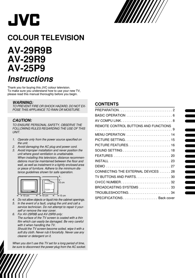
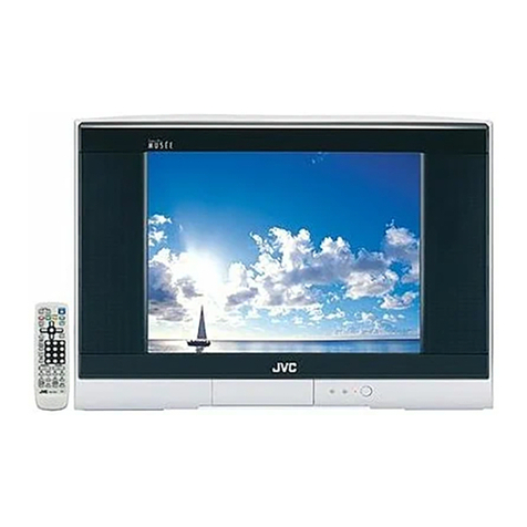
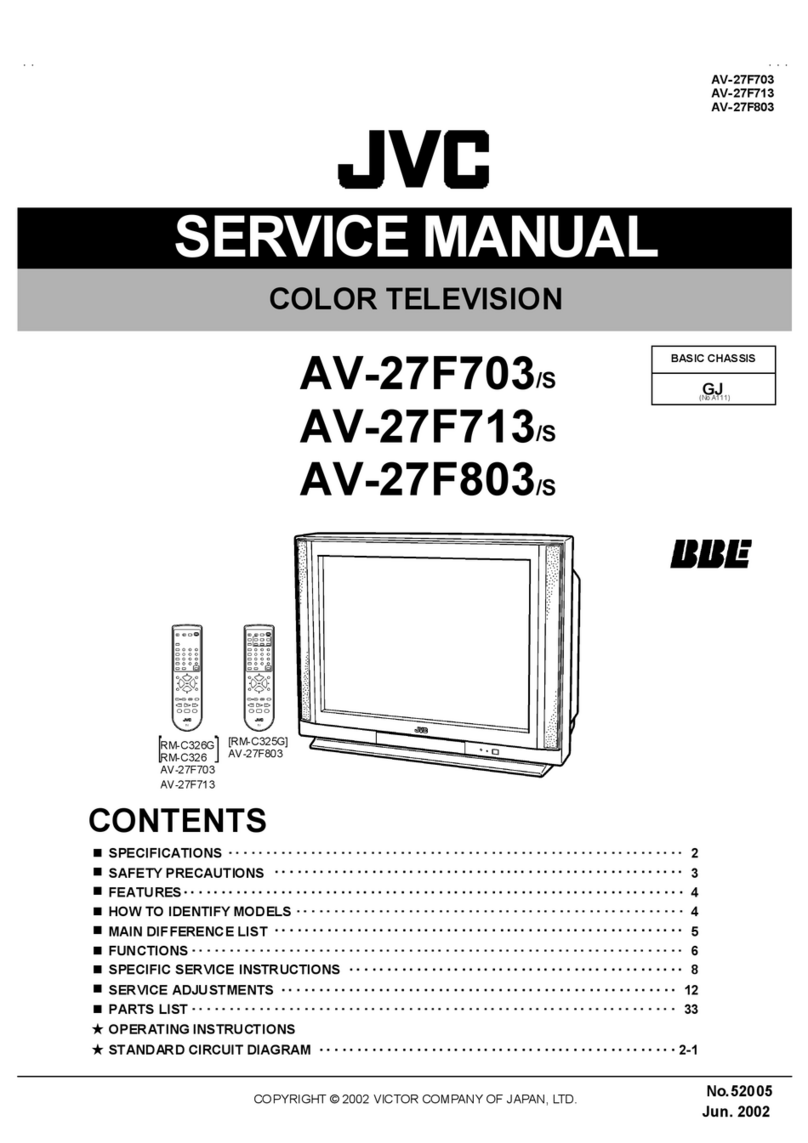
JVC AV-27320 User manual

No.51937
May. 2002
AV-2732
0
AV-2733
0
AV-27S3
3
1COPYRIGHT © 2002 VICTOR COMPANY OF JAPAN, LTD.
May 2002
AV-27320/S/R
AV-27330/S/R
AV-27S33/S/R
CONTENTS
!SPECIFICATIONS ・・・・・・・・・・・・・・・・・・・・・・・・・・・・・・・・
・・・・・・・・・・・・・・・・・・・・・・・・・・・・・・・・・・・・・・・・・・・・・・・・・・・・・・・・・・・・・・・・
・・・・・・・・・・・・・・・・・・・・・・・・・・・・・・・・・・・・・・・・・・・・・・・・・・・・・・・・・・・・・
・・・・・・・・・・・・・・・・・・・・・・・・・・・・・・・・・・・・・・・・・・・・・・・・・・・・・・・・・・
・・・・・・・・・・・・・・・・・・・・・・・・・・・・・ 2
!SAFETY PRECAUTIONS ・・・・・・・・・・・・・・・・・・・・・・・・・・・・・・・・
・・・・・・・・・・・・・・・・・・・・・・・・・・・・・・・・・・・・・・・・・・・・・・・・・・・・・・・・・・・・・・・・
・・・・・・・・・・・・・・・・・・・・・・・・・・・・・・・・・・・・・・・・・・・・・・・・・・・・・・・
・・・・・・・・・・・・・・・・・・・・・・・・・・・・・・・・・・・・・・・・・・・・・・
・・・・・・・・・・・・・・・・・・・・・・・ 3
!FEATURES・・・・・・・・・・・・・・・・・・・・・・・・・・・・・・・・
・・・・・・・・・・・・・・・・・・・・・・・・・・・・・・・・・・・・・・・・・・・・・・・・・・・・・・・・・・・・・・・・
・・・・・・・・・・・・・・・・・・・・・・・・・・・・・・・・・・・・・・・・・・・・・・・・・・・・・・・・・・・・・・・・
・・・・・・・・・・・・・・・・・・・・・・・・・・・・・・・・・・・・・・・・・・・・・・・・・・・・・・・・・・・・・・・・
・・・・・・・・・・・・・・・・・・・・・・・・・・・・・・・・・・・
・・・・・・
・・・ 4
!HOW TO IDENTIFY MODELS ・・・・・・・・・・・・・・・・・・・・・・・・・・・・・・・・
・・・・・・・・・・・・・・・・・・・・・・・・・・・・・・・・・・・・・・・・・・・・・・・・・・・・・・・・・・・・・・・・
・・・・・・・・・・・・・・・・・・・・・・・・・・・・・・・・・・・・・・・・・・・・・・・・・・・・
・・・・・・・・・・・・・・・・・・・・・・・・・・・・・・・・・・・・・・・・
・・・・・・・・・・・・・・・・・・・・ 4
!MAIN DIFFERENCE LIST ・・・・・・・・・・・・・・・・・・・・・・・・・・・・・・・・
・・・・・・・・・・・・・・・・・・・・・・・・・・・・・・・・・・・・・・・・・・・・・・・・・・・・・・・・・・・・・・・・
・・・・・・・・・・・・・・・・・・・・・・・・・・・・・・・・・・・・・・・・・・・・・・・・・・・・・・・
・・・・・・・・・・・・・・・・・・・・・・・・・・・・・・・・・・・・・・・・・・・・・・
・・・・・・・・・・・・・・・・・・・・・・・ 5
!FUNCTIONS ・・・・・・・・・・・・・・・・・・・・・・・・・・・・・・・・
・・・・・・・・・・・・・・・・・・・・・・・・・・・・・・・・・・・・・・・・・・・・・・・・・・・・・・・・・・・・・・・・
・・・・・・・・・・・・・・・・・・・・・・・・・・・・・・・・・・・・・・・・・・・・・・・・・・・・・・・・・・・・・・・・
・・・・・・・・・・・・・・・・・・・・・・・・・・・・・・・・・・・・・・・・・・・・・・・・・・・・・・・・・・・・・・・・
・・・・・・・・・・・・・・・・・・・・・・・・・・・・・・・・・・
・・・・
・・ 6
!SPECIFIC SERVICE INSTRUCTIONS ・・・・・・・・・・・・・・・・・・・・・・・・・・・・・・・・
・・・・・・・・・・・・・・・・・・・・・・・・・・・・・・・・・・・・・・・・・・・・・・・・・・・・・・・・・・・・・・・・
・・・・・・・・・・・・・・・・・・・・・・・・・・・・・・・・・・・・・・・・・・・・・
・・・・・・・・・・・・・・・・・・・・・・・・・・
・・・・・・・・・・・・・ 8
!SERVICE ADJUSTMENTS ・・・・・・・・・・・・・・・・・・・・・・・・・・・・・・・・
・・・・・・・・・・・・・・・・・・・・・・・・・・・・・・・・・・・・・・・・・・・・・・・・・・・・・・・・・・・・・・・・
・・・・・・・・・・・・・・・・・・・・・・・・・・・・・・・・・・・・・・・・・・・・・・・・・・・・・
・・・・・・・・・・・・・・・・・・・・・・・・・・・・・・・・・・・・・・・・・・
・・・・・・・・・・・・・・・・・・・・・ 12
!PARTS LIST ・・・・・・・・・・・・・・・・・・・・・・・・・・・・・・・・
・・・・・・・・・・・・・・・・・・・・・・・・・・・・・・・・・・・・・・・・・・・・・・・・・・・・・・・・・・・・・・・・
・・・・・・・・・・・・・・・・・・・・・・・・・・・・・・・・・・・・・・・・・・・・・・・・・・・・・・・・・・・・・・・・
・・・・・・・・・・・・・・・・・・・・・・・・・・・・・・・・・・・・・・・・・・・・・・・・・・・・・・・・・・・・・・・・
・・・・・・・・・・・・・・・・・・・・・・・・・・・・・・・・・
・・
・31
★OPERATING INSTRUCTIONS
★STANDARD CIRCUIT DIAGRAM ・・・・・・・・・・・・・・・・・・・・・・・・・・・・・・・・
・・・・・・・・・・・・・・・・・・・・・・・・・・・・・・・・・・・・・・・・・・・・・・・・・・・・・・・・・・・・・・・・
・・・・・・・・・・・・・・・・・・・・・・・・・・・・・・・・・・・・・・・・・・・・・・・・
・・・・・・・・・・・・・・・・・・・・・・・・・・・・・・・・
・・・・・・・・・・・・・・・・2- 1
SERVICE MANUAL
COLOR TELEVISION
BASIC CHASSIS
FE
[RM-C255]
AV -2 73 30
AV -2 7S3 3
[RM-C205]
AV -2 73 20

No.51937
A
V-27320
A
V-27330
A
V-27S33
2
SPECIFICATIONS
Contents
Items AV-273 20/S
AV-2 7320/R
AV-2 7330/S
AV-2 7330/R
AV -2 7S 3 3/ S
AV -2 7S 3 3/ R
Dimensions (W×
××
×H×
××
×D) 25 -3/4 ” ×23”-3/8”×19-1/2” (654mm×59 3m m ×4 94mm)
Mass 68.5 Ibs (31.1 kg)
TV System and Color System
TV RF System
Color Sy st em
Sound System
CCIR(M)
NTSC
BTS C S ystem ( Mul ti -Ch an nel S ou nd )
TV Receiving Channels and Frequency
VL Ba nd
VH Band
UHF Band
(02~0 6) 54 MH z~88MHz
(07~1 3) 17 4M Hz~21 6MHz
(14~6 9) 47 0M Hz~80 6MHz
CATV Receiving Channels and Frequency
Low Band
Hi
g
h B an d
Mid Band
Su
p
er Ba nd
H
yp
er Ba nd
Ul tr a B an d
Sub Mid Band
TV/CATV Total Channel
(02~06, A-8) by (02~06 &0 1)
(07~13) by (07
~13)
(A~1) b y (14~22)
(J~
W) by (23~36)
(W +1~W + 28) b y (3 7~64 )
(W +29 ~
W +84) b y ( 65 ~1 25)
(A8, A4~A1) by (01, 96~99 )
18 1 C ha nn els
Intermediate Frequency
Vide o IF Car rier
Sound IF Carrier
Color Sub Carrier
45 .75 MHz
41.25MHz (4.5MHz)
3.58MHz
Power Input
Power Consumption
12 0V AC , 6 0H z
11 3W
Pictur e Tube
Hi g h Vo lt ag e
27 ” ( 6 8cm ) Mea sured Diag on all y
28 .0 kV±1.3kV (at zero beam current)
Spe ake r
Au dio Power Output
2“×3 -1/ 2” ( 5×9cm) Ovaltype×2
1.2 W + 1.2 W
Input terminals
Input 1 S-Video
Video(V)
Component (V/Y, PB
, PR)
Au dio
(
L
,
R
)
Y: 1Vp- p P ositi ve ( n eg ative s ync p r ovi ded , w h en ter min at ed wi th 7 5Ω)
C: 0. 28 6Vp-p (burst signal, when t erminated with 75Ω)
1V p-p, 75Ω( RCA pi n j ack) [AV- 2 73 30/ S,R A V- 27 S33 /S, R]
1V p- p 7 5Ω( pos iti ve sync) [A V- 27 32 0/S ,R]
50 0m Vrms ( -4 dBs ), Hig h I mp ed anc e ( RCA pi n jack)
Input 2 Video(V)
Au dio (L , R )
Component (V/Y, P
B, PR)
Audio(L, R)
1V p-p, 75Ω( RCA pi n j ack) [AV- 2 73 20/ S,R ]
50 0m Vrms ( -4 dBs ), Hig h I mp ed anc e ( RCA pi n jack) [AV -2 73 20 /S,R ]
1V p- p 7 5Ω( pos iti ve sync) [A V- 27 33 0/S ,R AV- 2 7S3 3/ S,R ]
500mVrms ( -4dBs ), High Impedance (RCA pin jack) [AV-27330/S,R AV-27S33/S,R]
In
p
ut 3
(
Fr on t
)
Video
(
V
)
Au dio
(
L
,
R
)
1V p-p, 75Ω( RCA pi n j ack) [AV- 2 73 30/ S,R A V- 27 S33 /S, R]
500mVrms ( -4dBs ), High Impedance (RCA pin jack) [AV-27330/S,R AV-27S33/S,R]
Output ter minals
Variable Audio Output (R/L) More than 0~1550mVrms (+6dBs)
Low impedance (400Hz when modulated 100%) (RCA pin jack)
An ten na terminal 75 Ω(VHF/UHF) Terminal, F-T ype Connector
Remote Control Unit RM- C20 5 ( AA /R 6/UM- 3 b att ery×2) [A V- 27 32 0/S ,R]
RM- C25 5 ( AA /R 6/UM- 3 b att ery×2) [AV-27330/S,R AV-27S33/S ,R]
Design & sp eci ficatio ns ar e su bje ct to chang e wi thou t no tice.
(54MHz~80 4M Hz)

No. 51937
A
V-27320
A
V-27330
A
V-27S33
3
SAFETY PRECAUTIONS
1. The d esign of t hi s p ro du ct c ont ai ns spec i al h ar dware, m an y
ci rcu it s a nd co mp on ent s s peci all y for saf ety pur p oses. For
continued protection, no changes should be made to the
or igi na l des ig n u nl ess a uth or ized in wri ti ng by t he m an uf actu re r.
Rep lacem en t par ts m ust be i d ent ic al t o t hos e u sed in th e
or igi na l circui t s. S er vic e sho uld be per f or me d b y qu al ifi ed
p ers onn el o nl y.
2. Al te r ation s of th e desi g n o r ci rcu i tr y of th e p r odu cts s hou ld n ot
b e m ad e. A ny de sign al te ra ti ons o r ad di tio ns wi ll vo id th e
manufacturer's warranty and will further relieve the
m anu fact urer of r esp ons ib i li t y f or pe rs ona l i n ju r y or p r ope rt y
d am age r esu lt in g t heref r om.
3. M an y e l ectr ical an d m ech an ic al pa rt s in th e p r odu cts h ave
sp ecial saf ety- relat ed c har act er is tics. Th ese char ac ter istics are
oft en n ot e vi d en t fr om visu al in spe ction no r can t he pr ote cti on
aff orde d by th em n ecess ar il y be o bta in ed b y using
r eplac em ent co mp on ent s ra ted for h ig her vo l tag e, wa ttag e, etc.
Rep lacem en t pa rt s wh ic h h ave t hes e sp eci al s afet y
ch ar acter isti cs a re i d entifi e d in th e par ts l ist of S ervi ce m an ua l.
Electrical components having such features are identified
by shading on the schematics and by (!
!!
!) on the parts list
in S ervice manual . T h e u se of a su bst itu te re plac em en t which
does not have the same safety charact eristics as the
r eco mm en de d re plac em en t pa rt sho wn in the pa rts list of
Se rvice ma nu al m ay c aus e sh ock, f ir e, or o th er haz ar ds.
4. Use isola t ion tr ansf orme r wh en hot c h ass is .
The chassis and any sub-chassis contained in s ome products
ar e c on nect ed to on e si de of th e AC p ow er l ine . An i sol a ti on
tr ansf ormer of ad equ ate cap acity sh ou ld be i nser t ed bet we en
th e p r odu ct and t he AC p ow er su pp ly p oi nt while p er for ming
an y ser vi ce on so me pr o ducts wh en th e H OT ch assis is
exp ose d.
5. Do n't short between the LIVE side ground and ISOLATED
(NEUTRAL) side ground or EARTH side ground when
repairing.
So m e m od el's p ow er c ir cuit is par t ly di f fer en t in t he GND. Th e
diff erenc e of t he GND is sh own by th e LI VE : (") side GND,
th e ISO LATED( NEUTRA L) : (#) sid e GND an d EARTH : ( $)
si de GN D. Don 't sho rt be tw ee n t he LIVE sid e GN D a nd
ISO LATE D(NEUTRAL) side GND or EARTH side GND a nd
never measure with a measuring apparatus (oscilloscope etc.)
th e LI VE side GND a nd ISO LATED(NEUTRA L) side G ND or
EARTH sid e GND at the s ame time.
If above note will not be kept, a fuse or any parts will be brok en.
6. If an y re pa ir h as b ee n m ad e to th e ch assi s, it i s re com m end ed
th at t he B1 se tti n g sh ou ld b e chec ked or ad juste d (S ee
ADJUSTM ENT OF B 1 POW E R SU PPLY).
7. The hi g h volt ag e a pp lied t o th e pictu re tu be mu st co nfo rm wi th
that specified in Service manual. Excessive high voltage can
cau se an i ncr ea se i n X-Ra y em ission , a rcin g and p ossi ble
com po ne nt d am ag e, th er ef or e op er ati o n un der excess ive hi gh
vol ta ge c ond it ions sh ou ld be ke pt to a m in i mu m, or sh ou l d be
pr eve nt ed. I f seve re arc in g occu rs, remove th e AC p ower
immediately and determine the cause by visual inspection
( in cor rect insta ll a tion , crac ked o r m elte d high voltag e h ar ness,
p oor s olde rin g, etc. ). T o ma in ta in the pr op er m inim um le vel of
soft X-Ray emission, components in the high voltage circuitry
includ ing the pictu r e tu be mu st be the exa ct r ep lacem en ts or
alte rn at i ves a ppr o ved b y th e ma nuf actu r er of th e co mp l ete
pr od uct.
8. Do n ot c hec k high volta ge by d r awin g a n ar c. U s e a hi gh
vol ta ge m ete r or a h i gh vol t age p ro be w ith a VTVM . Disch ar ge
th e p ictu r e tu be bef ore a tte mp ting me ter co nne cti on , b y
con nec ting a clip lead t o th e grou nd fr am e a nd conn ecting t he
oth er e nd of t he lead th r oug h a 10 kΩ2W resist or to t he ano de
bu tto n.
9. W hen se rvi ce is r equ ir ed, ob serve th e o rig in al l ea d dr ess.
Extr a p r ecau tion sh ou ld be given t o assu re corre ct lea d dr es s
in the h i gh volta ge c ir cu it ar ea . W her e a sh ort circuit ha s
occu rr e d, th ose c omp on en ts th at i nd ic ate evi den ce of
overheating should be replaced. Always use the
m anu fact urer's r eplace m ent comp on ents.
10 . Isolation Check
(Safety for Electrical Shock Hazard)
Af ter r e-a ssem bling th e pr od uct , al ways pe rf or m an i so l ati on
ch eck on th e expo sed m eta l p ar ts of th e c abi n et ( ant en na
ter m ina ls, vide o/a ud i o in pu t and out put t er min al s, C on tr ol
knobs, metal cabinet, screwheads, earphone jack, control
sh afts, etc.) to be sur e th e pr o duct is saf e t o op er at e with out
d ang er of el ect ri ca l shoc k.
(1) Dielectric Strength Test
The is ol at io n b etw e en the AC pr ima r y circu it and al l m eta l par ts
exp ose d t o th e us er, par t icu larly an y expo sed m etal p ar t h aving
a retur n pat h to the ch assis shou ld withst and a volta ge of
11 00V AC ( r.m .s.) f or a p er iod of on e sec ond .
(. . . . Withs tand a volta ge of 1100V A C (r.m. s.) to an appliance
r ate d up to 1 20V , a nd 3 00 0V AC ( r.m. s.) t o an ap plianc e r a ted
200V or more, for a period of one second.)
Thi s m eth od of test r e qu ires a t est eq ui p me nt n ot g en er all y
fou nd i n t he ser vi ce t ra de.
(2) Leakage Current Check
Plug t he A C line c ord direct ly int o th e AC ou tlet ( do not u se a
lin e is olation tr a nsf orm er dur ing t hi s che ck.) . U sing a "L eaka ge
Current T est er", m ea sur e t he l ea kag e cur ren t fr om each
exp ose d m eta l par t of th e ca bine t, p ar tic ul arly an y expo sed
metal part having a return p ath to t he chassis , to a kn own good
ea rt h gr o und ( wa ter p i pe, etc.) . A ny l ea kag e cur r en t m ust not
exceed 0. 5mA AC ( r.m. s.).
Howeve r, in t ro pical a r ea, thi s m ust no t e xc eed 0 .2m A AC
(r.m.s. ).
"
""
"Alte rn ate Che ck M ethod
Plug t he A C line c ord direct ly int o th e AC ou tlet ( do not u se a
line isolation transformer during this check.). Use an AC
vol tm et er h avi ng 100 0 o hm s per volt or m ore sen siti vit y i n the
fol lo win g ma nne r. Con nec t a 1 50 0Ω1 0W r esistor pa ra lle led
by a 0.15μF AC -typ e cap acitor b etw e en an exp ose d m eta l
p art an d a kno wn g o od earth gr ou nd ( wate r pi p e, et c.).
M easu r e th e A C vo ltag e across th e r esist or wit h t he AC
voltmeter. Move the res istor connection to each exposed metal
part, particularly any exposed metalpart having areturnpath to
th e ch assis , an d m ea sur e t he A C vol ta ge acr oss th e r esi sto r.
Now, r eve rs e th e pl u g i n t he A C out let a nd r ep e at e ach
m easu r em en t. An y vol ta ge me asu re d m ust not exce ed 0.7 5V
AC (r.m. s.). This corresp on ds t o 0 .5 mA A C (r.m. s.).
Howeve r, in tr op ic al ar ea, this m ust n ot excee d 0 .3V AC
(r.m.s. ). This corresp onds t o 0 .2mA A C ( r.m.s.).
0.15μF A C-T YPE
1500Ω10W
GOOD
EARTH
GR OUND
PLACE THIS PROBE
ON E A CH EX PO SE D
ME T AL PA R T
ACVOLTMETER
(HAVING 1000 Ω/V,
OR MOR E SENSIT IVITY)
11 . High voltage hold down circuit check.
Af ter r ep air of th e high volt ag e h old d ow n ci rcuit, th is circu i t
sh al l b e c hec ked to op er ate correctly.
See item "Ho w to check the high voltage hold down
cir cuit".
A V
This mark shows a fast
operating fuse, the
letters indicated below
show the rating.

No.51937
A
V-27320
A
V-27330
A
V-27S33
4
FEATURES
"New chas sis design en ables use of a single board with simplif ied
circuit ry.
"Users can m ake fun t o c onnect th e Digital Video Disk player wit h
the comp onent video sig nal i npu t ter mi nal.
"Pr ovid ed w ith miniatu re tuner ( TV/C ATV ).
"Mu lt if unct ion al remote con tro l p ermits pi ctu re a djustm ent.
"Ad option of t he CHANNEL GU ARD fu ncti on pr even ts th e specifi c
chan nel s fr om bei ng sel ected, unless th e “ ID nu mbe r” i s key in .
"I2C bus control utilizes single chip ICs.
"Ad option of the VIDEO STATUS f unc tion .
"Adoption of the ON/OFF TIMER function.
"Built-in V-CHIP system.
"With 75ΩV/U in c ommon (F-Type) ANT Termin al.
"SL EEP TIME R f or setting in real t ime.
"Clos ed-caption b roa dcasts can be vi ewed.
"Bu il t- in MT S s ys tem.
"Built-in HYPER-SURROUND system.
"S-VIDEO input terminal for taking best advantag e of S uper VHS .
"Var iabl e Au di o outp ut te rmin al.
"3 L INE D igi tal Com b f ilter Im prove d pi ctu re q ual ity.
HOW TO IDENTIFY MODELS
The di ffer enc e betw een AV -27 320 /S an d AV -2 732 0/R i s in th e PIC TURE TUBE.
As t he r esult of the diffe rence in pictu re t ube, the MAIN PW B also dif fers.
In the same way, the d if fer ence betw een 2 733 0/S and A V- 273 30/R,2 7S3 3/S a nd 2 7S3 3/R i s in the PIC TU RE T UBE t oo.
!MODEL
Parts name
AV -27 320 /S
AV -2 733 0/S
AV -2 7S3 3/S
AV -27 320 /R
AV -2 733 0/R
AV -2 7S3 3/R
!RATING LABEL LC31139-0 01A-A ←
←←
←
Ind icat ed AV -27 230
or AV- 27 330
orAV-27S33
Ind icat ed AV -27 230
or AV- 27 330
orAV-27S33
Indic ated “S” Indic ated “R”

No.51937
A
V-27320
A
V-27330
A
V-27S33
5
MAIN DIFFERENCE LIST
!
!!
!Model name
Parts Name
AV-2 7320/S AV-2 73 20/R
MA IN PW B SFE-10 06A -M 2 SFE-10 07A -M 2
!IT C T UBE A6 8QD N891 X001 A6 8AD T25 X01
!POW ER KN OB LC30 376 -0 01A- A
!PU SH KN OB LC30 271 -0 01A- A
!REAR COVE R LC10 082 -0 04A- A
!FR ON T CA BINET LC10 081 -0 05B- A
JVC M ARK CM4 8006 -0 06-C
REMOTE CONTROL UNIT RM-C205-1C
!
!!
!
Model name
Parts Name
AV-2 7330/S AV-2 73 30/R
MA IN PW B SFE-10 04A -M 2 SFE-10 05A -M 2
!IT C T UBE A6 8QD N891 X001 A6 8AD T25 X01
!POW ER KN OB LC30 376 -0 01A- A
!PU SH KN OB LC30 271 -0 01A- A
!REAR COVE R LC10 082 -0 03A- A
!FR ON T CA BINET LC10 081 -0 04B- A
JVC M ARK CM4 8006 -0 06-C
REMOTE CONTROL UNIT RM-C255-1H
!
!!
!Model name
Parts Name
AV -2 7S 3 3/S AV -2 7S 3 3/R
MA IN PW B SFE-10 04A -M 2 SFE-10 05A -M 2
!IT C T UBE A6 8QD N891 X001 A6 8AD T25 X01
!POW ER KN OB LC30 376 -0 04A- A
!PU SH KN OB LC30 271 -0 04A- A
!REAR COVE R LC10 082 -0 03A- A
!FR ON T CA BINET LC10 081 -0 08A- A
JVC M ARK CM4 8006 -0 07-C
REMOTE CONTROL UNIT RM-C255-1H
Other manuals for AV-27320
1
This manual suits for next models
8
Table of contents
Other JVC TV manuals