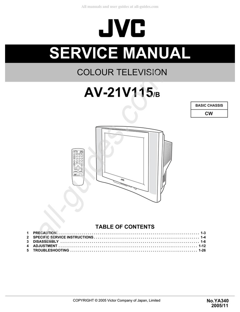
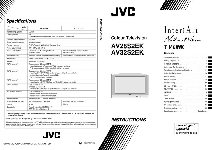
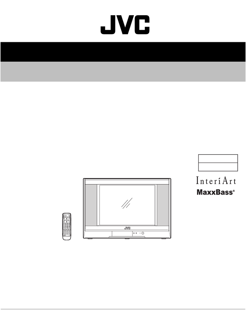
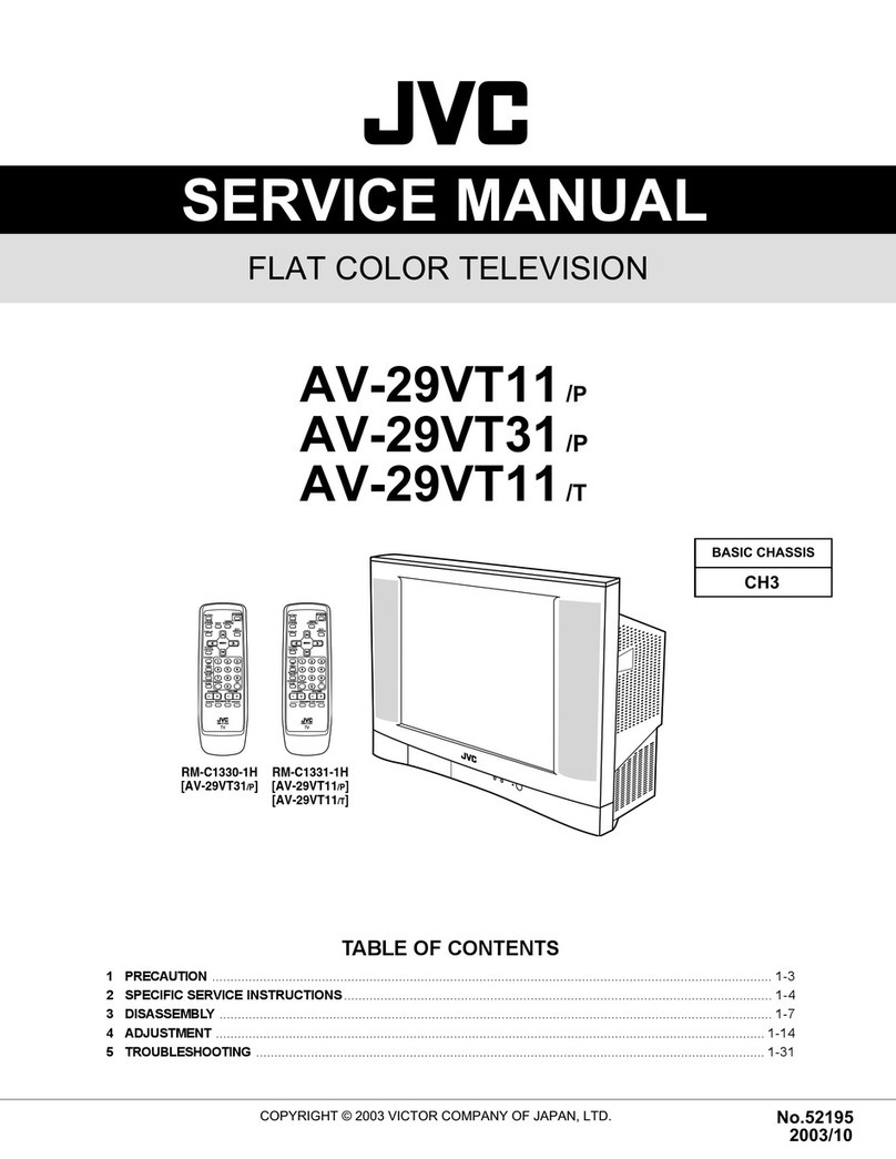
JVC InteriArt AV-29QT4SU User manual

SERVICE MANUAL
COPYRIGHT © 2006 Victor Company of Japan, Limited No.YA085C
2006/7
COLOUR TELEVISION
YA085C20067
AV-29QT4SU/D
TABLE OF CONTENTS
1 PRECAUTION. . . . . . . . . . . . . . . . . . . . . . . . . . . . . . . . . . . . . . . . . . . . . . . . . . . . . . . . . . . . . . . . . . . . . . . . . 1-3
2 SPECIFIC SERVICE INSTRUCTIONS . . . . . . . . . . . . . . . . . . . . . . . . . . . . . . . . . . . . . . . . . . . . . . . . . . . . . . 1-3
3 DISASSEMBLY . . . . . . . . . . . . . . . . . . . . . . . . . . . . . . . . . . . . . . . . . . . . . . . . . . . . . . . . . . . . . . . . . . . . . . . 1-4
4 ADJUSTMENT . . . . . . . . . . . . . . . . . . . . . . . . . . . . . . . . . . . . . . . . . . . . . . . . . . . . . . . . . . . . . . . . . . . . . . . . 1-8
5 TROUBLESHOOTING . . . . . . . . . . . . . . . . . . . . . . . . . . . . . . . . . . . . . . . . . . . . . . . . . . . . . . . . . . . . . . . . . 1-17
DVD
RM-C1512
VCR
?
132
465
798
ZOOM
PICTURE
MENUAV
P
P
0
TV

1-2 (No.YA085C)
SPECIFICATION
Design & specifications are subject to change without notice.
Item Content
Dimensions ( W ×H ×D ) 78.5cm ×61.5cm ×50cm
Mass 41.1kg
TV RF System B/G, D/K, I, L/L'
Colour System TV Mode PAL / SECAM
Video Mode PAL / SECAM / NTSC 3.58 / NTSC 4.43
Sound System A2 (B/G, D/K), NICAM (B/G, D/K, I, L/L')
Teletext System Fastext / TOP
Tuning System Frequency synthesizer tuning system
Receiving Frequency VHF(VL)
VHF(VH)
UHF
CATV
46.25MHz - 168.25MHz
175.25MHz - 463.25MHz
471.25MHz - 863.25MHz
S01 - S41
Intermediate Frequency VIF
SIF
38.9MHz (B/G, D/K, L) / 33.9MHz (L')
33.4MHz (5.5MHz:B/G) / 32.9MHz (6.0MHz:I) /
32.4MHz (6.5MHz:D/K, L) / 40.4MHz (6.5MHz:L')
Colour Sub Carrier Frequency PAL
SECAM
NTSC
4.43MHz
4.40625MHz / 4.43MHz
3.58MHz / 4.43MHz
Power Input AC220V - AC240V, 50Hz
Power Consumption 130W (Max) / 3W (Standby)
Aerial Input Terminal 75Ωunbalanced, coaxial
Picture Tube Size Visible size : 68cm (29”), Measured diagonally (H: 54.1cm ×V: 40.6cm)
High Voltage 30.0kV (at zero bean current)
Speaker 5.7cm ×12.6cm, Oval type ×2 / 5.1cm Round type (tweeter) ×2
Audio Output 10W + 10W (THD10%)
EXT-1 Input / Output 21-pin Euro connector (SCRAT socket) ×1
EXT-2 Input / Output 21-pin Euro connector (SCRAT socket) ×1
EXT-3 Input Video
Audio (L/R)
1V(p-p) 75Ω, RCA pin jack ×1
500mV(rms) (-4dBs), High Impedance, RCA pin jack ×2
Headphone jack Stereo mini jack 3.5mm
Remote Control Unit RM-C1512 (AA/R06 dry battery ×2)

(No.YA085C)1-3
SECTION 1
PRECAUTION
Please refer to "AV-29QT4SU/A (No.YA085)" about this section.
SECTION 2
SPECIFIC SERVICE INSTRUCTIONS
Please refer to "AV-29QT4SU/A (No.YA085)" about this section except a written item.
2.1 Supplementary
AV-29QT4SU/D is the models whose picture tube and some PWB were changed based on AV-29QT4SU/A.
Therefore, this service manual describes only the items which differ from those of the AV-29QT4SU/A service manual.
For details other than those described in this manual, please refer to the AV-29QT4SU/A service manual(No.YA085, 2005/2).
2.2 HOW TO IDENTIFY NEW MODELS
"Distinguish name" is added at the bottom of the Rating label.
2.3 DIFFERENCE LIST
SPECIFICATION
USING P.W.BOARD
Item Content
AV-29QT4SU/A AV-29QT4SU/D
Mass 41.7kg 41.1kg
High Voltage 31.2kV 30.0kV
P.W.B ASS'Y Name AV-29QT4SU/A AV-29QT4SU/D DESCRIPTION
MAIN P.W.B VE-20161071 VE-20265029
CRT SOCKET P.W.B VE-20173278 VE-20247134
AV & HEADHPONE P.W.B VE-20166292 VE-20226778
POWER SWITCH P.W.B VE-20160993 VE-20209386
xxxxxxx xx
DF
DISTINGUISH NAME

1-4 (No.YA085C)
SECTION 3
DISASSEMBLY
3.1 DISASSEMBLY PROCEDURE
3.1.1 REMOVING THE REAR COVER
(1) Unplug the power cord.
(2) Remove the 8 screws [A].
(3) Remove the 4 screw [B].
(4) Withdraw the REAR COVER toward you.
3.1.2 REMOVING THE BACK DOOR
• Remove the REAR COVER.
(1) Remove the 2 screws [C].
(2) Withdraw the BACK DOOR toward you.
3.1.3 REMOVING THE CHASSIS
• Remove the REAR COVER.
(1) Slightly raise the both sides of the CHASSIS FRAME by hand.
(2) Withdraw the CHASSIS FRAME backward.
(If necessary, take off the wire clamp, connectors etc.)
3.1.4 REMOVING THE MAIN PWB
• Remove the REAR COVER.
• Remove the BACK DOOR.
• Remove the CHASSIS.
(1) Remove the 6 screws [D].
(2) Remove the MAIN PWB.
[CAUTION]
If necessary, take off the wire clamp, connectors etc.
Be careful enough when developing the MAIN PWB.
3.1.5 REMOVING THE SIDE CONTROL PWB
• Remove the REAR COVER.
(1) Remove the 2 screws [E].
(2) Remove the SIDE CONTROL PWB.
3.1.6 REMOVING THE AV & HEADPHONE PWB
• Remove the REAR COVER.
(1) Remove the 1 screws [F].
(2) Remove the AV & HEADPHONE PWB.
3.1.7 REMOVING THE POWER SW PWB
• Remove the REAR COVER.
• Remove the CHASSIS.
(1) Remove the 2 screws [G].
(2) Remove the POWER SW PWB.
3.1.8 REMOVING THE LED PWB
• Remove the REAR COVER.
• Remove the CHASSIS.
• Remove the POWER SW PWB.
(1) Remove the 2 screws [H].
(2) Remove the LED PWB.
3.1.9 REMOVING THE MAIN SPEAKER & TWEETER
• Remove the REAR COVER.
• Remove the CHASSIS.
(1) Remove the 4 screws [J].
(2) Remove the MAIN SPEAKER.
(3) Remove the 2 screws [K].
(4) Remove the TWEETER.
(5) Remove the opposite side similarly.
3.1.10 CHECKING THE PW BOARD
• To check the back side of the PW Board.
(1) Pull out the PW Board. (Refer to REMOVING THE MAIN
PWB).
(2) Erect the PW Board vertically so that you can easily check
the back side of the PWB.
[CAUTION]
• When erecting the PW Board, be careful so that there will be
no contacting with other PW Board.
• Before turning on power, make sure that the wire connector
is properly connected.
• When conducting a check with power supplied, be sure to
confirm that the CRT EARTH WIRE (BRAIDED ASS'Y) is
connected to the CRT SOCKET PWB.
3.1.11 WIRE CLAMPING AND CABLE TYING
(1) Be sure to clamp the wire.
(2) Never remove the cable tie used for tying the wires
together.
Should it be inadvertently removed, be sure to tie the wires
with a new cable tie.
(No.YA085C)1-5
Fig.1
LED PWB
AV &
HEADPHONE
PWB
SIDE CONTROL
PWB
CRT SOCKET
PWB
FRONT CABINET
PICTURE TUBE
REAR COVER
POWER SW
PWB
MAIN PWB
SPEAKER
(MAIN)
SPEAKER
(TWEETER)
CHASSIS FRAME
BACK DOOR
K
J
G
H
D
C
F
E
B
A
K
POWER CORD
FUNCTION
BUTTON

1-6 (No.YA085C)
3.2 REPLACEMENT OF MEMORY IC
3.2.1 MEMORY IC
This model use a memory IC. This memory IC stores data for proper operation of the video and deflection circuits.
When replacing, be sure to use an IC containing this (initial vaue)data.
3.2.2 PROCEDURE FOR REPLACING MEMORY IC
PROCEDURE
1. Power off
Switch the power off and unplug the power cord from the outlet.
2. Replace IC.
Be sure to use memory IC written with the initial data values.
3. Power on
Plug the power cord into the outlet and switch the power on.
4. SERVICE MENU setting
(1) Press [MUTING] key and [INFORMATION] key at the
simultaneously.
(2) The SERVICE MENU screen of Fig. 1 will be
displayed.
(3) Verify what to set in the SERVICE MENU, and set
whatever is necessary. Refer to the SERVICE AD-
JUSTMENT for setting.
(4) Press the [MENU] key to exit SERVICE MENU.
5. Receive channel setting
Refer to the OPERATING INSTRUCTIONS (USER'S
GUIDE) and set the receive channels (Channels Preset) as
described.
6. User settings
Check the user setting items according to after page.
Where these do not agree, refer to the OPERATING
INSTRUCTIONS (USER'S GUIDE) and set the items as
described.
Fig.1
Fig.2
AK49-0.0.104-JVC-GRA
224
225
226
227
001
002
003
005
000
000
079
OFF
OFF
OFF
OFF
001
SAVEFS
LOADFS
DCXO
DCXOA
FAPS
ISPM
INIT
AGCSPD
006 033AGCTO
SERVICE MODE SCREEN
MUTING key
INFORMATION key
UP / DOWN
[ ]/[ ] key
MENU key
LEFT / RIGHT
[ ]/[ ] key
SERVICE MENU SELECT KEY

(No.YA085C)1-7
3.2.3 SETTINGS OF FACTORY SHIPMENT
3.2.3.1 BUTTON OPERATION 3.2.3.2 REMOTE CONTROL DIRECT OPERATION
3.2.3.3 REMOTE CONTROL MENU OPERATION
(1) PICTURE
(2) SOUND
(3) FEATURE
(4) INSTALLATION
Setting item Setting position
POWER Off
CHANNEL PR1
Setting item Setting position
CHANNEL PR1
ZOOM AUTO
Hyper Sound OFF
Setting item Setting position
PICTURE MODE BRIGHT
COLOUR TEMP COOL
VNR AUTO
VCR MODE OFF
Setting item Setting position
BALANCE CENTRE
SOUND MODE STEREO
Setting item Setting position
SLEEP TIMER OFF
CHILD LOCK OFF
LANGUAGE ENGLISH
EXT-2 OUTPUT TV
BLUE BACK ON
Setting item Setting position
COLOUR SYSTEM AUTO
DECODER (EXT2) ON
FINE TUNING CENTRE

1-8 (No.YA085C)
SECTION 4
ADJUSTMENT
4.1 ADJUSTMENT PREPARATION
(1) You can make the necessary adjustments for this unit with
either the Remote Control Unit or with the adjustment tools
and parts as given below.
(2) Adjustment with the Remote Control Unit is made on the
basis of the initial setting values, however, the new setting
values which set the screen to its optimum condition may
differ from the initial settings.
(3) Make sure that AC power is turned on correctly.
(4) Turn on the power for set and test equipment before use,
and start the adjustment procedures after waiting at least
30 minutes.
(5) Unless otherwise specified, prepare the most suitable
reception or input signal for adjustment.
(6) Never touch any adjustment parts which are not specified
in the list for this adjustment - variable resistors,
transformers, condensers, etc.
(7) Presetting before adjustment.
Unless otherwise specified in the adjustment instructions,
preset the following functions with the remote control unit:
4.2 MEASURING EQUIPMENT
(1) Signal generator (Pattern generator)
[PAL / SECAM / NTSC]
(2) Remote control unit
4.3 ADJUSTMENT ITEM
• FOCUS ADJUSTMENT
• SCREEN ADJUSTMENT
• DEFLECTION CIRCUIT ADJUSTMENT
4.4 ADJUSTMENT LOCATIONS
Setting item Setting value
BRIGHTNESS
CENTRE
CONTRAST
COLOUR
SHARPNESS
COLOUR TEMP NORMAL
ZOOM AUTO
SIDE CONTROL
PWB
AV &
HEADPHONE
PWB
TUNER
TU100
IC101
MEMORY
MAIN PWB
FRONT
TOP
FBT
UPPER : FOCUS
LOWER : SCREEN
TOP
TOP
MENU
P/Ch
VIDEO
L
R
HEADPHONE
FUSE
POWER SW
LED PWB
POWER SW PWB
TOP
EXT-1(SCART)
EXT-2(SCART)
IR RECEIVERLED
(SOLDER SIDE)
CRT SOCKET PWB
(SOLDER SIDE)
FRONT
FRONT
DEG COIL
PFC COIL
DEF YOKE
POWER CORD
SPEAKER
R
SPEAKER
L
PL101
PL102
PL902
PL901
PL105
PL104
PL106
PL107
PL107
PL103
PL605
PL115
PL116
PL401
PL404
PL801
PL802
PL800
PL602
PL603
PL105

(No.YA085C)1-9
4.5 BASIC OPERATION OF SERVICE MODE
4.5.1 HOW TO ENTER THE SERVICE MODE
(1) Press the [INFORMATION] key and [MUTING] key simultaneously.
(2) The SERVICE MENU screen will be displayed.(Fig.1)
Fig.1
4.5.2 SELECTION OF ADJUSTMENT ITEMS
(1) Enter the SERVICE MODE
(2) Press the FUNCTION []/[] key to select the adjustment
item.
(3) Press the FUNCTION []/[] key to set the setting value.
4.5.3 HOW TO EXIT SERVICE MODE
(1) Press the [MENU] key.
AK49-0.0.104-JVC-GRA
224
225
226
227
001
002
003
005
000
000
079
OFF
OFF
OFF
OFF
001
SAVEFS
LOADFS
DCXO
DCXOA
FAPS
ISPM
INIT
AGCSPD
006 033AGCTO
SETTING VALUEADJUSTMENT ITEM
SERVICE MENU
MUTING key
INFORMATION key
UP / DOWN
[ ]/[ ] key
MENU key
LEFT / RIGHT
[ ]/[ ] key
SERVICE MENU SELECT KEY

1-10 (No.YA085C)
4.6 INITIAL SETTING VALUES IN THE SERVICE MODE
Item
No. Item name Variable range Setting value
001 FAPS --- ---
002 ISPM ON/OFF OFF
003 INIT ON/OFF OFF
005 AGCSPD 000 - 003 001
006 AGCTO 000 - 063 033
007 COFF --- ---
008 VSD 000 - 063 031
009 VG2 000 - 063 031
010 TUBE 000 = 16:9 001
001 = 4:3
011 VERT ZOOM 000 - 063 035
012 VERT SLOP 000 - 063 037
013 VERT SHIFT 000 - 063 025
014 VERT AMP 000 - 063 033
015 SCORRECTION 000 - 063 032
016 V-LINC 000 - 002 000
017 V-LINEARTY 000 - 063 032
018 EW WIDTH 000 - 063 018
019 HOR SHIFT 000 - 063 031
020 EW PARAB 000 - 063 035
021 TRAPEZ 000 - 063 030
022 UC PARAB 000 - 063 013
023 LC PARAB 000 - 063 016
024 HOR BOW 000 - 063 042
025 PARALLEL 000 - 063 033
026 WBF 000 - 015 014
027 WBR 000 - 015 010
028 WBF14 000 - 015 014
029 WBR14 000 - 015 013
030 60HZ EWW 000 - 063 034
031 60HZ HSH 000 - 063 037
032 60HZ VSH 000 - 063 031
033 60HZ VZ 000 - 063 035
034 ROT 000 - 063 049
035 ROT-M 000 - 001 000
036 OIF 000 - 063 032
037 IF 000 - 007 002
038 OFR 000 - 001 000
039 FFI 000 - 001 000
040 BS1 000 - 015 001
041 BS2 000 - 015 002
042 BS3 000 - 015 008
043 CB 000 - 255 142
044 B1-H 000 - 255 011
045 B1-L 000 - 255 082
046 B2-H 000 - 255 030
047 B2-L 000 - 255 002
048 FRAV 000 - 003 001
049 YSCM 000 - 015 012
050 YNTS 000 - 015 002
051 YPAL 000 - 015 012
052 YAV1 000 - 015 012
053 YAV2 000 - 015 012
054 Y_S1 000 - 015 012
055 Y_S2 000 - 015 012
056 COMB 000 = Not active 000
001 = Active
058 BLCS 000 = Disable 000
001 = Enable
059 BLUS 000 = Disable 000
001 = Enable
060 WHTS 000 - 003 000
061 CLPR 000 - 003 000
062 OVSH 000 - 003 000
063 TNTD 000 - 063 032
064 SVMA ON/OFF OFF
065 SVM 000 - 007 004
066 VMA
000:OFF
001
001:0.8 Vp-p
002:1.2 Vp-p
003:1.8 Vp-p
067 SMD
000:OFF
001
001:Video
002:TXT/OSD
003:Video/OSD
068 SOPW 000 - 003 003
069 SOTM 000 - 007 007
070 WPRC 000 - 063 032
071 WPGC 000 - 063 032
072 WPBC 000 - 063 031
073 BLORC 000 - 063 033
074 BLOGC 000 - 063 033
075 WPRN 000 - 063 037
076 WPGN 000 - 063 032
077 WPBN 000 - 063 019
078 BLRB-RGB 000 - 063 033
079 BLG-RGB 000 - 063 033
080 WPRW 000 - 063 049
081 WPGW 000 - 063 040
082 WPBW 000 - 063 025
083 BLRB-YUV 000 - 063 033
084 BLG-YUV 000 - 063 033
085 WPR-RGB 000 - 063 032
086 WPG-RGB 000 - 063 040
087 WPB-RGB 000 - 063 032
088 OSO ON/OFF ON
Item
No. Item name Variable range Setting value

(No.YA085C)1-11
089 FSL 000 - 001 000
090 MUS ON/OFF OFF
091 PWL 000 - 015 000
092 BPS ON/OFF OFF
093 CLPL 000 - 003 000
094 CL 000 - 015 000
095 AKB ON/OFF OFF
096 COR 000 - 003 002
098 SSL 000 - 001 001
099 AV2SI 000 = Disable 001
001 = Enable
100 AV3I 000 = Disable 000
001 = Enable
101 FAVI 000 = Disable 001
001 = Enable
102 BAVI 000 = Disable 000
001 = Enable
103 VESI 000 = Disable 000
001 = Enable
104 FSVI
000:Disable Front
SVHS if Op_SVHS
is enabled 000
001:Enable Front
SVHS if Op_SVHS
is enabled
105 BSVI
000:Disable Back
SVHS if Op_SVHS
is enabled 000
001:Disable Back
SVHS if Op_SVHS
is enabled
106 DVDI 000 = Disable 000
001 = Enable
107 SSTDBG 000 = Disable 001
001 = Enable
108 SSTDI 000 = Disable 001
001 = Enable
109 SSTDDK 000 = Disable 001
001 = Enable
110 SSTDL 000 = Disable 001
001 = Enable
111 NICAM ON/OFF ON
112 CNFG
000 = Mono
002001 = AV-Stereo
002 = Stereo
113 CMUTE ON/OFF ON
114 BLNG 000 = Disable 000
001 = Enable
116 OPHP 000 = Disable 000
001 = Enable
Item
No. Item name Variable range Setting value
117 OPEQ 000 = Disable 000
001 = Enable
118 --- --- 000
119 V-3D 000 - 063 000
120 --- --- 000
121 ODUB 000 - 005 000
122 AVLL 000 - 015 002
123 AVLW 000 - 001 000
124 AVLM 000 - 005 003
125 OPAVL 000 - 001 000
126 AVL 000 - 001 001
127 DECL 000 - 031 015
128 MNLV 000 - 031 015
129 ADCAM 000 - 031 010
130 ADCAV 000 - 031 013
131 NICL 000 - 031 015
132 AV1 PRESCL 000 - 063 046
133 AV2 PRESCL 000 - 063 046
134 E2D ON/OFF OFF
135 TXSPLT 000 = Full screen 000
001 = Split screen
136 TXHPOS 000 - 063 000
137 TXEWW 000 - 063 048
138 TXHPA 000 - 063 000
139 TXHPB 000 - 063 000
140 TXHBB 000 - 127 073
141 PATVA 000 - 063 016
142 PATVZ 000 - 063 016
143 PATPARAB 000 - 063 016
144 PATHS 000 - 063 032
145 TXTBRI 000 - 063 032
146 --- --- OFF
147 TXTCON 000 - 015 010
148 LSEL-1 000 - 255 255
149 LSEL-2 000 - 031 031
150 PWPRF 000 = Fast 015
015 = Perfect
151 PWRES 000 = Disable 001
001 = Enable
152 MAXCOL 000 - 063 045
153 MAXBRI 000 - 063 045
154 MAXCON 000 - 063 028
155 PVBRSP 000 - 063 032
156 PVCTSP 000 - 063 032
157 PVCLSP 000 - 063 032
158 PVSHSP 000 - 063 032
159 PVBRMV 000 - 063 032
160 PVCTMV 000 - 063 032
161 PVCLMV 000 - 063 032
Item
No. Item name Variable range Setting value

1-12 (No.YA085C)
162 PVSHMV 000 - 063 032
163 PVBRWK 000 - 063 032
164 PVCTWK 000 - 063 032
165 PVCLWK 000 - 063 032
166 PVSHWK 000 - 063 032
167 PABAMM 000 - 063 031
168 PATRMM 000 - 063 015
169 PAB1MM 000 - 063 042
170 PAB2MM 000 - 063 058
171 PAB3MM 000 - 063 045
172 PAB4MM 000 - 063 040
173 PAB5MM 000 - 063 058
174 PABAMU 000 - 063 039
175 PATRMU 000 - 063 034
176 PAB1MU 000 - 063 040
177 PAB2MU 000 - 063 050
178 PAB3MU 000 - 063 055
179 PAB4MU 000 - 063 060
180 PAB5MU 000 - 063 063
181 PABATH 000 - 063 034
182 PATRTH 000 - 063 036
183 PAB1TH 000 - 063 030
184 PAB2TH 000 - 063 055
185 PAB3TH 000 - 063 063
186 PAB4TH 000 - 063 050
187 PAB5TH 000 - 063 040
188 PABASP 000 - 063 034
189 PATRSP 000 - 063 036
190 PAB1SP 000 - 063 036
191 PAB2SP 000 - 063 044
192 PAB3SP 000 - 063 044
193 PAB4SP 000 - 063 040
194 PAB5SP 000 - 063 024
198 CTI1 000 - 255 032
199 CTI2 000 - 255 008
200 CTI3 000 - 255 228
201 P BS1 000 - 015 001
202 P BS2 000 - 015 002
203 P BS3 000 - 015 004
204 P CB 000 - 255 142
205 P B1H 000 - 255 012
206 P B1L 000 - 255 032
207 P B2H 000 - 255 030
208 P B2L 000 - 255 002
209 P BRI 000 - 015 007
210 P CON 000 - 015 010
211 P AGC 000 - 255 023
212 P YPAL 000 - 015 000
213 P YSCM 000 - 015 000
Item
No. Item name Variable range Setting value
214 OFB 000 - 063 001
215 PGR 000 - 127 070
216 PGG 000 - 127 080
217 PGB 000 - 127 070
218 REMOTE --- ---
219 PIPPAP --- ---
220 CABINE --- ---
221 ZOOME --- ---
222 --- --- ---
223 --- --- ---
224 SAVEFS 000 - 001 000
225 LOADFS 000 - 001 000
226 DCXO 000 - 127 079
227 DCXOA ON/OFF OFF
Item
No. Item name Variable range Setting value

(No.YA085C)1-13
4.7 ADJUSTMENTS PROCEDURE
4.7.1 FOCUS ADJUSTMENT
4.7.2 SCREEN ADJUSTMENT
Item Measuring
instrument Test point Adjustment part Description
FOCUS
adjustment
Signal
generator
Remote
control unit
FOCUS VR
[On the FBT]
(1) Receive a crosshatch signal.
(2) Adjust FOCUS VR on the FBT for the lines to be-
come as thin as possible.
FBT
FOCUS VR
SCREEN VR
Item Measuring
instrument Test point Adjustment part Description
SCREEN
adjustment
Remote
control unit
SCREEN VR
[On the FBT]
009 VG2
[SERVICE MODE]
(1) Enter the SERVICE MODE.
(2) Select VG2.
(3) Adjust the SCREEN VR until the "STABLE IN" sign
appears on the screen.
AK49-0.0.104-JVC-GRA
005
006
007
008
009
010
011
001
033
025
031
031
001
035
STABLE IN
AGCSPD
AGCTO
COFF
VSD
VG2
TUBE
VERT ZOOM
012 037VERT SLOP
Appears
013 025
VERT SHIFT

1-14 (No.YA085C)
4.7.3 DEFLECTION CIRCUIT ADJUSTMENT
Item Measuring
instrument Test point Adjustment part Description
VERTICAL
SHIFT
adjustment
Signal
generator
Remote
control unit
013 VERT SHIFT (1) Receive a circle pattern signal.
(2) Enter the SERVICE MODE.
(3) Select VERT SHIFT.
(4) Adjust VERT SHIFT to make A=B.
(5) Check and readjust VERT SHIFT item if the
adjustment becomes improper after some other
geometric adjustments are done.
VERTICAL
SIZE
adjustment
Signal
generator
Remote
control unit
014 VERT AMP (1) Receive a crosshatch signal.
(2) Enter the SERVICE MODE.
(3) Select VERT AMP.
(4) Adjust VERT AMP until horizontal black lines on
both the upper and lower part of the crosshatch
pattern become very close to the upper and lower
horizontal sides of picture size and nearly about to
disappear.
(5) Check and readjust VERT AMP item if the
adjustment becomes improper after some other
geometric adjustments are done.
VERTICAL
S-CORRECTION
& LINEARITY
adjustment
Signal
generator
Remote
control unit
015 SCORRECTION
017 V-LINEARITY
(1) Receive a crosshatch signal.
(2) Enter the SERVICE MODE.
(3) Select SCORRECTION.
(4) Adjust SCORRECTION until the size of squares on
both the upper and lower part of crosshatch pattern
become equal to the squares laying on the vertical
centre of the crosshatch pattern.
(5) Check and readjust SCORRECTION item if the
adjustment becomes improper after some other
geometric adjustments are done.
(6) Select V-LINEARITY.
(7) Adjust V-LINEARITY until all the size of squares of
the crosshatch pattern become in equal size from
the top of the screen to its bottom of the whole
screen.
(8) Check and readjust V-LINEARITY item if the
adjustment becomes improper after some other
geometric adjustments (especially after than
SCORRECTION adjustment) are done.
A
B
Screen
size
Very close
Very close
Picture
size
100%
UPPER
CENTRE
LOWER

(No.YA085C)1-15
HORIZONTAL
SHIFT
adjustment
Signal
generator
Remote
control unit
019 HOR SHIFT (1) Receive a circle pattern signal.
(2) Enter the SERVICE MODE.
(3) Select HOR SHIFT.
(4) Adjust HOR SHIFT to make C=D.
(5) Check and readjust HOR SHIFT item if the
adjustment becomes improper after some other
geometric adjustments are done.
HORIZONTAL
SIZE
adjustment
Signal
generator
Remote
control unit
018 EW WIDTH (1) Receive a crosshatch signal.
(2) Enter the SERVICE MODE.
(3) Select EW WIDTH.
(4) Adjust EW WIDTH until no white bars on both the left
and right sides of the crosshatch will be visible nor
screen will be so wide.
(5) Check and readjust EW WIDTH item if the
adjustment becomes improper after some other
geometric adjustments are done.
BOW
adjustment
Signal
generator
Remote
control unit
024 HOR BOW (1) Receive a crosshatch signal.
(2) Enter the SERVICE MODE.
(3) Select HOR BOW.
(4) Adjust HOR BOW until the vertical lines become
straight.
(5) Check and readjust HOR BOW item if the
adjustment becomes improper after some other
geometric adjustments are done.
NOTE :
In case where there is a bow-shaped distortion of
images on the screen. (Figure)
Item Measuring
instrument Test point Adjustment part Description
CD
Screen size
Very
close
Very
close
Picture size 100%

1-16 (No.YA085C)
TRAPEZIUM
adjustment
Signal
generator
Remote
control unit
021 TRAPEZ (1) Receive a crosshatch signal.
(2) Enter the SERVICE MODE.
(3) Select TRAPEZ.
(4) Adjust TRAPEZ until vertical lines, especially lines at
the sides of the picture frame become parallel to the
both sides of picture tubes as close as possible.
(5) Check and readjust TRAPEZ item if the adjustment
becomes improper after some other geometric
adjustments are done.
SIDE PIN
adjustment
Signal
generator
Remote
control unit
020 EW PARAB (1) Receive a crosshatch signal.
(2) Enter the SERVICE MODE.
(3) Select EW PARAB.
(4) Adjust EW PARAB until vertical lines close to the
both sides of the picture frame become straight to
vertical sides of picture tube without any bending to
left or to right side of the screen.
(5) Check and readjust EW PARAB item if the
adjustment becomes improper after some other
geometric adjustments are done.
CORNER
adjustment
Signal
generator
Remote
control unit
022 UC PARAB
023 LC PARAB
(1) Receive a crosshatch signal.
(2) Enter the SERVICE MODE.
(3) Select UC PARAB.
(4) Adjust UC PARAB until vertical lines at the upper
corners of the picture frame become vertical and
parallel to vertical corner sides of picture tube.
(5) Check and readjust UC PARAB item if the
adjustment becomes improper after some other
geometric adjustments are done.
(6) Select LC PARAB.
(7) Adjust LC PARAB until vertical lines at the lower
corners of the picture frame become vertical and
parallel to vertical corner sides of picture tube.
(8) Check and readjust LC PARAB item if the
adjustment becomes improper after some other
geometric adjustments are done.
Item Measuring
instrument Test point Adjustment part Description
Parallel
Straight
Straight Straight

(No.YA085C)1-17
SECTION 5
TROUBLESHOOTING
This service manual does not describe TROUBLESHOOTING.

(No.YA085C)
Display Category 12, 3-chome, Moriya-cho, Kanagawa-ku, Yokohama-city, Kanagawa-prefecture, 221-8528, Japan
Victor Company of Japan, Limited
VPT
Printed in Japan

COLOUR TELEVISION INSTRUCTIONS
ENGLISH
FRANÇAIS
PORTUGUÊS
TELEVISOR A CORES
DEUTSCH
FARBFERNSEHGERÄT BEDIENUNGSANLEITUNG
INSTRUÇÕES
TELEVISEUR COULEUR MANUEL D'INSTRUCTIONS
NEDERLANDS
KLEURENTELEVISIE GEBRUIKSAANWIJZING
CASTELLANO
TELEVISOR A COLOR MANUAL DE INSTRUCCIONES
ITALIANO
TELEVISORE A COLORI ISTRUZIONI
AV-29QT4BU
AV-29QT4SU
0506TKH-VT-VT
©200 Victor Company f Japan, Limited6 o
50086700
D:\IB Guncel\JVC AK49\2929 (AV-29QT4SU) (1512 UK) (10041580)\A-COVER PAGE-AK49-C1512UK-2929-RF-CLED-PLLCH-(AV-29QT4SU)-10041580-50086700.cdr
17 Mayıs 2006 Çarşamba 14:54:05
Color profile: Disabled
Composite Default screen

- 1 -
Contents
Safety Precautions .................................................. 1
Remote Control Buttons ......................................... 2
TV Buttons and Functions and Rear Panel ..........3
Antenna Connections .............................................. 3
Preparation ............................................................... 4
Features .................................................................... 4
Before S itching on your TV ................................. 4
Power connection ........................................................... 4
Connections to the RF input socket................................ 4
How to connect other devices ......................................... 4
Inserting batteries into the remote control ....................... 4
S itching the TV ON/OFF ....................................... 4
o switch the V on ........................................................ 4
o switch the V off......................................................... 4
Initial Settings .......................................................... 4
-V LINK ......................................................................... 5
Basic Operations ..................................................... 6
Setting the TV ..........................................................6
Picture Menu .................................................................. 6
Sound Menu ................................................................... 7
Feature Menu ................................................................. 8
Installation Menu............................................................. 8
Programme Menu ........................................................... 9
Other Features ...................................................... 10
Teletext ................................................................... 11
Peripheral Equipment Connections .................... 12
Tips.......................................................................... 14
Specifications ........................................................ 14
Safety Precautions
1. Power Source
he receiver should be operated only from a 220-240V AC,
50 Hz. outlet. Ensure you select the correct voltage setting for
your convenience.
2. Power Cord
he power supply cord should be placed so that they are not
likely to be walked on or pinched by items placed upon them
or against them. Pay particular attention to cord where they
enter the plug, power outlet, and the point where they exit
from the receiver.
3. Moisture and Water
Do not use this equipment in a humid and damp place (avoid
the bathroom, the sink in the kitchen, and near the washing
machine). Do not expose this equipment to rain or water and
do not place objects filled with liquids on it as this may be
dangerous.
4. Cleaning
Before cleaning, unplug the receiver from the main supply out-
let. Do not use liquid or aerosol cleaners. Use with soft and
dry cloth.
5. Ventilation
he slots and openings on the receiver are intended for ventila-
tion and to ensure reliable operation. o prevent overheating,
these openings must not be blocked or covered in anyway.
6. Lightning
In case of storm and lightning or when going on holiday, dis-
connect the power cord from the wall outlet.
7. eplacement Part
When replacement parts are required, be sure the service tech-
nician has used replacement parts which are specified by the
manufacturer or have the same specifications as the original
one. Unauthorized substitutions may result in fire, electrical
shock, or other hazards.
8. Servicing
Please refer all servicing to qualified personnel. Do not remove
cover as this may result in electric shock.
9. Flame sources
Do not place naked flame sources on the apparatus.
10. Stand-By
Do not leave your V stand-by or operating condition when
you leave your house.
Warning!
Any intervention contrary to regulations, in particular, any modi-
fication of high voltage or a replacement of the picture tube
may lead to an increased concentration of x-rays. Any televi-
sion modified in this way no longer complies with license and
must not be operated.
Instructions for waste disposal:
Packaging and packaging aids are recyclable and should prin-
cipally be recycled. Packaging materials, such as foil bag,
must be kept away from children.
Batteries, including those which are heavy metal-free, should
not be disposed of with household waste. Please dispose of
used batteries in an environmentally sound manner. Find out
about the legal regulations which apply in your area.
A01-ENG&AK49-C1512UK-2929-RF-CLED-PLLCH-(AV-29QT4SU)-10041580-50086700.p65 18.05.2006, 10:051
Table of contents
Other JVC TV manuals

JVC
JVC AV-20RM4SE User manual

JVC
JVC AV-1415EE User manual

JVC
JVC AV-14KG11, AV-14KG21, AV-14UG1 User manual

JVC
JVC AV-29RX User manual

JVC
JVC AV-28RH4BU User manual

JVC
JVC LT-43C870(A) User manual

JVC
JVC AV29A10EUS User manual

JVC
JVC AV-36D501 User manual

JVC
JVC PD-42WX84SJ User manual

JVC
JVC AV-36P902 User manual