JVCKENWOOD X802-5 User manual

KENWOOD
X802-5
CLASS
D
FIVE
CHANNEL
POWER
AMPLIFIER
INSTRUCTION
MANUAL
AMPLIFICATEUR
DE
PUISSANCE
5
CANAUX
CLASSED
MODE
D'EMPLOI
AMPLIFICADOR
DE
POTENCIA
DE
5
CANALES
CLASE
D
MANUAL DE INSTRUCCIONES
JVCKENWOOD Corporation
Take the
time
to
read through thisinstruction manual.
Familiarity with installation and operation procedures will help you obtain the best performance from
your new poweramplifier.
For
your
records
Record
the
serial
number, found
on
the back
of
the unit,
in
the
spaces designated
on
the warranty card, and in
the
space provided below.
Refer
to
the
model and serial numbers whenever you
call
upon your Kenwood dealer for
information
or
service on
the
product.
Model
X802-5
Serial
number
_____
_
US
ResidenceOnly
Register
your
Kenwood
product
at
www.kenwood.com/usa
© 2018
JVC
KENWOOD
Corporation
BSA-2731-00/00 (KV
/WV)

Safetyprecautions
IAWARNING I
To
prevent
injury
or
fire, take the following precau-
tions:
• Mounting and wiring this product requires skills and
experience. For safety's
sake,
leave the mounting and
wiring work
to
professionals.
• When extending the ignition, battery,
or
ground wires,
make sure
to
use automotive-grade wires
or
other
wires
with
the
range
of
5
mm
2
(AWG
10)
or
more
to
prevent wire deterioration and damage
to
the
wire
coating.
•
To
prevent a shortcircuit, never
put
or leave any metal-
lic objects (such
as
coins ormetal tools) inside the unit.
•
If
the
unit
starts
to
emit
smoke
or
strange smells,
turn
off
the
power
immediately
and
consult
your
KENWOOD
dealer.
• Do
not
touch
the
unit
during
use because
the
sur-
face
of
the
unit
becomes
hot
and may cause burns
if
touched.
IA CAUTION I
To
prevent damage to the machine,
take
the follow-
ingprecautions:
Be
sure the
unit
is
connected
to
a
12
V
DC
power sup-
ply
with
a negative groundconnection.
Do
not
open
the
top
or
bottom
covers
of
the unit.
Do
not
install
the
unit
in a
spot
exposed
to
direct
sunlight
or
excessive heat
or
humidity.
Also avoid
places
with
too
much dust
or
the possibility
of
water
splashing.
When replacing a
fuse,
only
use
a new one
with
the
prescribed rating. Using a fuse
with
the wrong rating
may
cause
yourunit
to
malfunction.
To
prevent a short circuit when replacing a fuse, first
disconnect
the
wiring
harness.
I
NOTEI
•
If
you experience problems during installation, consult
your
KENWOOD
dealer.
•
If
the unit does
not
seem
to
be working right, consult
your
KENWOOD
dealer.
Cleaning
the
unit
If
the front panel gets dirty, turn
off
the power and wipe
thepanel with adry silicon cloth orsoft cloth.
IA CAUTION I
Do notwipe the panel
with
a hard cloth ora cloth damp-
ened by volatile solvents such
as
paint thinner and alco-
hol. They can scratch the surface
of
the
panel
and/
or
cause
the indicatorletters
to
peel off.
To
prevent
battery
rise
When the
unit
is
used in the
ACC
ON
position
without
turning theengine
ON,
it
depletes the battery.
Use
it
after
starting theengine.
Protection function
The
protection
function
is
activated in
the
following
situations:
This
unit
is
equipped
with
a
protection
function
for
protecting this unit and your speakers from various acci-
dents orproblems that can occur.
When
the
protection
function
is
triggered,
the
power
indicatorgoes
off
and
the
amplifier stops operating.
• When aspeakerwire may be short-circuited.
• When aspeaker
output
contacts ground.
• When the unit malfunctions and a
DC
signal
is
sent
to
the speaker output.
• When the internal temperature
is
high and unit won't
operate.
■
Wiring
•
Take
the battery wire for this
unit
directly from the bat-
tery.
If
it's connected
to
the vehicle's wiring
harness,
it
can
cause
blown fuses etc.
•
If
a buzzing noise
is
heard from the
speakers
when the
engine
is
running, connect a line noise filter (optional)
to
each
of
the battery wire.
Do
not
allow the wire
to
directly contact the edge
of
the iron plate by using Grommets.
Connect
the
ground wire
to
a metal part
of
the
car
chassis
that
acts
as
an electrical ground passing elec-
tricity
to
the battery's negative 0 terminal. Do
not
turn
the poweron
if
the groundwire
is
notconnected.
Be
sure
to
install a protective fuse in the power cord
near
the
battery. The protective fuse should be the
same capacity
as
the unit's fuse capacity or somewhat
larger.
• For
the
power
cord and ground, use a vehicle
type
(fireproof) power wring cord.
(Use
a power wiring cord
with
the range
of
5
mm
2
(AWG
1
O)
ormore.)
• When more than one power amplifier
are
going
to
be
used,
use
a power supply wiring wire and protective
fuse
of
greater current-handling capacity than the total
maximum currentdrawn by each amplifier.
■
Speaker selection
• Using speakers
with
smaller
input
ratings than
the
amplifier's
output
power would result in smoke gener-
ation orequipmentfailure.
• The impedance
of
the
speakers that are going
to
be
connected should
be
2 0 or greater (for stereo con-
nections, amplifier
SUB),
or
4 0
or
greater (for bridged
connections). When more than one set
of
speakers
are
going
to
be used, calculate the combined impedance
of
the
speakers
and then connect suitable
speakers
to
theamplifier.
<Example>
•
·----
---·
80
~ ___..
20
Combined
impedance
I
I
40
:

InstallationI InstallationI lnstalaci6n
■
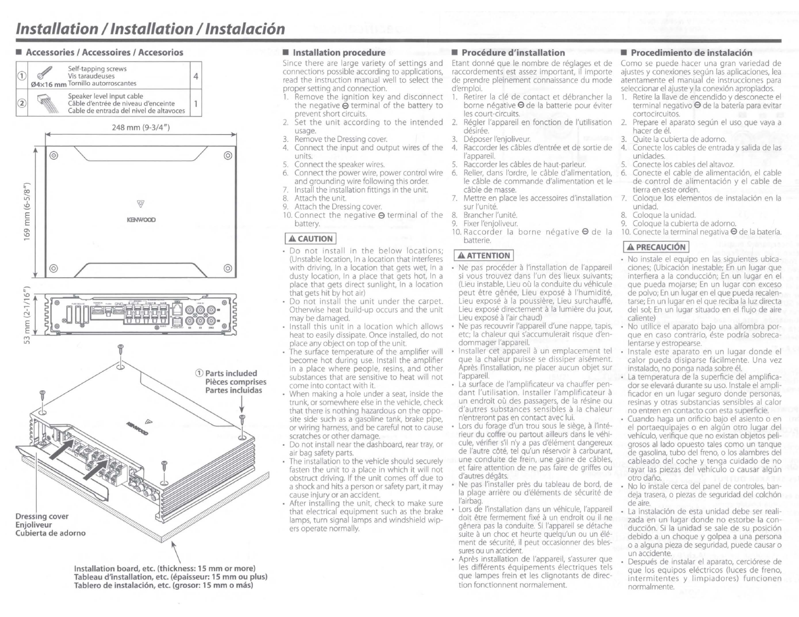
Accessories / Accessoires / Accesorios
G)
✓
Sel
f-ta
pp
ing screws
Vi
stara
ud
eu
ses
04
x16mmTorn
illo
a
ut
orroscantes
@ ' Sp
ea
ker level
inp
ut cable
Cable d'entree
de
niveau d'enceinte
Cable de entrada
del
nivel
de
a
lt
avoces
248
mm
(9-
3/4")
@
"'
'o/
KENWOOD
@ /
Dressing cover
Enjoliveur
Cubierta de adorno
4
1
/ @
" @
G)
Parts included
Pieces comprises
Partes incluidas
i
'
~
Installation board, etc. (thickness:
15
mm
or
more)
Tableau d'installation, etc. (epaisseur:
15
mm
ou
plus)
Tablero
de
instalacion,
etc
. (grosor:
15
mm
o mas)
■
Installation procedure
Since there are large variety
of
settings and
connections possible according
to
applications,
read
the
instruction manual well
to
select the
proper setting and connection.
1.
Remove
the
ignition
key and disconnect
the
negativee terminal
of
the
battery
to
prevent shortcircuits.
2.
Set
the
unit
according
to
the
intended
usage.
3.
Remove the Dressing cover.
4.
Connect
the
input
and
output
wires
of
the
units.
5.
Connect the speaker wires.
6.
Connect the power wire, powercontrol wire
and grounding wirefollowing this order.
7.
Install the installation fittings
in
the unit.
8.
Attach
the
unit.
9.
Attach
the
Dressing cover.
10.
Connect
the
negative
e
terminal
of
the
battery.
IA
CAUTION
I
Do
not
install
in
the
below
locations;
(Unstable location, In a location that interferes
with
driving, In a location that gets wet, In a
dusty location,
In
a place that gets hot, In a
place
that
gets direct sunlight, In a location
thatgets
hit
by
hot
air)
Do
not
install
the
unit
under
the
carpet.
Otherwise heat build-up occurs and the
unit
may bedamaged.
Install this
unit
in a
location
which
allows
heat
to
easily dissipate. Once installed,
do
not
place any object on
top
of
the unit.
The surface temperature
of
the
amplifier will
become
hot
during
use.
Install
the
amplifier
in a place
where
people, resins, and
other
substances that
are
sensitive
to
heat will
not
come
into
contact with it.
When making a hole under a
seat,
inside the
trunk,
or
somewhere
else
in the vehicle, check
that there
is
nothing hazardous
on
the
oppo-
site side such
as
a gasoline tank, brake pipe,
or
wiring
harness,
and be careful
not
to
cause
scratches
or
otherdamage.
Do
not
install near the dashboard,
rear
tray, or
air bag safety parts.
The installation
to
the
vehicle should securely
fasten the
unit
to
a place in which it will
not
obstruct driving.
If
the
unit
comes
off
due
to
a shockand hits a person
or
safety part, it may
cause injuryor an accident.
Aher installing
the
unit, check
to
make sure
that
electrical
equipment
such
as
the brake
lamps, turn signal lamps and windshield wip-
ers
operate normally.
■
Procedure
d'installation
Etant
donne
que le nombre
de
reglages
et
de
raccordements est
assez
important, ii
importe
de prendre pleinement connaissance
du
mode
d'emploi.
1.
Retirer
la
cle
de
contact
et
debrancher
la
borne negative 0 de
la
batterie pour eviter
les
court-circuits.
2.
Regler l'appareil en fonction de !'utilisation
desiree.
3.
Deposer l'enjoliveur.
4.
Raccorder
les
cables d'entree etde sortie
de
l'appareil.
5.
Raccorder
les
cables de haut-parleur.
6.
Relier,
dans l'ordre,
le
cable d'alimentation,
le cable de commande d'alimentation et
le
cable
de
masse.
7.
Mettre en place
les
accessoires d'installation
sur l'unite.
8.
Brancher l'unite.
9.
Fixer
l'enjoliveur.
10.
Raccorder
la
borne
negative
0
de
la
batterie.
IA
ATTENTION
I
Ne
pas
proceder a!'installation de l'appareil
si
vous trouvez dans l'un des lieux suivants;
(Lieu instable, Lieu
ou
la
conduite du vehicule
peut
etre genee, Lieu expose a
l'humid
ite,
Lieu expose a
la
poussiere, Lieu surchauffe,
Lieu expose directement a
la
lumiere
du
jour,
Lieu expose al'air chaud)
Ne
pas
recouvrir l'appareil d'une nappe, tapis,
etc;
la
chaleur qui s'accumulerait risque d'en-
dommagerl'appareil.
Installer cet appareil aun emplacement tel
que
la
chaleur puisse
se
dissiper aisement.
Apres !'installation, ne placer aucun objet sur
l'appareil.
La
surface de l'amplificateur
va
chauffer pen-
dant
!'utilisation. Installer
l'amplificateur
a
un endroit ou des
passagers,
de
la
resine ou
d'autres substances sensibles a
la
chaleur
n'entreront
pas
en contact avec lui.
Lors
du forage d'un trou
sous
le
siege,
al'inte-
rieur du coffre ou partout ailleurs dans
le
vehi-
cule, verifier
s'il
n'y a
pas
d'element dangereux
de l'autre cote, tel qu'un reservoir acarburant,
une conduite de frein, une gaine de cables,
et faire attention de ne
pas
faire
de griffes ou
d'aut
res
degats.
Ne
pas
!'installer pres du tableau de bord, de
la
plage arriere ou d'elements de securite de
l'airbag.
Lors
de !'installation
dans
un
vehicule,
l'appareil
doit
etre fermement fixe aun endroit ou ii ne
genera
pas
la
conduite.
Si
l'appareil
se
detache
suite aun choc et heurte quelqu'un ou un ele-
ment de securite,
ii
peut occasionner
des
bles-
sures
ou
un
accident.
Apres installation
de
l'appareil, s'assurer
que
les
differents
equipements
electriques tels
que
lampes frein
et
les
clignotants de direc-
tion
fonctionnent normalement.
■
Procedimiento
de
instalacion
Como
se
puede
hacer una gran variedad
de
ajustes y conexiones segun
las
aplicaciones,
lea
atentamente el manual de instrucciones para
seleccionarel ajustey
la
conexi6n apropiados.
1.
Retire
la
llave de encendido y desconecte
el
terminal negative 0
de
la
baterfa para evitar
cortocircuitos.
2.
Prepare
el
aparato segun el uso que
vaya
a
hacer de
el.
3.
Quite
la
cubierta
de
adorno.
4.
Conecte
los
cables
de
entrada y salida de
las
unidades.
5.
Conecte
los
cables del altavoz.
6.
Conecte el cable
de
alimentaci6n, el cable
de
control
de alimentaci6n y el cable
de
tierra en este orden.
7.
Coloque los elementos de instalaci6n en
la
unidad.
8.
Coloque
la
unidad.
9.
Coloque
la
cubierta
de
adorno.
10.
Conecte
la
terminal negativa 0 de
la
baterfa.
IA
PRECAUCION
I
No instale
el
equipo en
las
siguientes ubica-
ciones; (Ubicaci6n inestable;
En
un lugar
que
interfiera a
la
conducci6n;
En
un lugar en el
que pueda mojarse;
En
un lugar con exceso
de
polvo;
En
un lugar en
el
que pueda recalen-
tarse;
En
un lugaren
el
quereciba
la
luz directa
del
sol;
En
un lugar situado en el flujo de
aire
caliente)
No utilice
el
aparato bajo una alfombra por-
que en caso contrario, este podrfa sobreca-
lentarsey estropearse.
lnstale este aparato en un
lugar
donde
el
calor pueda disiparse facilmente. Una vez
instalado, no ponga nada sobre
el.
La
temperatura
de
la
superficie del amplifica-
dor
se
elevara durante
su
uso.
lnstale el ampli-
ficador en un lugar seguro
donde
personas,
resinas y otras substancias sensibles al calor
noentren en contacto con esta superficie.
Cuando haga un orificio bajo
el
asiento o en
el
portaequipajes o en algun
otro
lugar del
vehfculo, verifique que no existan objetos peli-
grosos
al
lado opuesto
tales
como un tanque
de gasolina,
tubo
del freno, o los alambres del
cableado del coche y tenga cuidado
de
no
rayar
las
piezas del vehfculo o causar algun
otro dafio.
No
lo instale
cerca
del
panel
de controles, ban-
deja
trasera,
o
piezas
de seguridad del colch6n
deaire.
La
instalaci6n de esta unidad debe ser reali-
zada en un lugar
donde
no estorbe
la
con-
ducci6n.
Si
la
unidad
se
sale
de
su
posici6n
debido a un choque y golpea a una persona
o a alguna pieza de seguridad, puede
causar
o
un accidente.
Despues de instalar el aparato, cerci6rese
de
que
los equipos electricos (luces
de
freno,
intermitentes
y
limpiadores)
funcionen
normalmente.

Connections IRaccordementsIConexiones
A WARNING IRemove the ignition key
and
disconnect
the
negative e terminal
of
the
battery
to
prevent short circuits.
!A AVERTISSEMENT! Retirer la
de
de
contact
et
debranc:her la
borne
negative e
de
la
batterie
pour
eviter les court-circuits.
IA ADVERTENCIA IRetire la llave
de
encendido y desconecte el terminal negativo e
de
la bateria para
evitar
cortocircuitos.
In
a computer-equipped vehicle, when you remove the e terminal
of
the battery, the memory may disappear, or a defect may occur in
the electrical system
of
the vehicle. Consult yourdealer for further details.
Dans
un vehicule equipe d'un ordinateur, lorsque vous retirez
la
borne e de
la
batterie,
la
memoire peut disparaitre ou un defaut peut
se
produire dans le systeme electrique du vehicule. Consultez votre revendeur pour de pl
us
amples details.
En
un vehiculo equipado con ordenador, cuando extrae
el
terminal e de
la
bateria, la memoria puede desaparecer o puede producirse un
defecto en
el
sistema electrico del vehfculo. Consulte a
su
proveedor
para
obtener
mas
detalles.
;;
The product with this logo
is
conformed
to
Hi
-Resolution Audio standard defined by
Japan Audio
Socie
ty.
This
logo
is
used
under license from Japan Audio Society.
It
is
recommended that a car audio system should be configured with all High-Resolution
Audio compatible products from player
to
speaker
to
enjoy
its
high quality sound.
II
est recommande qu'un systeme audio de voiture
doit
etre configure
avec
taus
les
produits
compatibles Audio Haute Resolution de lecteur ahaut-parleur pour apprecier
son son
haute
qualite.
L-----
-
--
- -
Se
recomienda que
el
Sistema
de audio del cache
este
configu-
I
AWARNINGI
Particular attention must be given to making
good electrical contact at the amplifier-out-
put and speaker terminals.
raccorde ne touche
la
carrosserie de
la
voiture.
Ne
pas
retirer
les
capuchons des
cables au connecteurs non raccordes afin
d'eviter tout courtcircuit.
■
Power wire and speaker wire connection I
AFTER
MARKET
I
■
Raccordement d'un cable
de
l'alimentation
et
d'enc:einte
HEAD
UNIT
rado con todos los productos compatibles con
el
audio de alta
resoluci6n, desde
el
reproductor
hasta
las
altavoces,
para
disfrutar
su
alta calidad de sonido.
Poor or loose connections
can
cause
spark-
ing or burning at the terminals because
of
the very high power that the amplifier
can
deliver.
IA CAUTION I
If
sound
is
nor
output
normally,
imme
-
diately
turn
power
off
and
che
ck
connections.
Be
sure
to turn the power offbefore chang-
ing the setting
of
any switch.
If
the fuse blows, check wires for shorts,
then replace the
fuse
with one
of
the
same
rating.
Check that no unconnected wires or con-
nectors
are
touching the
car
body. Do not
remove caps from unconnected wires or
connectors to prevent short circuits.
Connect the
speaker
wires to appropriate
speaker
connectors
separately.
Sharing
the
negative wire
of
the
speaker
or grounding
speaker
wires to the metal body
of
the
car
can
cause
this unit to
fail.
After installation, check
that
the
brake
lamps, rurn signal lamps and windshield
wipers work properl
y.
IA AVERTISSEMENT I
Veillez ace que
le
contact
electrique ala
sortie de l'amplificateur
et
aux prises des
enceintes soit bien etabli.
Un
mauvais branchement ou un branche-
ment lache peutcauser
des
etincelles ou un
rechauffement
des
prises
du
fait de
la
tres
grande pui
ssance
de l'amplificateur.
IA ATTENTION I
En
cas
d'anomalie, mettre immediatement
l'appareil hors tension et verifier taus
les
raccordements.
Veiller a
mettre
l'appareil
hors
ten-
sion avant de changer
la
position
des
commutateurs.
Si
le
fusible
saute,
verifier
si
les
cables ne
sont
pas court-circuites,
et
remp
lacer
le fusible
pa
r
un
autre fusible de meme
capacite nominale.
Verifier qu'aucun cable ou connecteur non
Raccorde
r separement
les
cables de haut-
parleur aux connecteurs de haut-parleur
appropries.
La
mise en commun du cable
negatif
d'un
haut-parleur
ou
des fils de
masse des haut-parleurs a
la
carrosserie
metallique de
la
voiture pourrait rendre
l'appareil inoperant.
Apres
!'installation, verifier que
les
voyants
de frein,
les
clignotants et
les
essuie-glace
fonctionnent correctement.
IA ADVERTENCIA I
Debe ponerse especial atenci6n
para
que
se
haga
un buen contacto electrico en
la
salida
del amplificador y en
los
terminales de los
altavoces.
Las
conexiones mal hechas o
las
conexiones
fiojas pueden causar chispas o quemaduras
en
los
terminales debido a
la
potencia muy
alta que puede suministrar
el
amplificador.
IA PRECAUCl6N I
Si
el
sonido no
sale
normalmente, desco-
necte inmediatamente
la
alimentaci6n y
compruebe
las
conexiones.
No
se
olvide de desconectar
la
alimenta-
ci6n antes de cambiar
el
ajuste de cual-
quier conmutador.
Si
el
fusible
se
quema, compruebe que no
haya
un cortocircuito
en
los
cables,
luego
cambie
el
fusible
por
uno
que tenga el
mismo amperaje.
Veriflque
que
ninguno
de los cables o
conectores
que
estan sin
conectar
se
encuentren tocando
la
carrocer
ia
del auto-
m6vil. No retire
las
tapas de los cabl
es
o
conectores que est.in
sin
conectar
para
evi-
tar de que
se
produzcan cortocircuitos.
Conecte
los cables del al
tavoz
a los
conectores adecuados del altavoz separa-
damente.
La
puesta
en
contacto de termi-
nales
de altavoces distintos, o
la
conexi6n
como toma de tierra de
los
termin
ales
del
altavoz
al
coche del autom6vil, pueden
causar
danos alaunidad.
Despues
de
la
instalaci6n, compruebe que
las
lamparas del freno,
luces
de
des
tello y
limpiaparabri
sas
funcionar correctamente.
■
Conexi6n del cable de alimentaci6n y del altavoz
:Ji
Power control wire;
for
"RCA
INPUT connection"
Cable de commande
de
l'alimentation; pour «Raccordement
RCA
INPUT
»
Cable de control de alimentaci6n; para "Conexi6n
RCA
INPUT"
't
¢:,
Battery wi
re
Cable de
la
batterie-.
Cable de
la
bateria
Protective fuse
Fus
ible de protection
Fusible de protecci6n
~
IAWARNINGI
To
prevent fire caused by a short in the
wiring, connect a fusible link or breaker
nearby the battery's positive terminal.
IA AVERTISSEMENT I
Pour
eviter tout incendie
dO
aun court-cir-
cuit, inserer un fusible ou un coupecircuit
aproximite de
la
borne de
la
batterie.
IA ADVERTENCIA I
Para
evitar incendios producidos
par
cor-
tocircuitos en el cableado,
conecte
un
fusible o cortacircuito entre la bateria y
las
terminales de
la
bateria.
Battery
Batterie
Bateria
i
Ground wire
Cable
de
masse
Cable
de
masa
Subwoofer
(L
+
R)
O~~
Haut-parleur
d'extreme grave
e e (G+
o)
Altavoz de
subgraves (l+D)
Lead terminal
Cosse
pour cable
Terminal de cable
~
11
Stereo / Stereo / Estereof6nicas
L::::
0
~
~
A.
ch
~~~che
8~~
Izquierdo
e ~
~A
.
ch
~i
(o~:
'---
0
~
~
Derecho
e~~
'===;!:=~======O~~
B.ch
~ =
====
:~=+
r } .
ch
Bridged /
Pont/
Puenteada
l_
J::
™
:~~A
.
ch
Left
Gauche
Izquierdo
Right
Droit
Derecho
o usFT e
e.....,.
o
sue
o Subwoofer
(L
+
R)
~
~
Haut-parleur
ill
0~
, 0 d'extreme grave
~e~
(G+D)
0
...,..;r--
8 Altavoz de
,;,,,,;;;;;;,,,,;....,;;;;;;,
9
.,iu
~
subgraves (l+D)
~~~B
.
ch

Connections IRaccordementsIConexiones
■
RCA
INPUT connection
■
Raccordement RCA INPUT
■
Conexion
RCA
INPUT
Powercontrol wire
AmRMARKET
HEADUNff
Cable de commande
de
l'allmentatio~
Cable
de
control de alimentac:ion
i
¢,
■
Speakerlevel
input
connections
■
Raccordement au niveau
haut-parleur
■
Conexion
para
entrada
de
altavoz
A
INOTEI
FACTORY
INSTAUED
HEAD
UNIT
,,.
l•JI
1111111:l
I ~Jiil,•
ill'
I
ii
dd~
lo
l.,01
r,
HCA
c.ibl
input
l
ads
.1110
t~e
sneake, level
'IPUt
te
1
1111nals
11nul
anrotJ~ly,
fo, t
in~
mav rau1,0
malfunc11011
r 1;il'1a7P
I
REMARQUE
I
I
11111
.-RCA
cable
Cable
RCA
cable
RCA
~::::a----•..-~
Parts
Included
11
Pieces
comprises
Partes
lnduidas
.,
-
lf'
! a I r
11<Jt•1
1j1•,
Lat..ll·, >
co11d
,JC1eu1
s ,
l,1
fu1; .,~~ l,llls s Iv
~ur
II
p•JlH
c.j
l ,I,
HCA
el
a,.,,
nr
'
d,enrree de
ha111
p.,rl,..ur
c~r
l,1
[
.p
1e,I
r
;;querwl
1
'ell
l'ndon111Mqe
vi/
J,
1
11
. lur1 t'1onni1r
cable
color
of
the
connector
I
Couleur
de
dible
du
connecteur
/
Color
del
cabledel
conector
!
NOTA
:
N
Clllf'Ct•
Sln';Jlt~•·1f',Jm('rl
t'
cab1~s
nr
conduuo
r
P.s
il
las
toma~ d(.'
•qtrart.,
fie
r.ahlc:,
fl(I\
o a
loi
I"'
mrnales
dl'
l'll
ll
ad~
de
.ilr.wo cs
po1q•H'
po.J1
f~
111oc
luci•i•'
c;nJ
"""
'
la.
...
,
1.
J
~,
l
}il
Bi
~I
.!1
tfu
A channel Left
Acanal Gauche
Acanal Izquierdo
Achannel Right
Acanal Droll
Acanal Derecho
Bchannel Left
Bcanal Gauche
B
tilnal
Izquierdo
Bchannel Right
B
c.1nal
Droll
Bcanal Derecho
e While/ Blanc / Blanco
9 White-Black/ Blanc-Noir/ Blanco·Negro
@
Gray
I
G11s
/
Gr
is
9 Gray
Black/
Gris-Nair / Gris-Negro
@ Green / Vert/ Verde
e Gleen Black/Vert·Notr/Verde-Negro
® Purple / Violet/ Purpura
0 Purple-Black / Violet-Norr/ Purpura Negro
System
examples
I
Exemple
de
configuration
I
Ejemplos
de/
sistema
■
5-channel system (1)
■
Systeme svoles (1)
■
Sistema
de
5 canal
es
(1) Front
left
speaker
Haut-parleuravant gauche
Altavoz
delantero
izquierdo
HEAD
UNIT
Front
right
speaker
Haut-parleur avaht
droll
Altavoz
delantero
derecho
Rear
left
speaker
Haut-parleur arriere
gauche
Altavoztrasero
Izquierdo
OD
CUJ
Rear
right
speaker
Haut•parleur arrii!re
droit
Altavoztrasero derecho
,_-,,i
~
-r--" .......
nF"i'
HFIF
[]Ff,-
HPf.-
D
R.rr..
0 Subwoofer
(L+RJ
Haut
-
parleur
d'extri!me
grave (G+D)
Altavoz
de
subgraves
ll+Dl
Selectllmil
when
there
Is
connection
to
the
SUB
input
SelectlonnezmIDlorsqu'II
n'y
a aucuneconnexion al'entree
SUB.
Seleccionell!!liJcuando haya coneirl6n a la
entrada
SUB.
■
5-channel system (2)
■
Systeme5 voies (2)
■
Sistema
de
5 canales
(21
Front
left
speaker
Haut-parleuravantgauche
Altavoz
delantero
Izquierdo
HEADUNff
Front
right
speaker
Haut-parleur
avant
droit
Altavoz
delantero
derecho
Rear
left
speaker
Haut-parleur arriere gauche
Alt:avoz trasero
Izquierdo
Rear
right
speaker
Haut-
parleur
arriere
drolt
Altavoz trasero derecho
Subwoofer (L+R)
Haut-parleur d'extremegrave(G+D)
Altavoz
de
subgraves(l+D)
Select
am
when
there
Is
no
connection
to
the
SUB
Input
.
SUB
output
signal
Is
created
by
this
unit.
Selectlonnez
mm
lorsqu'II
n'y
a aucune connexional'entree
SUB.
L~
signal
de
sortie
SUB
est
cree
par
cet
appareJI.
Selecclone
am
cuando
no
haya conexi6na la entrada SUB.
La
serial
de
salida
SUB
se crea
medlante
esta
unldad
.

Controls I Contra/es IContra/es
The
unit
Is
a 5-
channel
amplifier
Incorporating
2
stereo
amplifi-
ers
and
1
monaural
ampliner
in a
single
body. The
stereo
ampllner
on
one
side
is
called
amplifier
A,
while
the
one
on
the
other
side
is
amplifier
B.
The
monaural
amplifi-
er
Is
called
the
amplifier
SUB
. This
unit
Is
compat
ible
with
a large va-
riety
of
systems by
combining
the
switches
and functions described
In the following.
, ,
Fuse
(30 Ax3)
j
NOTE
j
I[
\'VU
cJn't
tmrt
rh,•
r«J•e<l
ColP,lClly
:J:~'/J(
16r'
dP~lr;:"
Pl~
'1Sllll
y
llJI
2 Battery terminal
(POWER
IN
BATT.)
l
Power
control terminal
IP.CON)
1n
r•."llr.
thl'
uni•
ON'
)IT
,~
Ground
terminal
(GNDJ
s•
SPEAKER
OUTPUT
terminals
(A.ch/8.c.hJ
•
Stereo
connettions:
Wf1nn
yoI
w•
.h
to
I
;e
1t1"
nit a
,I
{f•f,..., 1 ,,;n,pliti(•f .t·
')
1nn1Xl11JI
:
;i,.=,.
IJC,t:ti
The
'.lpei1;..e,~
to
b•
..
COi .
ne-;tt"'tl
\h011ld
I
wu
"
l111rx::i:w,.=-
of
2
[}
u1
oreate1.
When
mu
ltlph~
,t1l:'rJ~
t•,s
ate
u.>
tie
connP.Cied.
er~1Jrr
:ha,
tw
"11nh1n?t1
impe1.lann
::.
0
ur
1r,•,11erfmP.,,
1d1il111,:I
, Bridged
connectlon.s
;
Wl,t.11
,,
,u
w1
t,
ti::
~
..
~
h.-
Unit
r a
I
,qt
,u
tp111
amplllh
r.
b111l
l'"I
cor
nec11on•
art u;ed
(Maise
mnec1,11n'
•>
11-..-,
·FT
tw1nel $
md
lhe
HI
,11
h,J11t,•I
9 ,Pf ~Kl F IPUT I
rm
"\,
11
,., H
I".,,
',,
hl
tlf1I11'C1Prl
,ho,ild h,,ve
J•
,rnpc
far<r.-
of "
,,
1r~.tc-r.
When
n ·
lt,1>1~
s[l\'afe•s
die
I ,
l,
cnrr
tgd
.'n•-.t.HP
that the
.r.om
blried ,.,,p,.danc
I•
d
Oo
-.irwte1
~.
SPEAKER
OUTPUT
terminals
(
SUBJ
1\1
tltl•
.11111
"'
eu1
lfl<"dfe,
1111
111,imunt
irni••
..
Jjl
)(,...
or'}
(,hr11
,
CL
1
n
111.:.ll
:,~~dkt
,~
wit'".
'."'
ohrn
or
Iuglier
1111pedance
[O
rbe1e
rerminul_
1
SP
LEVELINPUTterminal
1'
L<
µL,
tJll
tht
A(T)RY
IN'
IAI I
LO
l
A1
l•NI,
<.1r
'·0
v,1
ca11
t,
.. mpu1
:h~
11cweI
11
tull\
ill
on and
CJft
di.
!he
urnl
(l~lt(IS
ll'P"'
s,grr~I fSIGNI\L ~~N"IN(_,
"lH!N
ONl
Th,·
rt'fnre
It
ir,
-•1t
n ,
--
es:~uv
r,
'""On
t
lhe
pov,,t-1r
(,,n!rc..,.
v-111:
".['
REMOTE
terminal
(SUB!
(for separately available part
KCA-RC01A)
nu~
wrrr,nal
,i
II exclu1iw 1
1,rm1na!
frn t
Jlll
1!11
t > J
1Jui::t
t~
volut
11
of
tt1t
SUB
IJullJUL
~
LINE
IN
terminal (A.ch/
B.ch
/
SUBI
IO
IINPUT
SENSITIVITY
control
(A.ch/B,ch/SUBJ
et
hi
conrro
1r
HdInrJ
to
ll,c
pt
-oulpul
vel
ot
1,,
EAll
lJNII
·JnnPr
fp,·j wnn
lhl,
11111
INOTEI
·or
rhe
pre output
11:vt
'',
re-
er
Lil
11,~
~p1cuflc.,111on1·
In
n,e
r11struc11on
111,u
,ual
nt
llrt·
>if-Ar>
UNIT
11
INPUT
SELECTOR
switch
·I
ti,,~
.Vile ,ice
--irt.liny
tu
th,
wn
ne
rr
in
Wllh
11
"·
Ullll
• A Bposition:
el••<I ' .vh, n "'-'''-' I
1,0
onr
C n ,n to the
;tJ
Inp1,1
~LIB
oul
pu1
~,qnai , u
ate
I01'
11111
uni
•
SUB
position:
t;elf
,·t
SUB
yhpr1
lht
1
r1.;
ts
:inn
_lion
t<>
1hf.
.,ur:;
1nuut.
'w
BASS
BOOST
LEVEL
control
(SUBJ
<p1
th,
km
Ir
4u,
, I
wt
tu b,
• ~rrll)l.:!H Jl• I
·u
LPF
FREQUENCY
control
(SUB)
Thi\
□
rt
I
oUJlJ
,.,,~
1,equt.'th
bar
Jutp~t
r,c
,.
•r
••lit
,~
FILTER
5wltch
IA.ch
/
B.ch)
1
h1,
wild'
"II
,w
til'
·r
nq
f
t,,
,f"E',ik,-
CtJlf'
_1ndl;
•
HPF
(High-Pass
Filter) position:
I
h~
f1l1<!1
<Julpu•
ti
,,
·_JPi.J
or t,lqhe
l:Pquenue:.
tliJ11
II i
f1eq1J~11,y
,et
with
1he
I Ir
tG
li.N(Y"control
•
OFF
position:
Th,
entire
•1ar
LJ11111lll1,
ulpuI
"1111'1
cut
~lter1119
~~
HPF
FREQUENCY
control
(A.ch
/
8.chJ
h1~
u~r)lr•)I id, 1 r n~
r,
1ud
K)'
I
,nd
uurr
,,
Imm
ru~
111
ll•
Power indicator
Whcr•
rt1e
powe1 "1ur11rd 011 tl1t>
Povve:r
rnd,
.Hor liqt
,r
Cet
appareil
est
un
amplificateur a5
canaux
rassemblant
dans
un
meme
boitler 2 amplllicateurs
stereo
et
un
ampllflcateur monaural. L'amplifi-
cateur stereo d'
un
cote
est
appelt!
amplilicateur
A,
tandis que
celul
de
l'autre cote
est
deslgne
par la lenre
B.
L'ampliflcateur monaur.il
e.s1
consldere
comme
ampllficateut
SUB.
Cet apparel!
e.st
compatible
ave<
dlverses configurations de chaine,
simplement
en
selectlonnant
les
positions
des
commutateurs et lei
fonctions
comme
lndiqued
-a
pres
.
J
Fusible
(30
Ax
3)
I
REMARQUE
I
V•JU
n,
tlOUlll'l
pa~
de
luslble
J,
.-ahbre .ioequat Jan·
I,
ccrr1111ert£>
etc
-ontacter vo
,e
Jqent
KENWOC'f'
il
Borne
POWER
IN
BATT.
(alimenta-
tion)
_!)
Borne
P.CON
(fit de
command&
d'allmentation)
,..,,mm;,n
dt
l'unit<?0N
·o;:r
◄
Borne
GNO
(masse)
5l
Bornes
SPEAKER
OUTPUT
(A.ch/B.ch)
•
Connexions
stereo:
Pow
u111t.
• I
at1r
,,t!il comme
a1T1):Ji<fl
L,1Leu1
•;rerro
des
connecuons ,rc!Jt!t
doM,nt ~fr,•
u11h1ees
Les
hJul
p,1rleur•
,l
co
nric
.:ter
<Jo
1ven1
uvoir Line
impt'
dant~ de 2ohms
011
supcr,uwe
Lo,<,qu1·
plusif'urr
h1tUl
·par/t1
lJ(.$
dolvent fltrt
.or1neni>;,
•.·a,1t1
rf'1
que nmpedanc1
~mh,nee
SOIi
de
ohm1
,,.,
11.11,r,•11t!un
r1ur<f'i,1qu,·1,111<1I
,
Connexions
en
pont,
i>
)W
I
1111,
{ICll'
1,·
I
dlJfr.lr""
C.OFT\llll
atnplll:
.,11,,u,
a haurr
µu,~n,e1h.
Wlti'
I.Jes
co11ricc1,on•,
en
pom
do,vent •r,
•Ir#.
(I'~,,.
I~,
rcnne,,ors "
t,ornc
,,•l'AH.R
)l,fPtJI
du
canal
JJL
,,,,
ii
Ef
I (ll e
de
~a11JI
tlrr•t
(Ai(HT) 9
le-
I
JUI
pJrll'Uh
d •
,.,,-,r
L·r
t.:Jo1vcnt
avoir
t,tn
11ru)Pda.nre
r1e
4
ohm:
:.1u
supn
r,Q,u~.
LorsqLte
plus1e
ur1
,,Jut
parlew
Jo111<::nt
l-trc·
Cllf1ru
ct,•,;,
\'ass,
11,.,r
q<1e
ltrn·
1:
Jar
t
--•n,t:,1nP•
JII
dr
1
<'lt1ms
111
,UJ.Jt.Jf!t·
lll
1'
6
Bornes
SPEAKER
OUTPUT
(SUB)
et
~PP
11~,1
~t
,,
r
~on~1,
po"r
fon,·rron·
11~r
-JV1
ll1t:
m~
_..J,:1n
:,·:
,_hc:Hf)r-1
,Je-
1hrm tout
IM,Jl-p.irlc>ur
cfort
1111,pe
..
1 t
f.qalp
"JV
.Jp
•·
UI
~
f)(
lffl.
p::-ut
•tie-
r,ran1
-t
r
<-
J'
(.L,
prhb
7) Borne
SP
LEVEL
INPUT (niveau
haut-parleur)
Lo
t1u1
sar-..._
;I
J.
,rln~
Pw-.:rmurT
J'"'
rACIOPY
IN:
\ll.LD
fllAD
UNIT
nP
dail
pdS
de'-1,as1e1
50 W ·a11memat,an
es1
Rt1vee
e1
Jesact1,·ee
lorsqt1e
l'apparc11
d~'>Xte It: s,grtal
d'•intt~
/SIGNAL
SEN
;11,G
TURN
ON)
.~, fl(lLllQllOJ
,I
n't'\1
,.JS
!'ls.Ill•
J,,
en
,-
t•
1~
table
Je
(
J'lHTlUfl(.k
.Jl
1 Jli111t
1liJliOrt
iJ
Borne
REMOTE
(SUB)
(pour
la
pi~ce
KCA·RC01A
dispo•
nible separement)
(t"t!c
t..>vint
i,11
:i.
uih11,.•11wn1 j
Unt~
tek :om111J
11t
li:a
p-Jur
tP(Jlf!'r
It
vnlumi:,
dP
1a
~rtle
.:.,
,B
v
Borne
LINE
IN
(entree
de
lrgne)
(A.ch
I
B.ch
/
SUB)
i•
•
Commande
INPUT
SENSI
•
TIVITY (senslblllte d'
entreeJ
(A.ch/B.ch/SUB)
f~lt
11 1
ttt>
\_\lfllrn,
ndt~
,µJ.-u
1.,
ol\11-.,H
d,·
r,rr'
'ICrllf> Jp
IJ
I
l(AD
UNIT
t,,~nd,~
cer
.1mphhca1eur.
I
REMARQUE
I
rt
rr•n:
J
IJ
!!-f'l
t
IOI
<
,pcc1h(
JIIon~•
&:~tvl
J
}~~rl[~~H,
i)
(~1Hlil
El
1§1
l;l!m
la!l3
€lmJ
a Isl
du
mJnue:
d,
~
In1tn.
··,ns
rl•
1-1
f-'EA'•
UNIT
,i prop<~ h, niveaude
fJIF
\("'11P
(
11
1Commutateur
INPUT
SELECTOR
(st!lecteur
d'entree)
Rct1ll.
:,;
, m
,rnuto'~"'
en
fonn,nn
rle
la
c:,nnexoon
v,,
t't
•f'f>dte,I
•
Position
A8:
',de,11""' A B, IOrl(lu'il rl'y a
,11Jt:tme
conne,1or, rentr,l,e
SUB.
Le
_ignJI
cJe
',(Jflle
SUB
e,;1
cre-1
par
ce1
ar..,pa,c,I
•
Position
SUB;
S...'~tliOnl".;.c
,c1a
1,
•I'
II
n'y"
"'"
,,.,
..
l<Yll
.,,
~
f'!'f1lll
~
<.JI'.
(
1;
Commande
BASS
BOOST
LEVEL
(SUB)
~"!JI~
le
nivt
,
d!.'
I.lo~.
e lrequen,:e
ll<'v,mt 01"
Dnt
r
:f
,e
Il
l)
Commande
LPF
FREQUENCY
(SUBI
Lelle ·onunar
.Jr
ne11nL
de ,eyler
la
b,
ndr:
dr
ltequenc~
on
1rt11. de
1•1
apparel!
lt
•l Commutateur
FILTER
(A.ch/B.ch)
Ce
~omrnutateur
est
de
nnes
au
filt1aqe
d••s
s,gn,
'"
de
smt1P
des
hallt-rwleur
•
Position
HPF
(Flltre
passe-haut):
Lt'
filt1e
la1s1P
pa,wr
I~
lrcqur.--
.<'
,upe-
~':i~~~I~~•~~'.;
;~~
~'rci~tNc~:11uver,
•
Position
OFF
:
:;
:;:~tu~a1~~
~~;~,~~1;.e~:,~:
i.:~~~::
t!r
~ortle.
!lJ,-
Commande
HPF
FREQUENCY
(A.ch/B.ch)
(
ellt'
c~mrr
ir1dl
rermet
le lf'4le1
Id
lMndc
le ltf'1lJt'f1
t'
~II
.nil
1
..
"'!
lpfllt'II
11~
lndicateur d
'a
limentation
Lcr"\CIIJI-"
l\lllm,~r:tat1 fl I
ch
II
Vt"'.:'.
1
'in,.I,
..
otti•J•
c.fahrnet1tritt<
~1
'Uh
m111
La
unidad
es
un
ampliflcador
de
S
canales que incorpora 2 ampllfl-
cadores
estt!reo
y
un
ampllficador
monocanal, todo
en
uno.
El
ampli-
ficador estereo de
un
lado
se
llama
amplificador
A.
mientras que
el
del
otro lado
es
el ampllflcador
B.
El
ampllflcador monocanal
se
llama
amplificador
SUB.
Comblmindo
lo.s
conmutadores y
las
fundones
de.s-
crltas a continuacion,
esta
unidad
amplificadora
es
compatible
con
una
arnplla
gama
de
slstemas,
(1 Fusible
(30
A x
3J
I
NOTA
I
~i
r ru•.J•· encontrJ1 d fiwble de
la
c,1r,Kld
,I
esr,eciflcauJ
t'I\
su
~lrn"
cen etc.,
-onsulte
su d1s•t1buli:lt11
KENWOOD
l'2l
Terminal
POWER
IN
BATT
.
(alimentaci6n)
•! Terminal P.
CON
!control
de
corrfenteJ
tonJrol,
-1
')n, x,,in/•fr.sccme"c,'
1,
,
la
.111ldod
14, Terrninal
GND
(tierra)
(!. Terminates
SPEAKER
OUTPUT
(A
,
ch/B,c.h)
•
ConeMlones
estereof6nlcas:
CUJr
,Jo
de el' us.ir
Id
un1dad
como
un ampltfrGJdor estercofon1co
!ISied
d~beril utllrl,H
co,w,c,on,~
e5teri'of6n1
as.
Los
allal/0Cr5 •
co11eciar
deberan
Tener
una impeu.md.1
t.le
2obrnio ,
::re:
il~t~;~~~'.~~a::e~~~;:'-;~~
~~~
a 1mpedanc
,a
,.omtunJrJa
,e,1
e I
olimtoi , n,~yor
f>dt,1
c-,da
carr,tl
•
ConeMlones
en
puente:
r u,mdu
div.,....,
uc;.;ii
ll
\Jnl•
!.:i
J ;imu ,
amollflcador
dp
alta
p, terir
io
u
•,tP<
I
®
J1-1
•·ra
,1111,ar
Cl'.mf«on~
en
pctL•ntt:
Hagd
l,is
,;u11••.llio11es
a
,,.,,.
1et~1lna
,,
J,.
JildJ
de
alt,lVO(eS
(S
PtAKl:fl
OUTPUT)
d•
Im
c.analEI
lzqule100
(LEm ® y oerecho
{RIGHT
e .o;
Jltavou
, .one'1,l' Jebe1Jri rn~,
11
111.,,J,1r
··,.de 4
ohmoos
c
Nyor
LU.ttllir·
Vily
I
~a1
m ,,
ip'e
all
v\J(i'\
~segtJrP ede
qu~
Id
lmpedd
Ck!
cJrr:blnaJil
se;,
de
,J
ohmlos o
rnavrn
J'
Terminales
SPEAKER
OUTPUT
(SUB)
C...,
o
ste
apwtv , ~l)lJ JllJv<.•.t: con
una
1m~,edanc1a
fr1in1111a
de;
ohn110...,
conectc
altavoces
cor>
Jnil
in1pedi1nna
ar,
otim,01
o
mas
a.,.;to-
•.-rrn,niJles
·1
Terminat
SP
LEVEL
INPUT
(entrada
di!
altavoz)
E.I
0
AC1ORY
IN~TALLEC
HEAC.
UNIT
,1el.,,A terw1 una potenr,~
d~
:.alida
,nA.,md
J"IO
~UµErio,
I
)0
w I.
.3
dl1-
men1,1r:16n
;e
.-,;c,,.mde
y
apaqa
cor,-
ro,rne
la
umdad
ciell.'Clic
una
x>r'ldl
tfo
entradd
ISIGIIJAl
SENSII\JG
TURN
ON),
Por
lo
rariro
no
e\
11ecesa1
lo conecrar
el
:abte
de control d,.
al11·.1:ntil1
ion.
a'
Terminal
REMOTE
(SUB)
(para
la
pleza
KCA-RC01A
dlsponl•
blepor
separadoJ
Este
[erm,nal
e1
un
term,na\
cxclus1vo
para
1.1n
(0ntrolador p,lrJ dlu,t,11 el
voturnen tit'
1<1
;J\id;
~IJ8
! ITerminal
LINE
IN
(entrada de
lineal (A.ch/B.ch/SUB)
!9
Control INPUT
SENSITTVITY
(senslbllldad
de
entradal
(A.ch/8.ch/SUBJ
~/~;~\
~~1~,~~~:;~r
f;,!'~~~o
uci;
r
)11,
r,1dt
~
i l~
irnplU1
1td1:,1
j
NOTA
I
@
@

Troubleshooting Guide
What
might
appear
to
be a malfunction in
your
unit
may
just
be
the
result
of
slightmisoperation
or
miswiring.
Beforecallingservice, firstcheck the following table
for
possibleproblems.
PROBLEM
POSSIBLE
CAUSE
SOLUTION
No
sound. •
Input
(or output) cables are disconnected. •Connect
the
input
(or output) cables.
(No sound from
one
•Protection circuit may
be
activated. •Check connections by referring
to
"Protection
side.} function''.
(Blown fuse.) •Volume
is
too
high. •Replace
the
fuse and use lowervolume.
•The speaker cord
is
shorted. •After check
the
speaker cord and fixing
the
cause
of
the
short, replace
the
fuse.
The
output
level
is
too
•The
input
sensitivity adjusting control
is
not
•Adjust
the
control correctly referring
to
"Con-
small
(or
too
larae). set
to
the
correct oosition.
trols''.
The
sound
quality
is
•
The
speakers
wire
are
connected
with
•Connect
them
properly checking the @/ 0
bad.
wrong
@/ 0 polarity.
of
the
terminals and wires well.
(The sound
is
•A speaker wire
is
pinched by a screw in the •Connect
the
speaker wire again
so
that
it
is
distorted.) car body.
not
pinched by anything.
•The switches may be set improperly. •Set switches properly by referring
to
"Con-
trols''.
Guidede
depannage
Ce
qui
peut
apparaitre
comme
un
mauvais fonctionnement
de
votre
appareil
n'est
peut
-
etre
que
le
resultat
d'unemauvaiseoperation
ou
d'unemauvaiseconnexion.
Avant
d'appelerun centre
de
service, verifiez
d'abord
dans le
tableau
suivant/es problemespossibles.
PROBLEME
CAUSE
POSSIBLE
SOLUTION
Absence
de
sons. •
Les
cables
d'entree
(ou
de
sortie)
sont
•Brancher
les
cables d'entree (ou de sortie).
(Pas
de
son
d'un
cote) debranches.
(Fusiblegrille) •Le
circuit
de
protection
peut
etre
•Verifier les raccordements en
se
reportant au
actionne. paragraphe «Fonction
de
protection».
•
Le
volume est
trop
fort. •Remplacez le fusible
et
utilisez
un
niveau
de
volume plus faible.
•
Les
fils
de
raccordement d'enceinte sont •Apres avoir verifie le cable d'enceinte
et
repare
en court-circuit.
la
cause
du
court-circuit, remolacez le fusible.
Niveau
de
sortie
trop
•
La
commande
de
reglage
de
la
sensibilite
d'en-
•
Faire
le reglage correctement en
se
reportant
faible
(ou
trop
fort).
tree
n'est
pas
amenee
sur
la
bonne
position.
aux indications donnees en
«Contr61es».
La
qualite
sonore est •
Les
cables
de
haut-parleur
ont
ete raccor- •Raccorder correctement en respectant
les
indi-
mauvaise. des en inversant
la
polarite @/ 0 . cations @
et
0 des bornes
et
des cables.
(Le son estdistordu.) •Un cable
de
haut-parleur
est
pince
par •Rebrancher le cable
de
haut-parleur en evitant
une
vis
dans le chassis
de
la
voiture.
tout
pincement
•
Les
commutateurs ne sont peut-etre
pas
•
Positionner
les
commutateurs
en
tenant
positionnes
comme
ii convient.
compte
des
indications
fournies aux para-
qraphes
«Contr61es».

Specifications
Specificationssubject
to
changewithoutnotice.
Audiosection
Rated
power output
(+B==
14.4
V)
Stereo
(4
0)
+
SUB
(4
0)
..................................
50Wx4
(20
Hz-20
kHz,::;;
1.0%
THD)+
300
W
(20
Hz-200
Hz,
s;
1.0%
THD)
Stereo
(2
0)
+
SUB
(2
0)
.......
75
Wx4
(1
kHz,
s;
1.0%
THD)
+
500
W
(100
Hz,
s;
1.0%
THD)
Bridged
(4
0)
+
SUB
(4
0)
....
150
Wx
2
(1
kHz,
s;
1.0%
THD)
+
300
W
(20
Hz-200
Hz,
s;
1.0%
THD)
Speaker
impedance
............................
.4 0
(2
0 to 80 allowable)
(Bridged connection: 40 to 80 allowable)
Frequency
response
(+O,
-3
dB)
..............................
20
Hz-50
kHz
(+O,
-3
dB)
.................
20
Hz-200
Hz
(SUB)
Inputsensitivity
(RCA)
............................................................
0.2
V-5.0V
Signal
to
noise
ratio
.........................................................................
100
dB
Input impedance
................................................................................
10
kO
Specifications
Les specifications
sont
sujettes
achangements sans
notification.
Section
audio
Puissance
de sortie nominale
(+B
=
14,4
V)
Stereo
(4
0)
+
SUB
(4
0)
...................................
.50Wx4
(20
Hz-20
kHz,
s;
1,0%
THD)+
300
W
(20
Hz-200
Hz,
s;
1,0%
THD)
Stereo
(2
0)
+
SUB
(2
0)
.......
75
Wx4
(1
kHz,..;;
1,0%
THD)
+
500
W
(100
Hz,
s;
1,0%
THD)
Pont
(4
0)
+
SUB
(4
0)
........
150
Wx
2
(1
kHz,
s;
1,0%
THD)
+
300
W
(20
Hz-200
Hz,
s;
1,0%
THD)
Impedance d'enceinte
......................
..4
0
(2
0 a8 0
admissible)
(Connexions
en
pont: 40 a80 admissible)
Reponse
en
frequence
(+O,
-3
dB)
.........................
20
Hz-50
kHz
(+O,
-3
dB)
...........
20
Hz-
200
Hz
(SUB)
Sensibilite d'entree
(RCA)
...................................................
0,2
v-s,o
V
Taux
de signal/bruit
.......................................................................
l
00
dB
Impedance d'entree
..........................................................................
1o
kO
Especificaciones
Las
especificaciones
se
encuentran sujetas a cambios
sinprevioaviso.
Seccion
de
audio
Salida
de potencia nominal
(+B
==
14,4
V)
Estereofonicas
(4
0)
+
SUB
(4
0)
..........................................
50
Wx4
(20
Hz-20
kHz,
s;
1,0%
de distorsion armonica total)+
300
W
(20
Hz-200
Hz,
s;
1,0%
de distorsion armonica total)
Estereof6nicas
(2
0)
+
SUB
(2
0)
..........................................
75
Wx4
(1
kHz,
s;
1,0%
de distorsion armonica total)+
500
W
(100
Hz,
s;
1,0%
de distorsion armonica total)
Puenteada
(4
0)
+
SUB
(4
0)
................................................
150
Wx
2
(1
kHz,
s;
1,0%
de distorsion armonica total)+
300
W
(20
Hz-200
Hz,
s;
1,0%
de distorsion armonica total)
lmpedancia de
altavoz
.........................
40
(2
0 a8 0 permitido)
(Conexiones
en
puente: 40 a8 0 permitido)
Respuesta
de frecuencia
(+O,
-3
dB)
.....................
20
Hz-50
kHz
(+O,
-3
dB)
.......
20
Hz-200
Hz
(SUB)
Sensibilidad
de entrada
(RCA)
.........................................
0,2
V-5,0 V
Relacion
senal
aruido
......
.
..
...
....
.
.....
..
..................................................
100
dB
Low
pass
filterfrequency
(-24
dB/
oct.)
(SUB)
..
..................................................................
50
Hz-200
Hz
(variable)
High
pass
filter frequency (
12
dB/
oct.) (A.ch/
B.ch)
....................................................................
50
Hz-200
Hz
(variable)
Bass
boost control
(40
Hz)
(SUB)
...............
0-
+
18
dB
(variable)
General
Operating voltage
................................................
12
V
DC
car
battery
Currentconsumption
.........................................................................
42
A
Dimensions
(W
x Hx
D)
.....................................
248
x
53
x
169
mm
9-3/4x2-1/16x6-5/8 inch
Weight
.....................................................................................
2.1
kg
(4.6
lbs)
50
Watts
RMS
x 4+
300
Watts
RMS
x 1
at
4
Ohms
and
s; 1%
THD+N
80
dBA
(Reference:
1Watt into4
Ohms)
Frequence
du filtre
passe-bas
(-24dB/oct.)
(SUB)
....................................................................
50
Hz-200
Hz
(variable)
Frequence
du filtre
passe-haut
(
12
dB/
oct.) (A.ch/
B.ch)
....................................................................
50
Hz
-
200
Hz
(variable)
Control d'amplification
des
basses
(40
Hz)
(SUB)
............................................................................
0- +
18
dB
(variable)
General
Tension
de fonctionnement..
.......
Batterie de voiture
12
V
CC
Courant absorbe
....................................................................................
42
A
Tail
le
d'installation (LxHx
P)
..........................
248x
53
x
169
mm
9-3/4x2-1/16x6-5/8 pouce
Masse
.......................................................................................
2,
1
kg
(4,6
lbs)
50
Watts
RMS
x 4+
300
Watts
RMS
x 1a
4
Ohms
et
s;
1%
THD+N
80
dBA
(Reference:
1Watt
dans
4
Ohms)
lmpedancia de
entrada
........................................................................
1O
kO
Frecuencia
del
filtro
pasa
bajos
(-
24
dB/octava)
(SUB)
..
..................................................................
50
Hz-200
Hz
(variable)
Frecuencia
del filtro
pasa
altos
(-12
dB/
octava)
(A.ch/
B.ch)
.......................................................................
.50
Hz
-
200
Hz
(variable)
Control acentuador de
graves
(40
Hz)
(SUB)
....
..
......................................................................
0-+
18
dB
(variable)
General
Tension
de funcionamiento
..........
Baterfa
decoche de
12
V
CC
Consumo
.....................................................................................................
42
A
Tama
no
de
instalacion
(Anch
x
Alt
x
Prof
)
....
248
x
53
x
169
mm
9-3/4x
2-1
/16
x 6-5/8
pulgada
Peso
.....................................................................................
2,
1
kg
(4,6
libras)
50
Vatios
RMS
x4 +
300
Vatios
RMS
x 1a
4Ohmios y s; 1%dedistorsion armonica
total+N
80
dBA
(Referencia:
1
Vatio
en
4Ohmios)

For
U.S.A.
FCC
WARNING
This
equipment
may
generate
or
use
radio
frequency energy.
Changes
or modifications to this equipment
may
cause
harmful
interference
unless
the modifications
are
expressly
approved
in
the instruction
manual.
The
user
could
lose
the authority to
operate
this
equipm~nt if
an
unauthorized
change
or modification
is
made.
------------
----
----,
FCC
NOTE
Supplier's Declaration
of
Conformity
This
equipment
has
been
tested
and
found to comply with the lim-
Trade
Name:
KENWOOD
its
for a
Class
Bdigital
device,
pursuant to
Part
15
of
the
FCC
Rules.
Products:
CLASS
DFI
VE
CHANNEL
These
limits
are
designed
to provide
reasonable
protection
against
POWER
AMPLIF
I
ER
harmful interference
in
a residential installation.
This
equipment Model
Name:
X802
-5
may
cause
harmful interference to
radio
communications, ifit
is
not
Responsible
Party:
JVCKENWOOD
USA
CORPORATION
installed
and
used
in
accordance
with the instructions.
However,
2201
East
Dominguez
Street,
there
is
no
guarantee
that interference will notoccur
in
a particular
Long
Beach,
CA
90810,
U.S.A.
installation. If this equipment
does
cause
harmful interference to
PHONE:
31
O
639-9000
radio
or television
re
ception, which
can
be
determined
by
turning
the equipment off
and
on,
the
user
is
encouraged
to try to correct
the interference
by
one or
more
of
the following
measures:
•
Reor
ient
or
relocate
the
receiving
antenna.
•
Increase
the
separation
between the equipment
and
receiver
.
• Connect the equipment into
an
outlet
on
acircuit different from
thatto which the
receiver
is
connected.
• Consult the dealer or
an
experienced radio/TV technician for
he
l
p.
THIS
DEVICE
COMPLIES
WITH
PART
15
OF
THE
FCC
RULES.
OPERATION
IS
SUBJECT
TO
THE
FOLLOWING
TWO
CONDITIONS:
(1)
THIS
DEVICE
MAY
NOT
CAUSE
HARMFUL
INTERFER-
ENCE,
AND
(2)
THIS
DEVICE
MUST
ACCEPT
ANY
INTERFERENCE
RECEIVED,
INCLUDING
INTERFERENCE
THAT
MAY
CAUSE
UNDES
I
RED
OPERATION.

CE
ForEurope,
Turkey
Pour /'Europe
et
la
Turquie
ParaEuropa y Turquia
Declaration
of
Conformity
with
regard
to
the
EMC Directive
2014/30/EU
Declaration
of
Conformity
with
regard
to
the
RoHS
Directive 2011/65/EU
Manufacturer:
JVC
KENWOOD
Corporation
3-
12,
Moriya-cho,
Kanagawa-ku,
Yokohama-shi,
Kanagawa,
221-0022,
JAPAN
EU
Representative:
JVCKENWOOD
Europe
B.V.
Amsterdamseweg
37,
1422
AC
Uithoorn,
THE
NETHERLANDS
Declaration
de
conformite se rapportant ala
directiveEMC
2014/30/UE
Declaration
de
conformite se rapportant ala
directive
RoHS
2011/65/UE
Fabricant:
JVC
KENWOOD
Corporation
3-12,
Moriya-cho,
Kanagawa-ku,
Yokohama-shi,
Kanagawa,
221-0022,
JAPAN
Representants dans l'UE:
JVCKENWOOD
Europe
B.V.
Amsterdamseweg
37,
1422
AC
Uithoorn,
PAYS-BAS
Declaraci6n
de
conformidad con respecto a
la Directiva EMC
2014/30/UE
Declaracion
de
conformidad con respecto a
la Directiva
RoHS
2011
/65/UE
Fabricante:
JVC
KENWOOD
Corporation
3-
12,
Moriya-cho,
Kanagawa-ku,
Yokohama-shi,
Kanagawa,
221-0022,
JAPAN
Representante
en
la
UE:
JVCKENWOOD
Europe
B.V.
Amsterdamseweg
37,
1422
AC
Uithoorn,
PAf
SES
BAJ
OS
Information on Disposal
of
Old Electrical
and
Electronic
Equipment {applicable for countries
that
have adopted
separatewaste collection systems)
Products
with the symbol (crossed-out wheeled bin) cannot
be disposed
as
household waste. Old electrical and elec-
tronic equipment should
be
recycled at a facility capable
of
handling these items
and
their waste byproducts. Contact your
local
authority for details
in
locating a
recycle
facility
nearest
to
you.
Proper
recycling
and
waste disposal will help conserve
resources
whilst pre
venting detrimental effects
on
our health
and
the environment.
Information sur !'elimination des anciens equipements elec-
triques
et
electroniques {applicable dans les pays qui
ont
adopte
dessystemes
de
collecte selective)
Les
produits
sur
lesquels
le
pictogramme (poubelle
barree)
est
appose
ne
peuvent
pas
etre elimines comme ordures
menageres.
Les
anciens
equipements electriques
et
electroniques doivent etre
recycles
sur
des
sites
capables
de traiter
ces
produits et
leurs
dechets.
Contactez
vos
autorites
locales
pour
connaTtre
le
site
de
recyclage
le
plus
proche.
Un
recyclage
adapte et !'elimination
des
dechets aideront aconserver
les
ressources
et a
nous
preserver
des
leurs
effets
nocifs
sur
notre
sante
et
sur
l'environnement.
lnformaci6nacerca
de
la eliminaci6n
de
equiposelectricosy elec-
tr6nicos al final
de
la vida util (aplicable a los paises
que
hayan
adoptado sistemas independientes
de
recogida
de
residuos)
Los
productos con el sfmbolo de
un
contenedor
con
ruedas
tachado
no
podran
ser
desechados
como
residuos
domesticos.
Los
equipos electri-
cos
y electr6nicos
al
final de
la
vida
util, deberan
ser
reciclados
en
ins-
talaciones que puedan dar
el
tratamiento adecuado a
estos
productos
ya
sus
subproductos
residuales
correspondientes.
P6ngase
en
contacto
con
su
administraci6n
local
para
obtener informaci6n
sobre
el
punto
de
recogida
mas
cercano.
Un
tratamiento correcto del
reciclaje
y
la
elimina-
ci6n
de
residuos
ayuda
aconservar
los
recursos
y evita
al
mismotiempo
efectos
perjudiciales
en
la
salud
y
el
medio ambiente.
•mn'n)
1~•
•1noj7'11<1
•'7n~n 'Tl'~ '7~
i'19~M'7
i'l:>'7~;,
,1"T1 ll'T'D
.(nTI911l
i'19~M
r,10
1
1<
n:>,.11n1
m~nn~n~
m11
"Tn'1
(1''7lJ
X
DlJ
il9\!JN
n9)
IIYl'Oil
DlJ
D'l::illYl
71
'7\!Ji1'7
1n
1l
N'7
:a
l\!J'
•1nuj7'71<1
•'7n\!Jn
"Tl'::il
1mn'7
\!J'
.i1'7•;n n•n•::i
il9\!JN:>
ll~
.
Di1'7\!J
'Nll'7il
'l~ln:::11
i1'7N) D'lJ'l9:::l
'79lJ'7
'7~10Ylil
lj7nn::i
l1Tn'1lil lj7nn nrTIN
D'lJ,9
n'7:lj7'7
n1
Yllj7Ylil
nl\!Jlil
DlJ
l\!Jj7 •
,n\!1'7 nrlJ•
D'nlNl
il9\!JN'7 i1)'7\!Jill
11m
1n
.D:>
1
'7N
J.nj7il
.il:l'::l.Oil
'7lJI
llnlN'l:::l
'7lJ
ni
1
'7
1
'7\!J
nllJ9\!Jil
1mn'71
D':lN\!J1l
Table of contents