K-PO HM380 User manual

HM380/HM380C/HM380S User Manual
RF Radiation Information
RF Radiation Profile
Your radio is designed and tested to comply with a number of national and international standards and
guidelines (listed below) regarding human exposure to radio frequency electromagnetic energy. This
radio complies with the IEEE and ICNIRP exposure limits for occupational/controlled RF exposure
environment at operating duty factors of up to 50% transmitting .In terms of measuring RF energy for
compliance with the FCC exposure guidelines, your radio radiates measurable RF energy only while it is
transmitting (during talking in PTT mode), not when it is receiving (listening) or in standby mode.
The device complies with SAR and/or RF field strength limits of RSS-102 requirement
RF Radiation Safety
In order to ensure user health, experts from relevant industries including science, engineering, medicine
and health work with international organizations to develop standards for safe exposure to RF radiation.
These standards consist of:
United States Federal Communications Commission, Code of Federal Regulations; 47CFR part 2
sub-part J;
American National Standards Institute (ANSI)/Institute of Electrical and Electronic Engineers (IEEE) C95.
1-1992;
Institute of Electrical and Electronic Engineers (IEEE) C95. 1 – 1999;
International Commission on Non-Ionizing Radiation Protection (ICNIRP) 1998;
FCC Regulations
Federal Communication Commission (FCC) requires that all radio communication products should meet
the requirements set forth in the above standards before they can be marketed in the U.S, and the
manufacturer sHAIL post a RF label on the product to inform users of operational instructions, so as to
enhance their occupational health against exposure to RF energy.
Part 15 Compliance
This equipment has been tested and found to comply with the limits for a Class B digital device, pursuant
to part 15 of the FCC Rules. These limits are designed to provide reasonable protection against harmful
interference in a residential installation. This equipment generates uses and can radiate radio frequency
energy and, if not installed and used in accordance with the instructions, may cause harmful interference
to radio communications. However, there is no guarantee that interference will not occur in a particular
installation. If this equipment does cause harmful interference to radio or television reception, which can
be determined by turning the equipment off and on, the user is encouraged to try to correct the
interference by one or more of the following measures:
●Reorient or relocate the receivin
g
antenna.
●Increase the separation between the equipment and receiver.
●Connect the equipment into an outlet on a circuit different from that to which the receiver is connected.
●Consult the dealer or an experienced radio/TV technician for help. Note:“Changes or modifications to
—
I
—

this unit not expressly approved by the party responsible for compliance could void the user’s authority to
operate the equipment.”
EU Regulatory Conformance
As certified by the qualified laboratory, the product is in compliance with the essential
requirements and other relevant provisions of the Directive 1999/5/EC. Please note that the above
information is applicable to EU countries only.
Warning- Limitations On Use
This HM380S product contains simple chart, only as an aid to navigation for reference. Only
Official Government Charts and Notice to Mariners contain all the current information needed for
safe navigation. This products feature cannot be relied on as complete or accurate and may vary
depending on location. It’s the captain’s responsibility to use official government charts, notices to
mariners, caution, sound judgment and proper navigational skills when operating their boat using
this
p
roduct.
—
II
—

Contents
1.Installation ...................................................................................................................................1
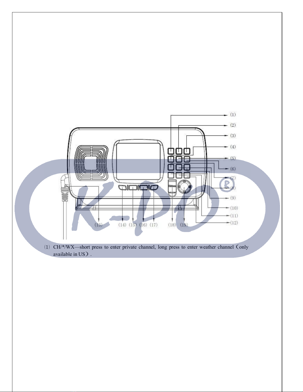
2.Front Panel/Back Panel/Wiring diagram..................................................................................3
3.LCD Display .................................................................................................................................6
4. Main Menu Operation on Screen ..............................................................................................7
DSC Menu................................................................................................................................7
MY MMSI ID setup ..........................................................................................................8
Individual Call/Position Request/Group Call/Test call ................................................9
All Ship Call...................................................................................................................11
Receive Call Log............................................................................................................12
Send Call Log ................................................................................................................13
Phone Book ....................................................................................................................14
DSC Setup......................................................................................................................14
Main Menu ............................................................................................................................15
VHF Operation..............................................................................................................16
GPS Setup ......................................................................................................................18
AIS Setup(Only HM380S).........................................................................................19
ATIS Operation .............................................................................................................20
DSC Operation ..............................................................................................................20
System Config ................................................................................................................21
Distress Menu & Send the Distress Message ......................................................................22
AIS Operation (Only HM380S)......................................................................................23
5.Key Operation ............................................................................................................................24
Power on/off & rotate to get up/down function ..................................................................24
Special Function of DISTRESS key & Real-time DSC......................................................24
VOL/AIS Control ..................................................................................................................24
TRIW/HAIL (Tri Watch/Hailer)..........................................................................................25
Squelch/MOB Key.................................................................................................................25
DW/ FOG (Dual Watch/Foghorn)........................................................................................25
MEM Key ..............................................................................................................................25
Scan Key ................................................................................................................................26
Hi/Lo.......................................................................................................................................26
Up/Down Key ........................................................................................................................26
LOC/DX.................................................................................................................................26
16/9 Key..................................................................................................................................27
Select second priority channel..............................................................................................27
CALL/MENU ........................................................................................................................27
Back Light..............................................................................................................................27
CH/*/WX ...............................................................................................................................27
6.Other Features and Solutions....................................................................................................28
Special function keys.............................................................................................................28
TX Time Out..........................................................................................................................28

The Local Time & Date on Screen: .....................................................................................28
NMEA 0183 and NMEA 2000 ..............................................................................................29
Appendix B – Channel List ..........................................................................................................30
International Marine VHF Channels & Frequencies ..................................................30
U.S. Marine VHF Channels and Frequencies ..............................................................32
Notes: ....................................................................................................................................33
Specification...........................................................................................................................38

1 .Installation
The first installation solution
1.Place and fasten the mounting bracket on the console by 4 screws;
2. Mount the base station onto the bracket;
3. Attach the supplied mounting knobs from two sides of the bracket to fix the
base station securely (as shown above).
The second installation solution:
1 Slide the fixed mount VHF through the corresponding hole on the instrument
panel or anywhere you plan to install this VHF. As the below picture shown
—
1
—

2 Use screwdriver respectively tighten the screws on either side of the small mental
bracket (as A screw of the below picture shown), make the small metal bracket fit
tightly on the aluminum chassis
3 Similarly, use screwdriver respectively tighten the screws on either side of the small
metal bracket (as B screw of the below picture shown), that will firmly against the
inside of the instrument panel.
—
2
—

HM380/HM380C/HM380S Mounting Template

2. Front Panel/Back Panel/Wiring diagram
Front Panel
⑴CH/*/WX—short press to enter private channel, long press to enter weather channel
(
only
available in US
)
.
⑵Back Light On/Off—short press to back light On/Off.
⑶Call/MENU—short press to enter “DSC Menu”, long press to enter “Main Menu”.
⑷16/9—short press to enter channel 16 or press this button to quit all other modes and back to the
priority channel quickly, long press will get second-priority channel 09 or any channel that you’ve
set as second-priority channel.
⑸LOC/DX—short press to get conversion between local and distance mode (DX allows normal
receive sensitivity; and “LOCAL” eliminates receiver noise, but degrades receiver sensitivity
meanwhile “LOCAL” icon display on LCD).
⑹HI/LO—short
p
ress to to
g
g
le between 25watt and 1 watt out
p
ut. “HI” or “LO” icon a
p
p
ears on
LCD display to indicate setting.
⑺SCAN—short
p
ress to enter all scan/all memor
y
scan, lon
g
p
ress to enter
p
riorit
y
all/memor
y
—
3
—

—
9
—
scan.
⑻MEM—short press to enter memory mode, long press to save/delete memory channel.
⑼DW/FOG—short press to enter Dual Watch Mode, long press to enter “Foghorn Menu”.
⑽SQL/MOB—short press to get SQL setting, long press to get MOB activated.
⑾TRIW/HAIL—short press to enter Tri Watch Mode, long press to enter “HAILER LISTEN
MODE” and set volume as you wish.
⑿VOL/AIS—short press to enter volume set, long press to enter AIS (Automatically
Identification System HM380S only).
⒀Handset connector.
⒁Generally it acts exit function as “Exit” icon show on screen. At initial screen, it also acts UP
key function;
⒂Soft key--short press to get channel up, long press to make channel up much faster.
⒃Soft key--short press to get channel down, long press to make channel down much faster.
⒄Generally it acts enter function as “Enter” icon show on screen. At INITIAL screen, it also acts
Down key function;
⒅DISTRESS—Pull up key cover and press to start Distress Alert Calling if you programmed
your radio with an MMSI number.
⒆Power on/off—short press to turn it on, long press to turn it off. Rotate knob to get up/down
function when radio is on.
Back Panel
Wiring diagram

—
1、HM380/HM380S/HM380C
⑴RF antenna
⑵Power +
⑶Power -
⑷Hailer
⑸external speaker jack
⑹NMEA 0183
⑺NMEA 2000(only for HM380S/HM380C)
⑻GND hole
The details please check the below table
Serial
Number
General
Description Function Description Different Color
Description
⑴
RF antenna
connector connect with antenna ﹨ ﹨
⑵red&black power Power supply Red Power+
+13.8V

—
⑶Black Power-
GND
⑷Black Phone Jack Hailer
White HAILER+
Black HAILER-
⑸Black 3.5 mm Jack External Speaker
Red AUDIO+
Black GND
⑹Mini-DIN in Black
NMEA0183
&
USB Green USBTX
Red USBRX
Green USBTX
Yellow 0183_IN-
Black 0183_OUT
+
Brown 0183_OUT
-
Orange 0183_IN+
Bare GND
⑺C connector NMEA2000
Bare Shield
Red +12V
Black GND
White CANH
Blue CANL
⑻
GND connection
hole ﹨ ﹨ ﹨
Only use the power cable with fuse supplied:

—
3.LCD Display
DSC INT
25W
P-CH 16
S
Q
L:5
VOL:3 DISTRESS
12:07:38
02 MAY 2014 Fri
CH ▲CH▼
4
.
M
a
i
n
M
enu
O
p
era
t
i
on on
S
creen
DSC Menu
Short press the CALL/MENU key will be displayed as below on LCD:
DSC Menu
Individual Call
Position Request
All Ship Call
Group Call
Test Call
Receive Call Log
Send Call Log
Phone Book
DSC Setup
My MMSI ID
EXIT ▲ ▼ ENTER
Detailed entrance for each catalogue as shown below:

—
\

MY MMSI ID setup
Firstly, long press CALL/MENU key to enter “Main Menu”.
Secondly, select “DSC Operation” to enter “MY MMSI ID”.
Then you can set up your related MMSI ID as below, generally you need to double confirm the
MMSI ID. Once confirmed, your MMSI ID will be locked by this radio.
My MMSI ID
123456789
EXIT
When input 9 digits, UP/DOWN key used for choosing the number from 1 to 9. You need to input
all numbers from the left to right one by one until all finished. Once fulfilled 9 digits, then press
“ENTER” to confirm.
—
8
—

My MMSI ID
Input MMSI
123------
EXIT ▲ ▼ ▶
My MMSI ID
123456789
EXIT
Individual Call/Position Request/Group Call/Test call
Press the “CALL/MENU” key and choose“Individual Call”, then choose “Input Address” or
“From Phonebook”.
Take individual call as example—
Firstly you selected the “Input Address”, then input 9 digits manually such as 100000000 for your
address as below:
Input Address
Input 9 digits
0-----------
EXIT ▲ ▼ ▶
Then select the t
y
p
e of individual call such as Routine
—
9
—

Individual Call
R
o
u
t
i
ne
Exit ▲▼ Enter
Next select the
p
referred channel such as 01
p
ort o
p
eration and confirm to call
Individual Call
Select Channel:
01 port ops/vts
03 unauth orized
05 port ops/vts
06 inter ship
07 commercial
08 commercial
Exit ▲▼ Enter
Individual Call
To: 100000000
Safety
Telephony by
Channel 01
Exit
C
a
l
l
Then the individual call is sent as below shown
DSC USA
LO
SQL:5 01A
PORT OPERAT/UTS
Elapsed 00
:
12
Exit
—
10
—

All Ship Call
Select the All Ship item
DSC Menu
Individual Call
Position Re
q
uest
A
l
l
S
h
i
p
C
a
l
l
Grou
p
Call
Test Call
Receive Call Lo
g
Send Call lo
g
Phone Book
DSC Setup
My MMSI ID
Exit ▲▼
E
n
t
e
r
All Shi
p
Call
S
a
fe
t
y
Ur
g
enc
y
Exit ▲▼ Enter
Safety
Select Channel:
01 port ops/vts
02 unauthorized
03 port ops/vts
04 inter ship
05 commercial
06 commercial
Exit ▲▼ Enter
—
11
—

All Ship Call
To : All Ship
Urgency
Telephony by
Channel 07
Exit Call
DSC USA
LO
SQL:5 07A
COMMER
CIAL
Elapsed 00
:
04
Exit
The All Ship Call is sent.
Receive Call
Log
When received DSC, you can check those messages from the “Distress Menu” and see the
exact message.
DSC Menu
Individual Cal
Position Request
All Ship Call
Group Call
Test Call
Receive Call Log
Send Call Log
Phone Book
DSC Setup
My MMSI ID
Exit ▲▼ Enter
—
12
—

Receive
cal
l
log
Distress
c
all
O
thers
ca
ll
Exit ▲▼ Enter
Received DSC
Distress call
Undesignated
From: 123456789
GPS POS; Unknown
88: 88 UTC
Exit Delete
Send Call Log
Press “CALL/MENU” key to choose “Send Call Log” item and see previous distress call, MOB
call and other call that you have sent.
DSC Menu
Individual Call
Position Request
All Ship Call
Group Call
Test Call
Receive Call Log
Send Call Log
Phone Book
DSC Setup
My MMSI ID
EXIT ▲ ▼ ENTER
—
13
—

Send Call Log
Distress Call
MOB Call
Others Call
EXIT ▲ ▼ ENTER
Phone Book
Press “CALL/MENU” key to choose “Phone Book” item and can check the contacted ship by
“Buddy List” and “Group List”
DSC Menu
Individual Call
Position Request
All Ship Call
Group Call
Test Call
Receive Call Log
Send Call Log
Phone Book
DSC Setup
My MMSI ID
EXIT ▲ ▼ ENTER
Phone Book
Buddy List
Group List
EXIT ▲ ▼ ENTER
DSC Setu
p
—
14
—
This manual suits for next models
2
Table of contents