K9Safety K9Caller User manual

Installation Manual
K9Caller™
Phone: 877-K9-SAFE-T
Phone: 877-597-2338
Located in Glendale, AZ
www.K9Safety.com
K9Caller™Version 1
Rev 5
Copyright K9Safety 2009

Page 2
Table of Contents
Page 1 Cover
Page 2 Table of Contents
Page 3 Getting Started
Page 4 Wire Connection Example; Connections A8-A7
Page 5 Wire Connections A6-A2
Page 6 Wire Connection A1 In Park Sense
Page 7 Wire Connections M16-M9
Page 8 Wire Connections M8-M2
Page 9 Wire Connection M1
Page 10 Wire Connections L5-L1
Page 11 Door Lock Diagrams
Page 12 Wire Connections i6-i1
Page 13 Ignition Harness Diagram
Page 14 & 15 Connections at a Glance
Page 16 Side Connectors; iData, Prog, Temp Probe, Antenna, Sensor
Page 17 Temperature Probe
Page 18 Two Way Antenna
Page 19 Program Mode, extra remote
Page 20-21 Programming Mode & Branches/Features Chart
Page 22-23 Programmable Branches/Features Explained
Page 24-25 Programmable Branches/Features Explained
Page 26-27 Optional Door Pop Hardware

Page 3
Please read this manual thoroughly.
The K9Caller is an integrated canine temperature protection system, remote controlled
alarm and keyless entry system, and remote starter in one package. The patented and patent
pending features of this unit are not available anywhere else. Please refer to the operation
manual for specific features.
Before you get started there is some information that you should be aware of to plan for a
proper installation. Most vehicle today have an anti-theft feature built into the ignition key
that provides a coded signal which must be present in conjunction with turning the key
cylinder to start the vehicle. Additionally, some vehicle are keyless and require only a
transponder fob and push button to start the vehicle. In either of these cases an addition
module is required to allow for the proper operation of the system. Some of the modules
can affect the way that an installation is planned as they require different wires and or cir-
cuits to be connected. You should always obtain a vehicle wire locator and compatibility
chart for any vehicle before the installation. You should also review the installation instruc-
tions for any additional module or accessory before you start the install. If your installation
facility does not already have access to this information you can contact our support at sup-
port@K9Safety.com and we will supply the information to you. We will need to know the
make, model and year of the vehicle with your request.
Good installations always start with planning. Knowing the features and options that the
end user is expecting will help in planning how to install and what programmable functions
need to be changed from default. For a list of options see page 19.
Also, planning where connections will be made, how wires will be routed, and where mod-
ules will be mounted helps to alleviate problems from arising during or after the installa-
tion. Make sure that connections are secure and module are properly mounted so as not to
obstruct the operation of other vehicle components. It is recommended that you contact our
support team if this is the first time that you are installing one of our systems. We can pro-
vide you with information that can reduce installation time and avoid unnecessary trouble
shooting.
Getting Started
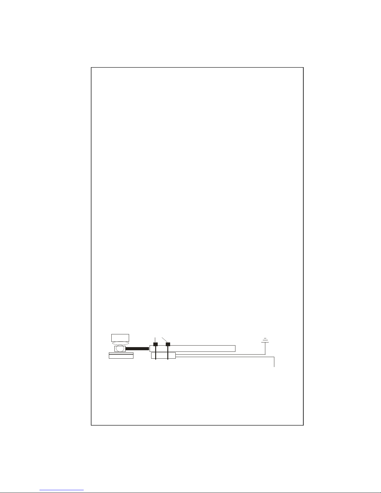
Main Control Unit, 2-Way Antenna, LCD Remote (2-Way), LCD Leather Case, AAA
Battery, 1-Way Remote with Batter, Compact Siren, Combo Status & On/Off Button, Hood
Switch, Magnetic Park Safety Contact Set, Ignition Harness, Door Lock Harness, Main
Harness, Auxiliary Harness, Temperature Probe, Starter Disable/AntiGrind Relay, Installa-
tion & Operators Instructions.
Standard Package Contents

Page 4
When connecting system wires to vehicle wires it is recommended
that you use the wire wrap technique.
Strip away 1/2”of the insulation on the vehicle wire. Evenly part
the strands of the vehicle wire. Strip away 1”of insulation at
the end of the system wire. Thread the un-insulated portion of the
system wire between the parted strand of the vehicle wire. Wrap
the threaded un-insulated system wire around the un-insulated
vehicle wire. Wrap electrical tape to cover the un-insulated system
and vehicle wire connection.
Vehicle Wire
System Wire
Find an accessible location inside the vehicle cabin to mount the MCU
keeping in mind how you will run the cables for the ignition harness and for
the programmable temperature display (CTD). Planning your installation will
ultimately save time and help to avoid service returns in the future.
A8 Orange/White, Disarmed Output (-) 500ma. This wire can be used to trigger a relay to
close when the alarm function is disarmed.
A7 White/Red, Aux 1 Output (-) 500mA. This output can be programmed to trigger when
remote button 5 is pressed followed by button 3. The output will trigger while the button is
held/ for a period of time/ or latch on/off depending on the selection made in programming
Branch 18. It can also be programmed to output when the vehicle has been started by a Hot
temperature trigger which can be useful to automatically turn on an air conditioner system or
fan(s).
Wire Connection Technique
A1-A8 Wire Connections Described

Page 5
A6 Black/Yellow, Aux 2 Output (-) 500mA. This output can be programmed to trigger when
remote button 5 is pressed followed by button 4. The output will trigger while the button is
held/ for a period of time/ or latch on/off depending on the selection made in programming
Branch 17.
A5 Blue/White, K9Funtion On/Off Status LED (-12v) Output. This wire connects to the
negative side (Gray wire) of the Status LED located in the combo LED/Pushbutton harness.
The Black wire which runs along side the Gray wire on the combo harness is the positive
wire for the LED. The positive side must be connected to a positive batter y constant source.
Note, there is a 1.5K resister inline on this wire to lower the voltage to the LED See Fig be-
low.
A4 Blue/Yellow, Glow Plug (-/+) Input. This wire connects to the wait to start indicator lamp
output on a diesel powered vehicle. This input is selectable between positive or negative sens-
ing. The factory default is set to negative. The settings are changed by changing jumper set-
tings on the board and in Program Branch 33. Note, the polarity can be changed between
negative and positive depending on the jumper setting. See Fig J1 on page 9.
A3 Blue, Trunk Trigger Input (-). This wire connects to a trunk trigger input, such as a pin
switch, to detect forced entry and trigger the alarm function.
A2 Blue/Black, K9Function On/Off & Alert Delay Input (-). This wire connects to the first
black wire of the push button switch located in the combo LED/Pushbutton harness. The
second Black wire which runs along side the first black wire on the combo harness is the
negative input wire for the switch. The negative side must be connected to a chassis ground
constant source. See Fig below
A1-A8 Wire Connections Described, Continued
Combo LED/Switch
Page 5
Battery Positive
A5 Blue/White
A2 Blue/Black
Chassis Ground

Connect this wire to a circuit that provides a negative signal when the vehicle is in park.
This can be done by connecting to a factory park safety circuit or by using the provided SFT
contact set. This wire must be connected for the system to work properly.
Under the driver's side dash, or at the steering column, find the automatic transmission shift
mechanism or strut. Find a mounting location in the park position in which the safety con-
tact and magnet can be located 1/4in apart, tip to tip. Remove the cover to expose the adhe-
sive backing on the magnet & stick in place. Use silicon or epoxy glue to form a permanent
hold and let it set until tacked. Use tie straps to attach the contact to the shift stabilizing
strut. With a multi-meter attached to the white wires of the contact, you should read a closed
circuit when the vehicle is in park. If your meter does not read a closed circuit, gradually
move the contact closer to the magnet unit you have a closed circuit. Now move the trans-
mission from the park to the reverse position, the meter should now show an open circuit. If
the circuit is still closed, gradually move the contact away from the magnet until the circuit
show open. If you have made this adjustment test again that the circuit shows closed when
in park. Once properly aligned you can permanently fix the contact in place with silicone or
epoxy glue. Connect one of the white contact wires to chassis ground.
Determine if the vehicle is factory equipped with an "in park" output. To work properly it
must supply a 12 volt negative signal with a 500mA headroom capacity. This means that in
addition to the load of the circuits it is designed to supply this signal must be capable of sup-
porting an additional 500mA. NOTE, if you are uncertain about the capacity or functionality
of a factory "in park" circuit DO NOT TIE INTO IT. On many newer vehicles the side ef-
fects will not be realized right away and can cause undesired operation. It is wiser and easier
to user the park safety contact set that is supplied in the kit then to track down problems
later!
Transmission Shift Linkage
Shifter mounting
bracket
Magnet Contact
Tie straps
White wires
To In Park Wire
Page 6
A1 Green/White, Transmission In-Park Input (-)
A1-A8 Wire Connections Described, Continued

M16 Brown/White, Horn Honk Output (-) 500mA. This wire provides a negative flashing
output to honk the vehicles horn. This output is used as an audible high temperature alert.
M15 Blue/Orange, Auto Start Activation Output (-) 500mA {Bypass Module & Ign2}. This
wire provides a negative output during the auto start and auto run of the system. It can be
connected to the activation input of a factory bypass module or used to activated addition
ignition relays.
M14 Green/White, Brake Pedal Input (+). This wire connects to the positive output side of
the brake pedal switch. The switch is typically located directly above the brake pedal and the
wire show positive when the brake pedal is pressed and goes away when the pedal is released.
M13 Black/Gray, Tachometer or Fuel Injector Input (AC 3-6v). This wire connects to the
negative (signal) side of an ignition coil or injector wire. The tach or injector wire typically
output between 3-6 volts AC. Note, the unit is shipped with Smart Start as the factory default.
Using tach sense is more reliable and is the recommended setting. For this wire to be used you
must change Branch 30 to option 2 and program the tach signal within Branch 31 option 1.
M12 Red, +12 Battery Positive Input (+). Connect this wire to a constant 12V battery positive
source capable of 15Amps.
M11 Black, Chassis Ground Input (-). Connect this wire to a good chassis ground. A factory
chassis ground lug is preferred.
M10 Pink, Factory Alarm Disarm/Ignition Output (-) 500mA. This wire can be used to dis-
arm a factory alarm system to allow remote start operation or to energize an additional relay
to supply an ignition output. See Branch 16 for programming.
M9 White, Parking Light Output (+/-) selectable. Connect this wire to the vehicle parking
light controller or wire. This output is selectable between positive or negative sensing. The
factory default is set to positive. Note, the polarity can be changed between negative and posi-
tive depending on the jumper setting. See Fig J1 on page 9.
M1-M16 Wire Connections Described
Page 7

M1-M16 Wire Connections Described, Continued
M8 White/Black, Hood Trigger Input (-) {shutdown}. Connect this wire to either a factory
hood pin switch that provides a negative signal when the hood is open or to the provided
hood switch. This connection is vital to prevent the system from auto starting the vehicle
while the is being serviced. Failure to properly connect this wire can result in an acci-
dental start and possibly injury. A magnetic contact or mercury switch can also be used.
M7 Black/White, Hot Temperature Alert Output (-) 500mA. This wire provides a steady
negative output while the temperature is at or above the alert threshold and the alert condi-
tion is triggered. It can be used to activate and optional window drop module, trigger an
optional SMS messenger or to energize a relay that can operates additional fans.
M6 Brown, Siren Output (+) 3A. Connect this wire to the positive side (red wire) of the
siren. It supplies a positive output when the alarm function is triggered and when the alarm
function is armed or disarmed if selected. See Branch 21 and remote operation.
M5 Violet, Door Trigger Input (+). Connect this wire to a factory door pin switch or dome
light trigger that shows positive when the doors are open and no positive when the doors are
closed. Traditionally a Ford type door trigger.
M4 Green, Door Trigger Input (-). Connect this wire to a factory door pin switch or dome
light trigger that shows negative when the doors are open and no negative when the doors are
closed. Traditionally a GM type door trigger.
M3 White/Violet, Window Up Output (-) 500mA. This wire will supply a 60 second nega-
tive output upon deactivation of a high temperature alert or a momentary negative output
upon deactivation of an auto start/run cycle. This wire can be used to trigger a window roll
up module.
M2 Orange, Alarm Armed Output (-) 500mA. This wire supplies a negative output while
the alarm system is armed. It is used to trigger the included starter disable/starter anti-grind
relay. This relay will disable the vehicle from being started when the security alarm is active
and will also prevent the starter from grinding if the vehicle is “auto-started”and the user
turns the ignition key to the start position.
Page 8

M1 Gray, Door Pop Trunk Pop (+/-) 7A Selectable. This wire provides a selectable positive/
negative 7Amp relay output that can be programmed for either door pop output or trunk pop
output. When selected as a door pop, this wire will send the selected output only when the
vehicle is in park and the K9 system is activated when triggered by the appropriate remote
signal button 3 or by an external trigger (See Branch 12). Connect this wire to the green pop
solenoid wire to pull the solenoid and ground the blue or to the blue wire to push and ground
the green. When selected as a trunk pop, this wire will send the selected output only when
triggered by the appropriate remote signal button 3. See program Branch 10 and Note, the
polarity can be changed between negative and positive depending on the jumper setting. See
Fig J1 below. Also, if both door pop and trunk pop are desired then use either aux1 or aux2
for trunk pop.
Please see pages 22-23 of this manual for instruction on installing the optional door pop hard-
ware.
M1-M16 Wire Connections Described, Continued
Page 9
Fig J1 : Jumper Selections On Board

Page 10
The system is equipped with built in door lock relays that enable you to connect to a wide
variety of factory and aftermarket power door lock systems. On many new vehicles the
power lock system can be controlled by connecting to the vehicle data bus through a 3rd
party data module. Ask for a vehicle specific wire locator for more details.
L5 Green, Door Lock Output (Relay N.O.). This is the lock output wire which is connected
to the vehicle wire that causes the vehicle door locks to lock. There are several different
types of door lock systems available on automobiles today. Review the type specified for
the current vehicle and connect accordingly.
L4 White, Door Lock Normally Closed (Relay N.C.). This wire is used when connecting to
L3 Blue, Unlock Output (Relay N.O.). This is the unlock output wire which is connected to
the vehicle wire that causes the vehicle door locks to unlock. There are several different
types of door lock systems available on automobiles today. Review the type specified for
the current vehicle and connect accordingly.
L2 Brown, Unlock Normally Closed (Relay N.C).
L1 Violet, Common Lock & Unlock. This signal is the common input to the Green and
Blue wires. If this is connected to +12V then a positive output will be sent to the Green and
Blue wires. If this is connected to chassis ground then a negative output will be sent to the
Green and Blue wires.
L1-L5 Door Lock Relays

Door Lock Connector
LU
Door Lock
Buttons
Door Lock Solenoid
Green
White
Blue
Brown
Violet Ground
Battery Pos
or Ground
X
X
No Connection
No Connection
Lock
Unlock
Door Lock Connector
L U
Door Lock
Buttons
Door Lock Solenoid
Green
White
Blue
Brown
Violet
Battery Pos
X
X
N
o
t
e
:
A
l
i
g
h
t
t
e
s
t
e
r
c
o
n
n
e
c
t
e
d
t
o ground
will light when you lock & unlock.
Wires are in drivers kick panel
Negative or Positive system with factory relays.
L1-L5 Door Lock Relays, Continued
Positive reverse polarity door lock system.
Page 11

Page 12
i6 Violet, Starter Output. This wire provides a positive output to crank the engine and start
the vehicle when auto start is initiated.
i5 Yellow, Ignition 1 Output. This wire provides a positive output to energize the vehicle’s
primary ignition circuit during the duration of auto start and auto run. It also acts as a sen-
sor to determine when the ignition key is on.
i4 Orange, Accessory Output. This wire provides a positive output to energize a vehicle’s
accessory circuit after the vehicle has auto started and during the duration of auto start and
auto run.
i3 Brown, Accessory 2 Output. This wire provides a positive output to energize a vehicle’s
accessory circuit after the vehicle has auto started and during the duration of auto start and
auto run.
i2 Red, Battery Input 1. This is a main battery input for auto start and run functions. This
wire can be connected at the vehicle ignition switch wire harness.
i1 Red, Battery Input 2. This is a main battery input for auto start and run functions. This
wire can be connected at the vehicle ignition switch wire harness.
i1-i5 Ignition Harness Connections

i1-i5 Ignition Harness Connections, Continued
Page 13
NormClosed
Common
NormOpen
Red
Red
Brown
Orange
Yellow
Violet
NegCoil
PosCoil
PosCoil
NegCoil
PinM15
Blue/Orange
PinM2
Orange
Common
X
Cut
Bottom Main
Connector
2nd Ignition
Relay
Starter Disable
Anti Grind Relay
Ignition
Connector
Top Main
Connector
Ignition
Key Switch
Ignition 2
Starter
Ignition 1
Accessory 1
Accessory 2
Battery Constant
Battery Constant

Page 14

A8 Orange/White
A7 White/Red
A6 Black/Yellow
A5 Blue/White
A4 Blue/Yellow
A3 Blue
A2 Blue/Black
A1 Green/White
M16 Brown/White
M15 Blue/Orange
M14 Green/White
M13 Black/Gray
M12 Red
M11 Black
M10 Pink
M9 White
M8 White/Black
M7 Black/White
M6 Brown
M5 Violet
M4 Green
M3 White/Violet
M2 Orange
M1 Gray
L5 Green
L4 White
L3 Blue
L2 Brown
L1 Violet
i6 Violet
i5 Yellow
i4 Orange
i3 Brown
i2 Red
i1 Red
Disarmed Output (-) 500ma
Aux 1 Output (-) 500mA
Aux 2 Output (-) 500mA
K9Funtion On/Off Status LED (-) Output
Glow Plug (wait to start) (+/-)
Trunk Trigger Input (-)
K9Function On/Off & Alert Delay Input (-)
Transmission In-Park Input (-)
Horn Honk Output (-) 500mA
Auto Start Output (-) 500mA {Bypass & Ign2 }
Brake Pedal Input (+)
Tachometer or Fuel Injector Input (AC 3-6v)
+12 Battery Positive Input (+)
Chassis Ground Input (-)
Factory Alarm Disarm/Ignition Output (-) 500mA
Parking Light Output (+/-) selectable
Hood Trigger Input (-) {shutdown}
Hot Temperature Alert Output (-) 500mA
Siren Output (+) 3A
Door Trigger Input (+)
Door Trigger Input (-)
Window Up/Factory Alarm Arm Output (-) 500mA
Alarm Armed Output & Anti-grind(-) 500mA
Door Pop Trunk Pop (+/-) 7A Selectable
Door Lock Output (Relay N.O.)
Door Lock Normally Closed (Relay N.C.)
Unlock Output (Relay N.O.)
Unlock Normally Closed (Relay N.C)
Common Lock & Unlock
Starter Output
Ignition 1 Output
Accessory Output
Accessory 2 Output
Battery Input 1
Battery Input 2
Page 15

Side Harness Connections
Side
Harness
Connections
S4 White, K9System On Trigger/Warn Away. This wire can be configured to either auto-
matically turn on the K9 system whenever a ground signal is applied or to trigger the alarm
sensor warn away signal when the alarm system is armed. See program branch 6.
S3 Black, Ground Out.
S2 Blue, External Pop Receiver (Pro)/Impact Sensor trigger. This wire can be configured to
either trigger the door pop function when a ground signal is applied and the K9 system is
activated or to trigger the alarm impact signal when the alarm system is armed. See program
branch 12.
S1 Red, Battery Positive Out.
Sensor Connections
Page 16

Mounting the Temperature Probe
Temperature Probe Connector
Take care not to locate the remote temperature probe in front of a vent or in direct sunlight as
this will cause the system to have an inaccurate temperature reading. Also, if hanging the
probe from the roof, make sure there is a least 4 inches of wire hanging as close proximity to
the roof will cause the temperature probe to sense a higher temperature level .
The probe comes prewired with 8 feet of cable. This cable can be lengthened up to 30 ft with-
out adversely affecting performance.
Page 17

Page 18
Plastic
Window Post
Cover
Vehicle
Head-Liner
Window
Antenna
Placement
Find a location near the rear view mirror to mount the 2-Way antenna. Clean the surface of
the inside of the window where mounting is to be done. Remove the adhesive film cover
from the pager antenna and stick on to the window. The wire can be tucked under the
vehicle head-liner and run behind the plastic window post cover.
Mounting the 2-Way window Antenna

Programming LCD 2-Way and Standard 1-Way Transmitters
When adding a 2-way LCD transmitter to the system ( maximum of two LCD Transmit-
ters total) Any previously stored transmitter will be erased if it is not programmed within
the following sequence.
1. Turn the ignition key On, Off, On, Off, On, Off, and back On. (Key On 4 times)
wait for the siren*/horn to chirp/honk 4 times (approx 3-5 seconds later )
2. Press and hold the antenna button for 5 seconds .
· The siren*/horn will chirp/honk 4 times.
· The LED will illuminate.
3. Press and release Button 1 on the first transmitter, then on the second transmitter.
· The siren*/horn will chirp/honk once for every transmitter learned.
4. Turn off the ignition key.
5. The siren*/horn will chirp/honk 3 times to indicate the system has exited programming
mode.
When adding a 1-way transmitter (maximum of four) Any previously stored transmitter
will be erased if it is not programmed within the following sequence.
1. Turn the ignition key On, Off, On, Off, and back On. (Key On 3 times)
wait for the siren*/horn to chirp/honk 3 times (approx 3-5 seconds later )
2. Press and hold the antenna button for 5 seconds .
· The siren*/horn will chirp/honk 3 times.
· The LED will illuminate.
3. Press and release Button 1 on the first transmitter, then on the second transmitter.
· The siren*/horn will chirp/honk once for every transmitter learned.
4. Turn off the ignition key.
5. The siren*/horn will chirp/honk 3 times to indicate the system has exited programming
mode.
Page 19

Page 20
Changing Programmable Features
This system is compatible with both the LCD 2-way transmitter or the standard 1-way
transmitter, all system programming can be performed using either one.
To enter System Programming:
1. Turn on ignition.
2. Within 5 seconds, press the valet switch 5 times.
· The siren*/horn will provide three chirps/honks, indicating that you have entered Pro-
gramming.
3. Press the valet switch the number times equal to the System Parameter you want to
change.
· The siren*/horn will chirp/honk each time the valet switch is pressed.
4. Within 5 seconds, press the transmitter button corresponding to the desired operating
mode for
that System Parameter.
· The siren*/horn will chirp/honk to indicate the setting.
1 chirp/honk = Button 1
2 chirps/honks = Button 2
3 chirps/honks = Button 3
4 chirps/honks = Button 4
5. When you are finished, turn off the ignition to save the changes.
Some of the features should only be changed by a qualified technician.
These features are denoted with Tech.
Other feature can be changed by the user and they are denoted with User.
Default Reset
Following this procedure will set all System Programming Parameters to factory default
settings.
1. Turn on ignition.
2. Within 5 seconds, press the valet switch 5 times.
· The siren*/horn will provide three chirps/honks, indicating that you have entered Pro-
gramming.
3. Press Transmitter Button 3.
· The siren*/horn will chirp/honk 6 times indicating that the reset signal was received.
· All System Programming parameters are now set to factory default settings.
· The Valet Mode is off.
4. Turn off ignition.
Other manuals for K9Caller
2
Other K9Safety Remote Starter manuals