Kahlenberg KB-30 User manual

Kahlenberg Instruction Sheet KB-30 Horn System Rev. 10/03/2011, Page 1 of 8
KB-30 Electronic Horn System
INSTALLATION, OPERATION, AND MAINTENANCE INSTRUCTIONS
1) GENERAL - The Kahlenberg KB-30 is an Electronic Horn/Hailing system for marine
use that produces in excess of 130 dB (1/3 Octave Band) @ 1 Meter, as required by IMO
Regulations for vessels up to 75 meters in length. The KB-30 also serves as a voice
amplification unit. The KB-30 System consists of two major components being the KB-30
Horn/Driver Unit, and the M-511D control/microphone unit. The function of the KB-30 Horn is
that of a high powered speaker. The function of the M-511D Whistle Control is to provide
convenient operation of a sound signaling device from a single control panel for At-Will,
Restricted Visibility, and Maneuvering signaling as required. The M-511D also generates the
SOLAS General Alarm Signal, or may be integrated with another alarm system on board which
generates this signal. The M-511D is to be used with the KB-30 Electronic Horn Assembly,
and can also be used with an additional secondary signaling device such as a Kahlenberg
Air Horn. A horn selector switch is included on the M-511D to select between the KB-30 and
secondary horn.
2.) Contents of the KB-30 Horn System Include:
(1) KB-30 Horn Assembly, including mounting bracket and cable per Drg. 3-6445
(1) M-511D Control Unit, including console mount unit per Drg. 3-6435, microphone
connection cable, microphone, and microphone mounting bracket per Drg. 3-6436
(1) Spare Fuse, 5 x 20mm 3 Amp Fast Burn
(1) Spare Fuse, 5 x 20mm 8 Amp Fast Burn
2) OPERATION -
D.C. VOLTAGE REQUIREMENT:_______24 VOLTS D.C.
CURRENT REQUIREMENT OF M-511D: __.25 Amps
SWITCHING CAPACITY OF M-511D:_____1.75 Amps Maximum (“Horn 1)
_____8 Amps Maximum (KB-30 Horn/Hailer)
CAUTION: THE M-511D IS FUSE PROTECTED, HOWEVER, BE CERTAIN NOT
TO EXCEED THE 1.75 AMP MAXIMUM SWITCHING CAPACITY. THIS CAN
OCCUR IF MULTIPLE DEVICES ARE CONNECTED TO THE HORN 1 CIRCUIT
SUCH AS ADDITIONAL LIGHTS OR SOUND PRODUCING DEVICES. A
SUITABLE RELAY MUST BE INSTALLED FOR CONTROLLING THESE
DEVICES.

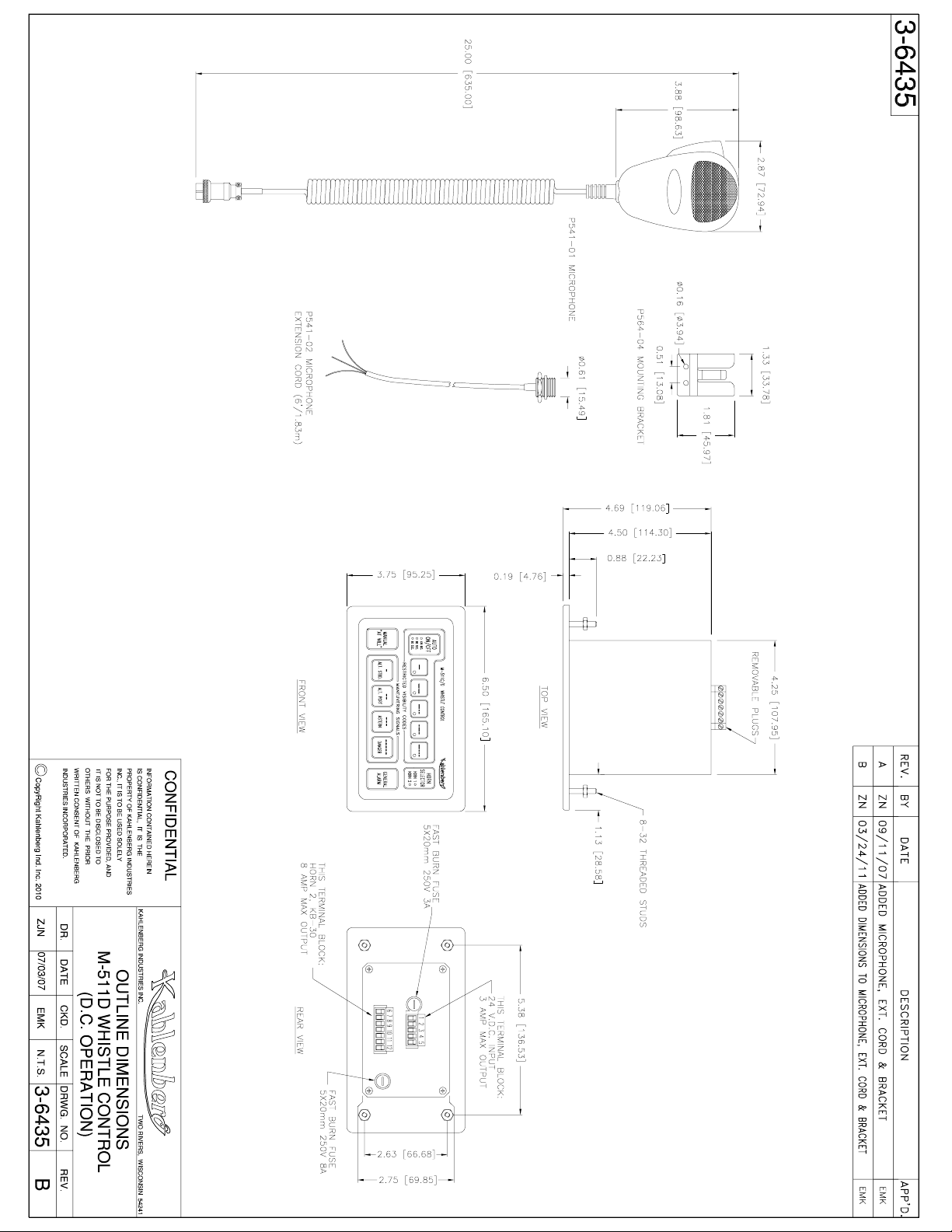
Kahlenberg Instruction Sheet KB-30 Horn System Rev. 10/03/2011, Page 2 of 8
The M-511D is designed to activate the KB-30 Electronic Horn, and/or an additional solenoid
valve or similar horn-activating device operating on 24 Volts D.C.. The “HORN SELECTOR”
switch is used to select which horn will be activated by the M-511D. “Horn 1” setting (the
default setting on power up) will send signals to the solenoid valve (if installed) for an air horn.
“Horn 2” setting will send signals to the KB-30 Electronic Horn. If only using the KB-30
Electronic Horn with the M-511D, “Horn 2” must be selected. Once “Horn 2” is selected,
the control will save this setting when it is turned off. Note that in the case of a dual horn
installation, remote at-will push buttons if installed will activate both horns simultaneously when
the HORN SELECTOR switch is set on “Horn 2”. When “Horn 1” is selected, only the air horn
(if installed) will be activated by remote push buttons.
The Activation of the signal sent to the horns can be accomplished several ways depending upon
the type of signal desired. For “At-Will” operations use the “Manual/At-Will” button, this
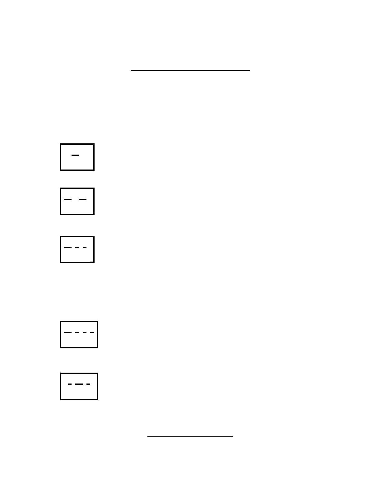
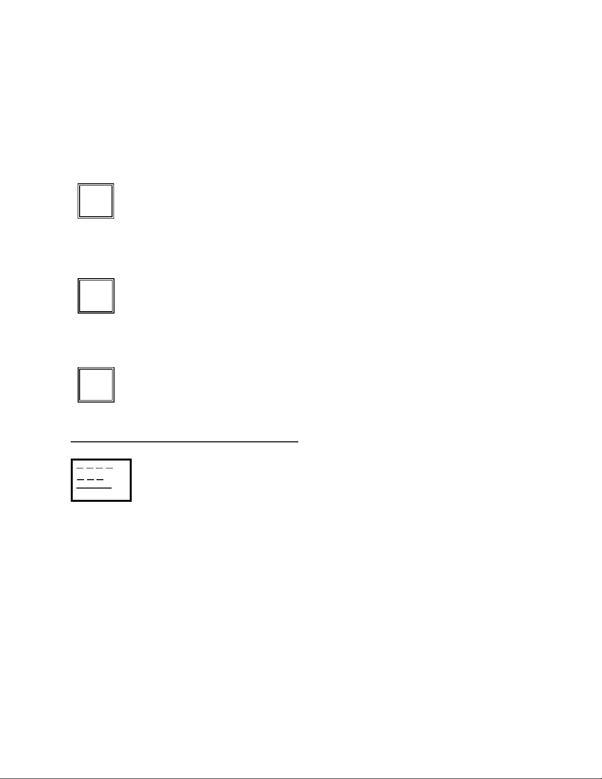
button will signal the device instantly at all times regardless of the mode of operation. There are
five (5) predetermined Restricted Visibility codes within the M-511D and they are indicated on
the associated button of the keypad. For a definition of these codes and their uses, refer to the
reference sheet included with these instructions. Pressing the “Auto On/Off” button activates the
five code buttons. Upon activation of the Automatic mode, the red LED light of the activated
code will light and signaling of the device for that code will commence after a 10 second delay.
This designed delay is to prevent commencement of the activated code prior to selection of a
new code or proper preparation at listening posts. A new code can be selected at any time during
automatic operation and will commence after the 10 second delay. Termination of the Automatic
Mode can be accomplished by either depressing the “Auto On/Off” button, activating any of the
Maneuvering Signal codes, activating the “At-Will” button (the latter two will also cause
instantaneous signaling of the device), or activating the “General Alarm” button.
The M-511D has the ability to change the cycle times between restricted visibility signaling. The
default setting is 120 seconds between blasts, which is also regulation. When initially powered
up the 120 second LED on the “Auto On/Off” will be lit, signifying the 2-minute interval. The
other two intervals are 90 seconds, and 60 seconds. To change the signaling interval depress and
hold the “Auto On/Off” button for 5 seconds then release and the next LED will be lit, continue
this procedure until the desired interval is attained.
For quick easy signaling of required maneuvering codes the M-511D includes four (4) preset
codes with a descriptive reference included on the keypad. For a complete explanation of these
codes please refer to the attached reference sheet. When a maneuvering code button is pressed,
the horn will instantaneously signal the code and terminate the Auto mode (if on).
IMPORTANT NOTE:
The KB-30 Horn is an intermittent duty unit designed for normal “at-will” and automatic
signaling requirements. The demand placed on the horn driver is great when in horn
signaling modes. To protect the unit, a thermal disconnect switch in the horn driver will

Kahlenberg Instruction Sheet KB-30 Horn System Rev. 10/03/2011, Page 3 of 8
shut off the unit for several seconds if the horn is used excessively over a short period of
time. The M-511D Control also includes software which will reduce the volume at the horn
if the horn button is depressed for more than 10 seconds continuously. These features are
by design to protect the horn driver from overcurrent situations that might cause damage
to the unit.
The M-511D is designed to be used as a single unit or in conjunction with other M-511C units,
and with multiple remote “At-Will” buttons, such as the Kahlenberg M-131A, M-126, or any
customer supplied two contact button. Refer to the wiring diagram included with these
instruction sheets for your particular application.
General Alarm Code: The M-511D is also equipped with a General Alarm code which is
activated by depressing and holding the “General Alarm” button for 3 seconds. This function
will stop all other functions on the M-511D and can only be stopped by depressing the “Auto
On/Off” button. When the General Alarm is activated all three LED’s on the “Auto On/Off”
button will be illuminated at the same time.
Microphone: The M-511D also includes a remote microphone connection with female console
mount jack, microphone and microphone mounting bracket for hailing purposes. When the
microphone is activated, the voice signal overrides all other functions of the M-511D Controller.
Auxiliary Input: The M-511D allows for an input signal from a mono output jack from a radio,
CD Player or similar device. This signal will be broadcast over the KB-30 Horn Speaker, but
will be overridden by the horn signal or voice commands from the microphone.
4) INSTALLATION -
WARNING: BE SURE TO SHUT OFF POWER, TAG OUT, AND VERIFY NO
VOLTAGE IS PRESENT BEFORE INSTALLING OR ATTEMPTING TO SERVICE
THIS UNIT. FAILURE TO FOLLOW THIS WARNING COULD RESULT IN SERIOUS
INJURY OR DEATH.
The M-511D mounts easily into a console and is secured by fastening the bezel to the console
with four (4) #8 x 1-1/4" self-clinching studs already attached. An opening of 4-3/8" wide by 2-
7/8" high should be made in the console where the unit is to be placed. The M-511D is shipped
with 1 loose gasket for installations exposed to the elements. The gasket has a removable
adhesive backing and is used to provide a seal between the Bezel and Console. Simply remove
the adhesive backing and secure in place. An additional bead of RTV silicone sealant may be
applied around the perimeter of the Bezel for additional weather protection.

Kahlenberg Instruction Sheet KB-30 Horn System Rev. 10/03/2011, Page 4 of 8
ELECTRICAL CONNECTION DETAILS: IMPORTANT!!!
THE ENTIRE 50 FT (15 METERS) OF SUPPLIED 16AWG (2 x 1.3mm) MARINE
CABLE MUST BE INSTALLED BETWEEN THE KB-30 HORN AND M-511D
CONTROL.
USE OF WIRE LARGER IN DIAMETER OR SHORTER IN LENGTH CAN CAUSE
PERMANENT DAMAGE TO THE HORN. USE OF WIRE SMALLER IN DIAMETER
OR LONGER IN LENGTH WILL RESULT IN LOSS OF HORN OUTPUT.
FOR INSTALLATIONS WHERE MORE THAN 15 METERS OF CABLE ARE
NEEDED, CONSULT THE FACTORY FOR SPECIFIC WIRE DIAMETER REQUIRED.
It is suggested that the wiring to the male terminal plugs be completed prior to securing the bezel
(Refer to the attached wiring diagram).
Connect the terminal plug to the timer. It is recommended that the perimeter of the terminal
block be sealed with a RTV silicone sealant.
**NOTE: Once power is connected to the KB-30, a low level white noise will be produced
by the horn speaker. This is normal and is the sound of low level current at the horn used
to heat the driver and prevent condensation.
5) CARE AND MAINTENANCE - The M-511D Whistle Control is designed to provide
many years of maintenance free operation. However, included with the M-511D are replacement
fuses for each of the circuit boards as referenced on the attached parts list. There are no
additional spare parts we suggest you keep on hand. However if any parts listed on the attached
Parts List drawings are required for any reason, please refer to the associated part number when
ordering. If the M-511D should fail to operate properly please contact Kahlenberg Brothers
Company for recommended action or return to Kahlenberg for prompt analysis and repair.
When cleaning the membrane switch panel, we recommend the use of Windex (or equivalent) or
a mild soap/water solution applied with a soft cotton cloth.
6) DRAWING REFERENCES
Outline Dimensions: #3-6435
Parts List: #3-6436
Wiring Diagram: #3-6443
**For custom installations other than those shown in the above wiring diagrams see
custom wiring diagrams provided by Kahlenberg or contact Kahlenberg Industries
with specific requirements.

Kahlenberg Instruction Sheet KB-30 Horn System Rev. 10/03/2011, Page 5 of 8
RESTRICTED VISIBILITY CODES
RULE 35
INTERNATIONAL & INLAND
IN OR NEAR AN AREA OF RESTRICTED VISIBILITY, WHETHER BY DAY OR NIGHT,
THE SIGNALS PRESCRIBED IN THIS RULE ARE AS FOLLOWS:
One Prolonged Blast (Every 2 minutes)
Making Way through the water
Two Prolonged Blasts (Every 2 minutes)
Underway but stopped and making no way through the water
One Prolonged Blast and Two Short Blasts (Every 2 minutes)
Vessel not under command
Vessel restricted in her ability to manuever
Vessel constrained by her draft
Sailing Vessel
Vessel engaged in fishing
Vessel engaged in towing or pushing another vessel
One Prolonged Blast and Three Short Blasts (Every 2 minutes)
A Vessel towed or if more than one Vessel is towed the last Vessel
of the tow, if manned. When practicable, this signal shall be
made immediately after the signal made by the towing Vessel.
One Short Blast, One Prolonged Blast, One Short Blast (Every
Minute) Vessel at Anchor
*Note: The above is intended as a quick reference guide only and in no way is intended to
be a replacement for the complete Rule 35 as included in the 72' COLREGS
MANEUVERING CODES

Kahlenberg Instruction Sheet KB-30 Horn System Rev. 10/03/2011, Page 6 of 8
RULE 34
INTERNATIONAL - RULE (A)
WHEN VESSELS ARE IN SIGHT OF ONE ANOTHER, A POWER-DRIVEN VESSEL
UNDERWAY, WHEN MANEUVERING AS AUTHORIZED OR REQUIRED BY THESE
RULES, SHALL INDICATE THAT MANEUVER BY THE FOLLOWING SIGNALS ON
HER WHISTLE:
One Short Blast
“I am altering my course to Starboard”
Two Short Blasts
“I am altering my course to Port”
Three Short Blasts
“I am operating Astern Propulsion”
Five Short Blasts
“Danger”
Failure to understand intentions or actions, or in doubt
*Note: The above is intended as a quick reference guide only and in no way is intended to
be a replacement for the complete Rule 34 as included in the 72' COLREGS
ALT STBD
ALT PORT
ASTERN
DANGER

Kahlenberg Instruction Sheet KB-30 Horn System Rev. 10/03/2011, Page 7 of 8
INLAND - RULE (A)
WHEN POWER-DRIVEN VESSELS ARE IN SIGHT OF ONE ANOTHER AND MEETING
OR CROSSING AT A DISTANCE WITHIN HALF A MILE OF EACH OTHER, EACH
VESSEL UNDERWAY, WHEN MANEUVERING AS AUTHORIZED OR REQUIRED BY
THESE RULES:
One Short Blast
“I intend to leave you on my Port side”
In Agreement
Two Short Blasts
“I intend to leave you on my Starboard side”
In Agreement
Three Short Blasts
“I am operating Astern Propulsion”
In Agreement
Five Short Blasts
“Danger”
Doubt Safety of Proposed Maneuver
*Note: The above is intended as a quick reference guide only and in no way is intended to
be a replacement for the complete Rule 34 as included in the 72' COLREGS
ALT STBD
ALT PORT
ASTERN
DANGER

Kahlenberg Instruction Sheet KB-30 Horn System Rev. 10/03/2011, Page 8 of 8
INLAND - RULE (C)
WHEN IN SIGHT OF ONE ANOTHER (I) A POWER DRIVEN VESSEL INTENDING TO
OVERTAKE ANOTHER POWER DRIVEN VESSEL SHALL INDICATE HER INTENTION
BY THE FOLLOWING SIGNALS ON HER WHISTLE:
One Short Blast
“I intend to overtake you on your Starboard side”
In Agreement
Two Short Blasts
“I intend to overtake you on your Port side”
In Agreement
Five Short Blasts
“Danger”
Failure to understand intentions or actions, or in doubt
GENERAL EMERGENCY ALARM CODE:
Seven Short Blasts followed by 1 long blast (repeats every 10 seconds)
IMO SOLAS GENERAL EMERGENCY ALARM SIGNAL
*Note: The above is intended as a quick reference guide only and in no way is intended to
be a replacement for the complete Rule 34 as included in the 72' COLREGS
ALT STBD
ALT PORT
DANGER


Table of contents