Kaipule IX30-Z-Wave User manual

IX30 - Z-Wave PIR Detector User Guide
Ⅰ. Introduction
IX30-Z-Wave is a digital micro-control intrusion detector adopting Energy Accumulation Logical Processing & Random
Dynamic Time Segmentation Technology. With precise columnar Fresnel lens, IX30-Z-Wave can increase its energy receiving
efficiency and sensitivity without false alarm. In conjunction with advanced software technology, it will make an accurate
judgment between real intruder & interference factors that may cause false alarm. Superior ability to detect & prevent false
positives.
The pulse number is optional, suitable for kinds of residential constructions, preventing false positive & false negative that other
ordinary indoor detectors cannot do. Its performance is far beyond other ordinary PIR alarms. Besides, we use large capacity
built-in battery & special power saving solution, battery working life is up to 2 years.
Ⅱ.Specification
Model No.: IX30-Z-Wave
Detection Distance: 10m @ 25℃
RF Range: indoor linear distance <=30m
Input Voltage:3VDC(2PCS LR 6 1.5V alkaline battery)
Current:16μA(standby)/35mA (alarm)
Detection Range: as the diagrams

Optical Lens Data
Infrared Area:11+8+6+5(typical)
Max. Detection Square:10m*10m/90°
RF Frequency: 908.4MHZ
Alarm Indicator: LED indicator on <= 1s
Mount Bracket: 1 PCS (default)
Mounting Height: 2.2~2.7m (87~106 inch)
Operating Temperature: -20℃~50℃
Storage Temperature: -20℃~60℃
Anti White Light (Indoor): >6500LUX
Dimension: 110*62*47mm (L*W*H)
Ⅲ.Installation
3.1 Installation Guide
Do not face heat / cold sources Avoid direct sunshine Away from high-voltage line
Do not install on the unstable place Do not face to the metal wall
3.2 Dial Switch Description
IX30 can be set 3 types of operation modes as below:
Test Mode: Alarm will only betriggered again with above 5s interval from its first alarm. After triggered, it will
send alarm elimination signal to the relevant device in at least 30s.
Power-save Mode: Alarm will only be triggered again with above 3min interval from its first alarm. After
triggered, it will send alarm elimination signal to the relevant device in at least 3 minutes.
Code Mode: without any function
Jumper Setting
IX 30 has the following 3 types of pulse options:

One pulse: The detector alarms when it detects one pulse.
Two pulses: The detector alarms when it detects two pulses.
Three pulses: The detector alarms when it detects three pulses.
The higher the pulse count is, the lower the sensitivity will be, but high pulse count can reduce false alarm.
3.3. Battery Replacement:
When in low voltage status, detector will send signal to the alarm control, then the user should replace the battery in time.
Remove the bottom cover, and put the new battery in right polarity. (As the picture)
Ⅳ.Walking Test in Detection Area
1. Set the detector to test mode to perform walking test. Pulse count can be set by PULSE 1, 2, 3.
2. Walk breadthwise from any direction at the remote detection coverage at the speed of
0.75m/s, then the LED indicator blinks for 1 second and alarm triggered. (As the right picture)
3. Test in different direction to confirm the two boundaries of detection. Ensure the detector
rightly points to the central detection zone.
4. The center of detection zone should not uphill inclined. In order to obtain a good detection
range, please adjust the vertical detection range, to ensure the detector is in right position.
5. Perform the walk test again as above when you have adjusted the detection range.
6. When the detector passed the walking test, please adjust the test mode to normal mode
Please don’t invert the detector while installing. Here advice user to have a walk test every week.
V. IX30-Z-Wave Operation
1. Add & Remove
Add : enter the Inclusion Mode of gateway, and press the tamper switch 3 times within 1.5s, then the door sensor
will stay in enrollment state until successfully enrolled into network or enrollment time out after 30s.
Remove: enter the Exclusion Mode of gateway, and press the tamper switch 3 times within 1.5s, then the door
sensor will be removed after a period of time.
2. Association Groups Description
The sensor has 2 associations Inclusion Mode in groups, Lifeline group can support 1 device only, Group 2 can

support 2 devices.
It will send “NOTIFICATION_REPORT”to the device in Lifeline group when the door sensor is opened / closed,
tamper switch is triggered / recovered.
When in low battery status, door sensor will send “BATTERY_REPORT” to Lifeline group device periodically.
The door sensor will send “DEVICE_RESET_LOCALLY_NOTIFICATION” to Lifeline group device when the
device recovers to factory settings.
When the door sensor is opened, it will send “BASIC SET” command to control these devices in Group2.
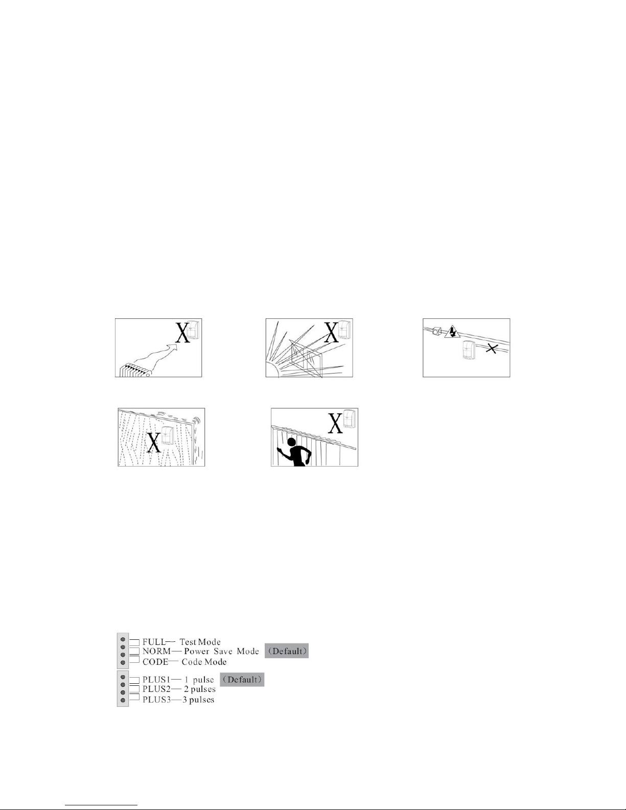
3. Restore Factory Settings
Press the anti-tamper switch for 6 times within 2.5 seconds to restore factory settings.
4.Wake-up
a) Manual Wake-up
Quickly press tamper switch once, the door sensor will automatically send wake-up information, and there will be
10s after wake-up to receive gateway setting information.
b) Automatic Wake-up
Default time of automatic wake-up is 24 hours, and there will be 10s after wake-up to receive gateway setting
information, the max automatic report time = 24 hours, minimum=30min
5. Lifeline Group
a)When the door sensor is opened or recovered, it will send “Binary Sensor Report” and “Notification Report”
commands to the device under Lifeline group.
When door sensor is opened:
Sensor Binary Report, Value = 0xFF, Type = 0x0C
Notification Report, Notification Type = 0x07, Event = 0x08
When door sensor is recovered:
Sensor Binary Report, Value = 0x00,Type = 0x0C
Notification Report, Notification Type = 0x07, Event = 0x00
b)When tamper switch is triggered or recovered, the door sensor will send “Sensor Binary Report” and
“Notification Report” command to the device under Lifeline group.
Tamper Triggered:
Sensor Binary Report, Value = 0xFF,Type = 0x08
Notification Report, Notification Type = 0x07, Event = 0x00
Tamper recover (press tamper switch for 0.5s):
Sensor Binary Report, Value = 0x00, Type = 0x08
Notification Report, Notification Type = 0x07, Event = 0x00
c) Low Battery Report: Battery Report
When the door sensor is wake-up from sleep mode, it will check its battery status; once low battery, it will send
Battery Report command to the device under Lifeline group every hour;
Battery Report, Battery Level = 0xFF
6. Association Group2

If there is any device under Association Group2, the door sensor will send “BASIC SET” command to control
those devices when the door sensor is triggered. For example: when the door sensor is triggered, it sends adjustable
parameter “BASIC SET” command to a lamp under Group2, you can adjust the lamp’s luminance through the
parameters of this command; if the set light-up time out (see the Configuration Description), the sensor will send
“BASIC SET”command to turn-off the lamp.
When sensor is triggered:
[Command Class Basic,Basic Set,Value = 0xFF(default 0xFF, configurable, see the Configuration Description)]
When light-up time out:
[Command Class Basic,Basic Set,Value = 0x00]
7. Configuration Description
a) “Basic Set” configuration
If there is any device under Association Group2, the PIR sensor will send “Basic Set = value” command to control
that device when the door sensor is opened. “Value” configuration rule is as below:
Function Parameter Byte Range Default
Basic Set Level 1 1 1-100 or 0xFF 0xFF
b) Turn Off Light Time Configuration
If there is any device under Association Group2, the PIR sensor will send “Basic Set = value” command to Group2,
and send “Basic Set = 0x00” command to turn-off light after “5 x t” seconds,
Set value = “t”, means to send Basic Set command after “t” seconds.
Function Parameter Byte Range Default
Turn Off Light Time 2 1 1-24 4
c) PIR Sensor Alarm Elimination Time Configuration
Min set time is 5s. If the configuration is 1, that means it will eliminate alarm after 1*5s (5 seconds), if t, will
eliminate alarm after t*10s.
Function Parameter Byte Range Default
Alarm Elimination Time 3 1 1-24 4
Z-Wave Supportive Commands
Generic Deice Type =
GENERIC_TYPE_SENSOR_BINARY
Specific Device Type =
SPECIFIC_TYPE_ROUTING_SENSOR_BINARY
Support Command Class =
COMMAND_CLASS_ZWAVEPLUS_INFO_V2
COMMAND_CLASS_ASSOCIATION_V2
COMMAND_CLASS_WAKE_UP_V2

COMMAND_CLASS_BATTERY
COMMAND_CLASS_ZWAVEPLUS_INFO_V2
COMMAND_CLASS_ASSOCIATION_GRP_INFO
COMMAND_CLASS_NOTIFICATION_V4
COMMAND_CLASS_SENSOR_BINARY_V2
COMMAND_CLASS_MANUFACTURER_SPECIFIC_V2
COMMAND_CLASS_VERSION_V2
COMMAND_CLASS_POWERLEVEL
COMMAND_CLASS_DEVICE_RESET_LOCALLY
Commands to Control Other Devices:
COMMAND_CLASS_BASIC
8. Cautions
Our products have been quite stable in performance, but as the product itself low point
transmission capacity and conditional application, it still has limits in usage. Following are the
situations that may occur:
a) Indoor environmental restrictions, such as co-frequency interference, complicated
geographical environment of communication etc
b) Detectors low voltage
c) Not standard Z-Wave Gateway
Warning: If the problems caused by user’s incorrect operation, our company will not be
responsible for it!
This product can be included and operated in any Z-Wave network with other Z-Wave certifid
devices from other manufacturers and/or other applications. All non-battery operated nodes
within the network will act as repeaters regardless of vendor to increase reliability of the network
FCC STATEMENT :
This device complies with Part 15 of the FCC Rules. Operation is subject to the following
two conditions:
(1) This device may not cause harmful interference, and (2) This device must accept any
interference received, including interference that may cause undesired operation.
Warning: Changes or modifications not expressly approved by the party responsible for
compliance could void the user's authority to operate the equipment.
NOTE: This equipment has been tested and found to comply with the limits for a Class B
digital device, pursuant to Part 15 of the FCC Rules. These limits are designed to provide
reasonable protection against harmful interference in a residential installation. This
equipment generates uses and can radiate radio frequency energy and, if not installed
and used in accordance with the instructions, may cause harmful interference to radio
communications. However, there is no guarantee that interference will not occur in a
particular installation. If this equipment does cause harmful interference to radio or
television reception, which can be determined by turning the equipment off and on, the
user is encouraged to try to correct the interference by one or more of the following
measures:
Reorient or relocate the receiving antenna.
Increase the separation between the equipment and receiver.
Connect the equipment into an outlet on a circuit different from that to which the
receiver is connected.
Consult the dealer or an experienced radio/TV technician for help.
Table of contents
Popular Accessories manuals by other brands

Omron
Omron ZFX-SC50S instruction sheet

Pure Essential Oil Works
Pure Essential Oil Works 308575 Important instructions

adapx
adapx Capturx user guide

ORION TELESCOPES & BINOCULARS
ORION TELESCOPES & BINOCULARS 9969 instruction manual

VOLTCRAFT
VOLTCRAFT PB-17C operating instructions

Osprey
Osprey ARIEL 65 owner's manual