Installation Instructions
5 | P a g e v1.1 ( 0 8 / 2 0 1 9 )
TRIMLESS INSTALLATION
SKU# 177092 - Trimless Frame Kit is required for installation, this is sold separately and contains Parts C & D.
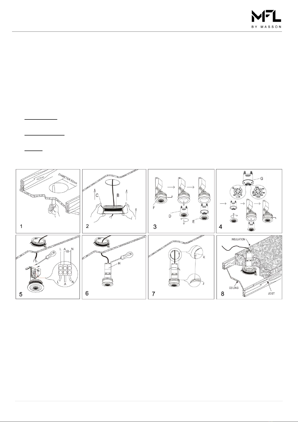
1. Remove the trim (B) from the frame body (A). Install the trimless frame (D - not included, sold separately) and the ring
(C - not included, sold separately) onto the frame body (A). Fig.1
2. Cut an installation hole of Ø 92mm into the ceiling. Fig.2
3. Insert the trimless frame assembly (A, C, D) into the ceiling and align with the installation hole. Fig.3
4. Secure the trimless frame (A,C ,D) by installing two screws through the ceiling and allow the head to countersink into
the plasterboard. Fig. 4 The screw heads should be countersunk into the plasterboard by 1-2mm. Fig. 5
5. Adjust the ring (C) so it is 1-2mm above the plaster board level.
6. Plaster the ceiling to cover the screw heads and the ring (C). Wait for it to dry Fig. 6 Sand back the plaster until the
surface is smooth Fig. 7 Repaint the ceiling Fig. 8
7. Remove the PIR sensor (F) from the inner frame (E) by loosening the grub screws with an allen key. Fig.9
8. Remove the lens (G) from the sensor (F) by rotating it anti-clockwise. Fig.9 & 10
SENSOR SETTINGS:
DURATION TIME: Adjust the duration time by turning the “TIME” knob, the length of time the switch will remain on
after activation can be adjusted from 10secs ±5 to 15mins ±2. The duration time is pre-set to 3 minutes;
NOTE: Once the sensor has been triggered by the PIR sensor, any subsequent detection will start the timed period
again from the beginning, the sensor will remain on until there is no movement detected.
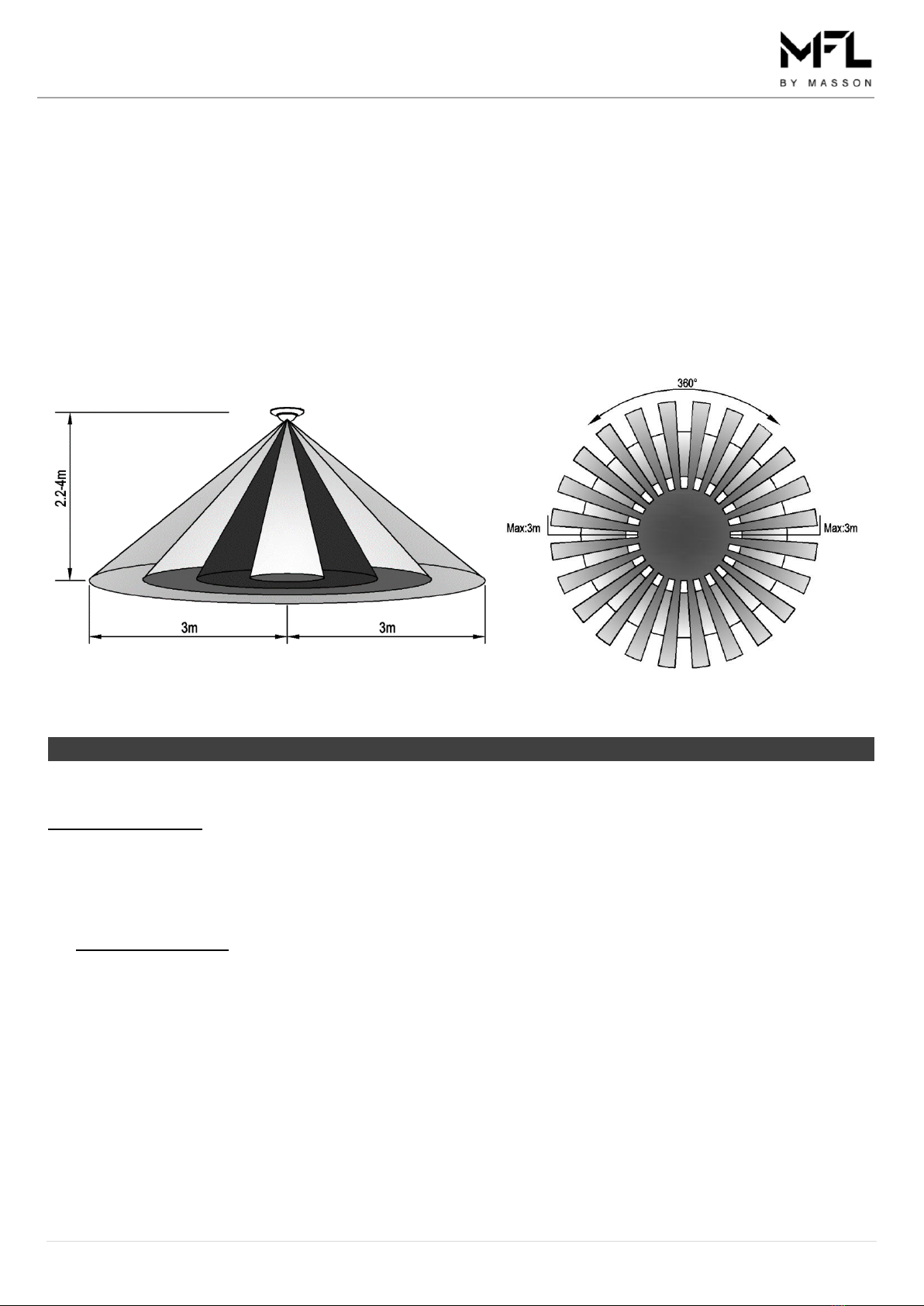
LUX LEVEL: Adjust the LUX level by turning the “LUX” knob to change the LUX level from 3 lux to 2000 lux. The
sensor will switch on when the ambient light is lower than the setting LUX level. The LUX lever pre-set to 30 lux.
9. Reinstall the lens on to the sensor and the sensor back in to inner frame.
10. Remove the terminal block cover by loosening the screw. Connect the mains supply wire to the terminal block. Fig.11
Mains Supply Wire Terminal Block Label
Neutral – Blue N (Neutral)
Live – Brown L (Live)
Connect the luminaire wires to the terminal block.
Luminaire Wire Terminal Block Label
Neutral – Blue N (Neutral)
Live – Brown A (Live)
11. Ensure that the wires are secure and no bare wires are exposed. Secure the mains supply wire and luminaire wires
with the cord anchorage by tightening the screws. Fig. 12
12. Install the cover back onto the terminal block and secure with the screw. Fig. 12
13. Insert the sensor assembly (I) into the frame (A) and secure it by rotating the tabs (J) into the grooves (K) until it locks
into position. Fig.13
14. Sensor function:
AUTO MODE: Switch on the wall switch to the sensor, the light connected to the sensor will be ON-OFF-ON, after 12
seconds the sensor will be in the auto mode. The sensor will switch the lights on and off automatically.
MANUAL MODE: While in auto mode, switch the wall switch OFF-ON-OFF-ON within 3 seconds, the sensor will be
continuously on for 8 hours (manual mode). After 8 hours, the sensor will return back to the auto mode.
RESET: To return the sensor to auto mode during manual mode, turn the switch OFF for at least 20 seconds and ON
again. The sensor will now be in auto mode.