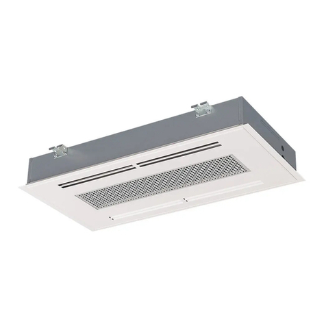
Kampmann KaCool D AF User manual

Ceiling cassette
KaCool D AF
Installation and operating instructions
Keep these instructions in a safe place for future use!
I 543/12/18 EN | SAP-Nr. 1291188

2
.
3.25
KaCool D AF –
Comfortable feeling of well-being, thanks to AtmosFeel
Chilled water air conditioning system
Installation and operating instructions
1 General ............................................................................... 5
1.1 About these instructions ...................................... 5
1.2 Explanation of symbols ........................................ 5
1.3 Copyright protection............................................ 6
1.4 Customer service................................................... 6
2 Safety ............................................................................... 7
2.1 Intended use ......................................................... 7
2.2 Limits of operation and use ................................. 7
2.3 Fundamental dangers........................................... 8
2.3.1 Danger from electrical energy............................. 9
2.4 Responsibility of the operator ............................. 9
2.5 Instruction ............................................................. 10
2.6 Personnel requirements ....................................... 10
2.6.1 Qualications........................................................ 10
3 Technical data ..................................................................... 11
3.1 Main dimensions................................................... 11
3.2 Connection values................................................. 13
3.3 Operating data ..................................................... 13
4 Construction and function................................................. 14
4.1 Overview ............................................................... 14
4.2 Brief description.................................................... 16
4.3 Accessories............................................................. 17
5 Transport, packaging and storage .................................... 22
5.1 Safety information for transport......................... 22
5.2 Transport inspection ............................................. 23
5.3 Packaging.............................................................. 24
5.4 Storage .................................................................. 24
6 Installation and connection............................................... 25
6.1 Requirements governing the installation site..... 25
6.2 Service openings with sealed ceilings.................. 25
6.3 Electrical wiring .................................................... 32
6.4 Overview of controls ............................................ 34
6.5 Electromechanical model with AC fan ................ 35
6.6 Electromechanical model with EC fan................. 40
6.7 Model with infra-red remote control.................. 44
Contents

3
KaCool D AF –
Comfortable feeling of well-being, thanks to AtmosFeel
3.25
Chilled water air conditioning system
Installation and operating instructions
6.8 KaControl model................................................... 50
6.8.1 Operation of the KaController ............................ 51
6.8.1.1 Function keys, display elements........................... 52
6.8.1.2 Operation.............................................................. 53
6.9 Alarm messages .................................................... 64
6.10 KaController installation...................................... 65
6.10.1 Troubleshooting A11 – A17.................................. 66
6.11 Cabling .................................................................. 68
6.11.1 General information............................................. 68
6.11.2 KaController.......................................................... 68
6.11.3 External room temperature sensor...................... 69
6.11.4 Inputs for processing external contacts
(e.g. on-site BMS etc.)........................................... 69
6.11.5 Internal temperature sensor / air intake sensor.. 69
6.12 Addressing – Single-circuit controls..................... 70
6.13 Settingtheunitcongurationbymeansof
DIP switches........................................................... 71
6.14 Parameter settings................................................ 74
6.15 Parameter settings................................................ 75
6.15.1 Setting absolute setpoint temperature or ± 3K.. 75
6.15.2 ON/OFF, Eco/Day function .................................... 76
6.15.3 Heating/cooling changeover via clip-on sensor
in 2-pipe systems................................................... 77
6.15.3.1 Setting DIP switch no. 3, DIP switch no. 4 ........... 77
6.15.3.2 Automatic heating/cooling changeover mode
setting.................................................................... 78
6.15.3.3 Heating mode limit values ................................... 78
6.15.3.4 Cooling mode limit values.................................... 79
6.15.3.5 Cyclic opening and closing of the straight
valve or 3-way valve ............................................. 79
6.15.4 Function of digital inputs DI1 and DI2 ................ 80
6.15.4.1 Function of DI1 ..................................................... 80
6.15.4.2 Function of DI2 ..................................................... 81
6.15.5 Function of digital outputs V1 and V2 ................ 82
6.15.5.1 Digital output V1.................................................. 82
6.15.5.2 Digital output V2.................................................. 82
6.15.6 External control via 0..10 Volts ............................ 83
Contents
4
.
3.25
KaCool D AF –
Comfortable feeling of well-being, thanks to AtmosFeel
Chilled water air conditioning system
Installation and operating instructions
6.16 Functional testing of connected assemblies ....... 84
6.17 Parameter list for control PCB.............................. 85
6.18 KaController parameters...................................... 88
7 Operation and commissioning .......................................... 92
7.1 Pre-commissioning checks.................................... 92
7.2 Venting the heat exchanger ................................ 93
7.3 Switching on ......................................................... 93
8 Maintenance....................................................................... 94
8.1 Securing against reconnection............................. 94
8.2 Maintenance ......................................................... 95
8.2.1 Filter cleaning ....................................................... 95
9 Faults ............................................................................... 96
9.1 Fault display .......................................................... 96
9.2 Fault table ............................................................. 97
10 Declaration of Conformity................................................. 98
Contents

5
KaCool D AF –
Comfortable feeling of well-being, thanks to AtmosFeel
3.25
Chilled water air conditioning system
Installation and operating instructions
1 General
1.1 About these instructions
Theseinstructionsensurethesafeandefcienthandlingofthis
equipment. These instructions form an integral part of the unit
and must be kept in the direct vicinity of the unit and available
to personnel at all times.
All personnel must have carefully read through these
instructions prior to commencing all work on the equipment.
A fundamental prerequisite for safe working is compliance
with all the stated safety instructions and other instructions
contained in this manual.
In addition all local occupational health and safety at work
regulations apply, as do general safety provisions governing the
use of the equipment.
Illustrations in this guide are intended to provide a basic
understanding and may differ from the actual model.
1.2 Explanation of symbols
Important notes
DANGER!
This combination of symbol and signal word
indicates an immediately dangerous situation,
which will cause death or injuries if not avoided.
This symbol highlights useful hints,
recommendations and information for efcient and
trouble-free operation.
IMPORTANT NOTE!
This combination of symbol and signal word
indicates a possible dangerous situation, which can
cause material and environmental damage if not
avoided.

6
.
3.25
KaCool D AF –
Comfortable feeling of well-being, thanks to AtmosFeel
Chilled water air conditioning system
Installation and operating instructions
Other labels The following labels are used in this manual to highlight
instructions, results, listings, references and other elements:
1.3 Copyright protection
The contents of this manual are protected by copyright. Their
use is permitted when using the product. Any further use is not
permitted without written permission from the manufacturer.
1.4 Customer service
Our Customer Service team is available is available for technical
information:
We are always interested in receiving information and
experiences relating to the use of our products which could be
of value for improving our products.
Label Explanation
Step-by-step instructions
Results of actions
Reference to sections of the manual and
other applicable documents
Listswithoutspeciedsequence
[Button] Operating elements (e.g. buttons, switches)
Display elements (e.g. indicator lights)
“Display” Display elements (e.g. buttons, assignment
of function keys)
Address
Kampmann GmbH
Friedrich-Ebert-Str. 128–130
49811 Lingen (Ems) Germany
Phone +49 591 7108 670
Fax +49 591 7108 360
E-mail [email protected]
Website www.kampmann.de

7
KaCool D AF –
Comfortable feeling of well-being, thanks to AtmosFeel
3.25
Chilled water air conditioning system
Installation and operating instructions
2 Safety
This section provides an overview of all important safety
aspects to ensure optimum protection of personnel as well
as safe and trouble-free operation. Additional order-related
safety information is contained in the sections covering the
individual phases of the product's life.
2.1 Intended use
Correct and proper use is also deemed to include compliance
with all the instructions in this manual.
Any use beyond or other than the stated intended use is
considered as misuse.
The units are only intended to be used for heating and
cooling air in frost-free and dry rooms. Within the room, the
unit needs to be connected to the building's heating/cooling/
ventilation system and to the building's waste water and
power network.
2.2 Limits of operation and use
Limits of operation
Min./max. water temperature °C 5-75
Min./max. air intake temperature °C 15-35
Min./max. air humidity % 15-75
Max. operating pressure bar 8
Min./max. glycol percentage % 25-50
Water quality
pH 8-9
Conductivity µS/cm < 700
Oxygen content (O2) mg/l < 0.1
Hardness °dH 4-8.5
Sulphur ions (S) not measurable
Sodium ions (Na+) mg/l < 100
Iron ions (Fe2+,Fe3+) mg/l < 0.1
We would refer to VDI-2035 Sheets 1 & 2, DIN EN 14336 and DIN EN 14868 with regard to the
properties of the medium used to protect the equipment. The following values provide further
guidance.
The water used should be free of contamination, such as suspended substances and reactive
substances.
Manganese ions (Mn2+) mg/l <0.05
Ammonia ions (NH4+) mg/l < 0.1
Chlorine ions (CI) mg/l < 100
CO2ppm < 50
Sulphate ions (SO42-) mg/l < 50
Nitrite ions (NO2-) mg/l < 50
Nitrate ions (NO3-) mg/l < 50

8
.
3.25
KaCool D AF –
Comfortable feeling of well-being, thanks to AtmosFeel
Chilled water air conditioning system
Installation and operating instructions
2.3. Fundamental dangers
The following section lists residual risks that can be generated
by the unit even when operated as intended.
Observe the following safety instructions and the safety
information in the other sections of this manual to reduce the
risk of injury and damage to property and avoid dangerous
situations.
WARNING!
Warning of misuse!
Never operate the unit in humid areas, such as
swimming pools, wet areas etc.
Never operate the unit in rooms with an
explosive atmosphere.
Never operate the unit in rooms with a high dust
content.
Never operate the unit in rooms that contain
high-temperature gases.
Never operate the unit in aggressive or corrosive
atmospheres (e.g. sea air).
Never operate the unit above electrical
equipment, such as switch cabinets, computers
or other electrical units, or contacts that are not
drip-proof.
Never operate the unit outdoors.
Keep windows closed during operation.
Only operate the unit fully assembled and
connected to the relevant supply networks
(waste water, heating/cooling, electricity).
Never operate the unit beyond its technical
specication( Chapter 3 “Technical data” on
page 12).
Install the unit away from heaters or other
heating equipment.
Ensurethattheairowcancirculatefreely.
Never place any objects on the unit.
Never cover the unit.
Always note the requirements for the
installation site ( Chapter 6.1 “Requirements
governing the installation site” on page 27).

9
KaCool D AF –
Comfortable feeling of well-being, thanks to AtmosFeel
3.25
Chilled water air conditioning system
Installation and operating instructions
2.3.1 Danger from electrical energy
Electric current
2.4 Responsibility of the operator
Duties of the operator The unit is operated in the commercial sector. The operator of
the unit is therefore subject to the legal obligations concerning
occupational health and safety.
In addition to the safety instructions in these operating
instructions, the valid safety, accident prevention and
environmental protection regulations must be observed for the
area of use of the unit.
The following applies in particular:
The operator must be aware of the applicable health and
safety regulations and determine in a risk assessment other
hazards that may arise from the special working conditions
at the site of operation. He then has to implement this in
the form of operating instructions for the operation of the
unit.
The operator must regulate and specify the responsibilities
for installation, operation, troubleshooting, maintenance
and cleaning.
The operator must ensure that all staff who work on
the unit have read and understood these instructions. In
addition, he must also train personnel and inform them of
the possible dangers at regular intervals.
It is the responsibility of the operator to provide
maintenance and repair personnel with the necessary
personal protective equipment and advise them of the
necessity to wear it.
DANGER!
Risk of fatal injury from electrocution!
Contact with live parts will lead to fatal injury
from electrocution. Damage to the insulation or
individual components can lead to a fatal injury.
Onlypermitqualiedelectricianstoworkonthe
electrics.
Immediately disconnect the system and repair it
in the event of damage to the insulation.
Keep live parts away from moisture. This can
cause a short circuit.
Properly earth the unit.

10
.
3.25
KaCool D AF –
Comfortable feeling of well-being, thanks to AtmosFeel
Chilled water air conditioning system
Installation and operating instructions
Furthermore, the operator is responsible for ensuring that the
equipment is always in perfect condition.
The following therefore applies:
The operator must ensure that the maintenance intervals
described in this manual are adhered to.
Hygiene requirements Theoperatormustcomplywiththespecicationsinline
with the pertinent legal standards and guidelines relating
to hygiene applicable at the installation site. This includes
ensuring that
fresh and waste water are hygienically separated,
the pertinent maintenance and test intervals are complied
with,
the requirements for air ducts and diffusers are complied
with,
thepredenedltergradesarecompliedwith.
2.5 Instruction
The manufacturer offers training for users. For contact details
please refer to Chapter 1.4 “Customer service” on page 6.
2.6 Personnel requirements
2.6.1 Qualications
Only permit personnel to carry out work if they can be
expected to carry out this work reliably. People with impaired
reactions, possibly due to drugs, alcohol or medication, are not
permitted to carry out work.
Qualiedelectrician
Qualiedelectricianshavebeentrainedforthespecic
environment in which they work and understand the pertinent
standards and regulations.
Installation personnel
This training provides installation personnel with the technical
knowledge and experience, as well as knowledge of the
pertinent regulations, needed to carry out the assigned tasks
and independently recognise possible dangers. Installation
personnel have all the necessary equipment and tools.
Caretakers/users
Caretakers/users have been instructed by the manufacturer in
the tasks assigned to them and possible dangers of improper
conduct. Caretakers/users are only permitted to carry out tasks
thatgobeyondnormaloperationifthisisspeciedinthis
manual.

11
KaCool D AF –
Comfortable feeling of well-being, thanks to AtmosFeel
3.25
Chilled water air conditioning system
Installation and operating instructions
3 Technical data
3.1 Main dimensions
Models 1–4, with plastic design panel (dimensions in mm)
Water connections
Weights
Model 2-pipe 4-pipe
11/ 2“ 1/ 2“
2 - 4 3/ 4“ 1/ 2“
Model
Basic unit
Design panel
Total
2-pipe 4-pipe 2-pipe 4-pipe
[kg] [kg] [kg] [kg] [kg]
121 24 324 27
223 24 326 27
323 24 326 27
424 24 327 27
2-pipe:
3Water inlet
4Water outlet
5Condensation drain
4-pipe:
1Hot water inlet
2Hot water outlet
3Cold water inlet
4Condensation outlet
5Condensation drain
3
5
5
5
31
4
425
Front view
Top view
Water connection side 4-pipe
Water connection side 2-pipe

12
.
3.25
KaCool D AF –
Comfortable feeling of well-being, thanks to AtmosFeel
Chilled water air conditioning system
Installation and operating instructions
Models 5-7, with plastic design panel (dimensions in mm)
Water connections
Weights
Model 2-pipe 4-pipe
5 - 7 3/ 4“ 3/ 4“
Model
Basic unit
Design panel
Total
2-pipe 4-pipe 2-pipe 4-pipe
[kg] [kg] [kg] [kg] [kg]
540 43 545 48
645 48 550 53
745 48 550 53
2-pipe:
3Water inlet
4Water outlet
5Condensation drain
4-pipe:
1Hot water inlet
2Hot water outlet
3Cold water inlet
4Condensation outlet
5Condensation drain
5
5
Front view
Top view
Water connection side 2-pipe
Water connection side 4-pipe
3
4
5
3
2
4
1
5

13
KaCool D AF –
Comfortable feeling of well-being, thanks to AtmosFeel
3.25
Chilled water air conditioning system
Installation and operating instructions
3.2 Connection values
Unit size Model 1 Model 2 Model 3 Model 4 Model 5 Model 6 Model 7
Mains voltage 230 V / 50 Hz
Enclosure type IP 21
Protection class I / Protective conductor connection
AC fan model
Max. power consumption W 43 63 75 89 102 108 156
Max. power consumption A 0.19 0.28 0.33 0.39 0.52 0.6 0.75
EC fan model
Max. power consumption W 11 26 45 65 81 89 155
Max. power consumption A 0.11 0.22 0.33 0.47 0.52 0.55 0.72
1) at CHW 7 / 12, tL1 = 27 °C
2) at LPHW 70/60, tL1 = 20 °C
3.3 Operating data
Valve
conguration
2-pipe system 4-pipe system
Model
Dimensions
(L x W)Cooling outputs1) Heat outputs2) Cooling outputs1) Heat outputs2)
[kW] [kW] [kW] [kW] [mm]
AC, 230 V
1.97 – 2.71 3.85 – 5.27 1.89 – 2.75 2.45 – 3.50 1
680 x 680
2.17 – 4.31 4.19 – 8.19 1.91 – 3.40 2.45 – 4.45 2
2.73 – 5.05 5.17 – 9.86 2.00 – 3.89 1.91 – 3.30 3
4.03 – 5.47 8.21 – 10.88 2.66 – 4.47 2.39 – 3.70 4
4.19 – 6.22 8.46 – 12.85 4.50 – 6.20 5.80 – 9.00 5
930 x 9305.38 – 9.56 9.22 – 17.30 4.30 – 7.20 6.30 – 10.50 6
5.38 – 11.00 10.09 – 22.66 4.50 – 8.80 6.80 – 12.50 7
EC, 230 V
1.97 – 2.71 3.85 – 5.27 1.89 – 2.75 2.45 – 3.50 1
680 x 680
2.17 – 4.31 4.19 – 8.19 1.91 – 3.40 2.45 – 4.45 2
2.73 – 5.05 5.17 – 9.86 2.00 – 3.89 1.91 – 3.30 3
4.03 – 5.47 8.21 – 10.88 2.66 – 4.47 2.39 – 3.70 4
4.19 – 6.22 8.46 – 12.85 4.50 – 6.20 5.80 – 9.00 5
930 x 9305.38 – 9.56 9.22 – 17.30 4.30 – 7.20 6.30 – 10.50 6
5.38 – 11.00 10.09 – 22.66 4.50 – 8.80 6.80 – 12.50 7

14
.
3.25
KaCool D AF –
Comfortable feeling of well-being, thanks to AtmosFeel
Chilled water air conditioning system
Installation and operating instructions
4 Construction and function
4.1 Overview
Features
3 5 6
11 1410
3
2
1
4
6
5
Punched opening for
optional fresh air
connection
Punched opening for
external air outlet
Compact basic housing
AtmosFeel air outlet
Design panel
Electrical control box

15
KaCool D AF –
Comfortable feeling of well-being, thanks to AtmosFeel
3.25
Chilled water air conditioning system
Installation and operating instructions
1Compact basic housing:
galvanised steel
theoutsidehasaeececoating
for improved insulation from the
environment
the inside has high-grade
10 mm vapour diffusion-tight
polyethylene foam matting
2Punched holes for external air
outlet:
connection option for on-site air
outlets
3Punched hole for optional fresh
air connection:
model 1-4, per spigot (max. 2)
80 m³/h
model 5 - 7, (max. 1) 120 m³/h
4AtmosFeel air outlet:
four manually adjustable outlet
air slats (model 1 - 4)
smooth plastic
easy to clean
5Electrical junction box for
control PCBs:
KaControl
infra-red electronic receiver
terminals only, for on-site control
6Design panel, similar to RAL
9010 (pure white)
outlet optimised for maximum
comfort through side air outlets
and utilisation of the Coanda
effect
IR receiver concealed within the
design panel (models 1 – 4)
7Condensation connection:
outside diameter 13.5 mm
8AirlterG1:
simple to remove
easy to clean
9Air intake grille
large free cross-section to
minimise pressure losses
10 Hydraulic connections:
for CHW, LPHW and
condensation drain
valve drip tray drains any
condensation produced into the
condensation tray
drip tray is supplied with the unit
optionally available with built-
in valves with corresponding
quantities
11 Condensationpumpandoat
switch:
easily accessible by removal of
the polystyrene condensation
tray
integrated condensation pump
drains the condensation up to a
max. head of 480 mm
pump activation by a two-stage
oatswitch
the pump is switched on when
therststageisreached,and
the second stage activates an
evaluable alarm contact
12 Fans
3-stage AC fans
continuously variable EC fans
efcientandlow-noise
protection class IP 44, insulation
class B
integrated thermal contacts
to prevent the motor from
overheating
13 Heat exchanger
copperpipewithaluminiumns
2-/ 4-pipe version
vent and drain valves on the
outside of the unit
14 Valves (optional):
optionally factory-integrated
7Condensation connection
9Intake air grille
8AirlterG1
Example; Models 1 – 4

16
.
3.25
KaCool D AF –
Comfortable feeling of well-being, thanks to AtmosFeel
Chilled water air conditioning system
Installation and operating instructions
4.2 Brief description
The KaCool D AF is a decentralised unit for heating, cooling
andlteringair,includinginhotels,ofcesandbusiness
premises.Thankstotheefcient,extremelyquietfan,the
individual comfort temperature is quickly reached.
Operating mode Secondary air is drawn into the central part of the cover panel.
Theairisroutedrstthroughtheairintakegrilletothelter.
This cleans the secondary air of dust and thus protects the
downstream components from dirt and impurities.
The air is drawn in by the fan, located directly downstream
ofthelterandpressedthroughthecopper-aluminiumheat
exchanger. Depending on the temperature at which the
mediumowsthroughtheheatexchanger,theairiseither
cooled or heated in the exchanger.
The air then passes through the outlet air slats into the room.
The outlet air slats can be manually adjusted to the required
direction.
Condensation can be produced at the heat exchanger when
cooling with low water temperatures. This drips onto the
heat exchanger and falls into the condensation tray below.
The condensation collects in a corner here. The condensation
levelismonitoredbyaoatswitch.Thecondensationpump
is activated when a certain level is exceeded. A condensation
warning is emitted if a higher level is exceeded.
The valve kits available in the accessories can be connected
to the side of the unit. The units include condensation trays,
which can be installed under the valve kits.
The condensation is guided and drained through the prepared
opening into the condensation tray of the unit.

17
KaCool D AF –
Comfortable feeling of well-being, thanks to AtmosFeel
3.25
Chilled water air conditioning system
Installation and operating instructions
4.3 Accessories
Figure Article Properties Suitable for Art. no.
Valves
2-way valve kit
Open / Close 2-pipe 230 V drive
KaCool D AF without KaControl,
model0−1 325009012110
KaCool D AF without KaControl,
model2−4 325009022110
KaCool D AF without KaControl,
model 5 325009032110
KaCool D AF without KaControl,
model6−7 325009042110
Open / Close 2-pipe 24 V drive
KaCool D AF with KaControl,
model0−1 325009012112
KaCool D AF with KaControl,
model2−4 325009022112
KaCool D AF with KaControl,
model 5 325009032112
KaCool D AF with KaControl,
model6−7 325009042112
Open / Close 4-pipe with 230 V drive
KaCool D AF without KaControl,
model0−4 325009014110
KaCool D AF without KaControl,
model5−7 325009024110
Open / Close 4-pipe 24 V drive
KaCool D AF with KaControl,
model0−4 325009014112
KaCool D AF with KaControl,
model5−7 325009024112
3-way valve kit
Open / Close 2-pipe with 230 V drive
KaCool D AF without KaControl,
model0−1 325009012120
KaCool D AF without KaControl,
model2−4 325009022120
KaCool D AF without KaControl,
model 5 325009032120
KaCool D AF without KaControl,
model6−7 325009042120
Open / Close 2-pipe 24 V drive
KaCool D AF with KaControl,
model0−1 325009012122
KaCool D AF with KaControl,
model2−4 325009022122
KaCool D AF with KaControl,
model 5 325009032122
KaCool D AF with KaControl,
model6−7 325009042122
Open / Close 4-pipe with 230 V drive
KaCool D AF without KaControl,
model0−4 325009014120
KaCool D AF without KaControl,
model5−7 325009024120
Open / Close 4-pipe 24 V drive
KaCool D AF with KaControl,
model0−4 325009014122
KaCool D AF with KaControl,
model5−7 325009024122
more »

18
.
3.25
KaCool D AF –
Comfortable feeling of well-being, thanks to AtmosFeel
Chilled water air conditioning system
Installation and operating instructions
Figure Article Properties Suitable for Art. no.
Connections
Primary air connection
spigot For the connection of external primary air
KaCool D AF model 0 - 4 325009010300
KaCool D AF model 5 - 8 325009020300
ABS design panel
RAL 9010
Included with units with article number
325008XXX001XX.
KaCool D AF model 0 - 4,
without IR remote control
Included as
standard
KaCool D AF model 0 - 4,
with IR remote control
KaCool D AF model 5 - 8,
without IR remote control
KaCool D AF model 5 - 8,
with IR remote control
RAL 9010 metal panel
The ABS design panel is included with
ceiling cassettes with article number
325008XXX001XX. To order these units
without design panel, replace the 1in the
article number by a 0and order the metal
panel separately.
KaCool D AF model 0 - 4,
without IR remote control 325009010020
KaCool D AF model 0 - 4,
with IR remote control 325009010021
KaCool D AF model 5 - 8,
without IR remote control 325009020020
KaCool D AF model 5 - 8,
with IR remote control 325009020020
Control accessories, electro-mechanical
Electromechanical
room thermostat
Only suitable for cooling with 3-stage fan
speed switch
Colour: white
Voltage: 230V, 50 Hz, max. 3 A
W x H x D: 170 x 70 x 44 mm
All models, 2-pipe
ACvalveconguration 196000148918
Electromechanical room thermostat with
manual cooling/heating switch, with
3-stage fan speed switch
Colour: white
Voltage: 230V, 50 Hz, max. 3 A
W x H x D: 170 x 70 x 44 mm
All models, 2-pipe
ACvalveconguration 196000148917
Electromechanical room thermostat with
automatic cooling/heating switch, with
3-stage fan speed switch
Colour: white
Voltage: 230V, 50 Hz, max. 3 A
W x H x D: 170 x 70 x 44 mm
All models,
2-pipe or 4-pipe
ACvalveconguration
196000148916
EC climate controller
Heating/cooling climate controller 2-/4-pipe
systems.
Operating modes AUTO / MAN / OFF.
Fan speed can be set using 3-stage switch
(programmable). Room frost protection
function, internal temperature sensor,
DIP switch for function selection.
Plastic housing, pure white, similar to
RAL 9010, surface-mounted
Threeinputsfor:externalowsensor
(47 kOhm) / heating/cooling changeover
contact, external room temperature sensor
(47 kOhm), ECO/Day or On/Off changeover
Three outputs for: Speed control
(0 - 10 VDC/5 mA), valve actuators
(230 VAC/ 5(1) A)
Operating voltage: 230 V AC/50 Hz/<2 VA
Protection class IP30
Dimensions W x H x D: 110 x 111 x 26 mm
Ceiling cassettes with EC fan
without KaControl, only in
conjunction with valve kits with
230 V actuator
196000030155
more »

19
KaCool D AF –
Comfortable feeling of well-being, thanks to AtmosFeel
3.25
Chilled water air conditioning system
Installation and operating instructions
Figure Article Properties Suitable for Art. no.
EC climate controller
with clock
Climate controller for heating / cooling
systemsin2-/4-pipecongurationswith
timer programme. Summer/winter time
changeover, mode switch (with room frost
protection monitoring), manual 10-stage
speed switch. Flush-mounted, pure white,
similar to RAL 9010.
Two inputs for: external dewpoint sensor,
externalowsensor,externalroom
temperature sensor, heating/cooling,
ECO/Day or On/Off changeover
Analogue output: 0-10 V/5 mA
2 switching contacts per 230 V/3 (0.5) A
Control range: 5-30 °C heating and
18...40 °C cooling
Power reserve: approx. 3 days
Operating voltage: 230 V/50 Hz/<2.2 VA
Protection class: IP 30
Dimensions W x H x D: 81 x 85 x 18 mm
(installation height, +29 mm installation
height,ush)
Ceiling cassettes with EC fan
without KaControl. only in
conjunction with valve kits with
230 V actuator
196000030256
Relay box For group formation (max. 4 units) with
electromechanical control All models with AC fan 196000148919
KaControl accessories
KaController operating
unit
with one-touch operation
Operating unit, wall-mounted, high-grade
design, plastic housing, colour similar
to RAL 9010, large LCD multifunctional
display, integrated room temperature
sensor, communication interface to
Kampmann T-LAN bus system, automatically
switching LED backlight, press/turn dial with
click stop function, individually adjustable
basic display, integrated day, night and
week program, password-protected
parameter level for C1 control option
All models 196003210001
KaController operating
unit
with side operating keys
For quick access to fan settings, operating
modes, Eco mode, time and timer program,
otherwise as art. no.196003210001
All models 196003210002
KaController without
function keys, black
Room control unit for wall mounting,
high-qualitydesign,plastichousing,Trafc
black (similar to RAL 9017), otherwise as
art. no. 196003210001
All KaControl secondary units 196003210006
more »

20
.
3.25
KaCool D AF –
Comfortable feeling of well-being, thanks to AtmosFeel
Chilled water air conditioning system
Installation and operating instructions
Figure Article Properties Suitable for Art. no.
KaControl accessories
KaControl SEL panel
without BACnet
KaControl electronics housed in a
surface-mounted wall housing, wired
ready-for-use, including KaControl
operating unit for the central control
of Kampmann products via a serial bus
communication (Modbus); for integration
of a maximum of 24 units (Modbus
subscribers) (optionally with a maximum of
6 BACnet objects in a BACnet/IP network)
All models
196003232122
KaControl SEL panel
with BACnet 196003232123
KaControl room
temperature sensor
For wall mounting, IP30 surface-mounted,
white RAL 9010, alternative to the
temperature sensor in the KaController
All models 196003250110
Pipe clip-on sensor
For detecting the temperature of the
medium, including strap, 3 m cable, to
protect the unit from frost
All models 196003250115
Serial CAN bus card To increase the number of units in a single-
circuit control system All models 196003260101
Serial Modbus card For connection to Modbus networks All models 196003260101
Serial Konnex card For integration into KNX-/EIB networks All models 196003260701
Serial LON FTT10A card For integration into LON FTT10A networks All models 196003260501
Table of contents
Other Kampmann Air Conditioner manuals

Kampmann
Kampmann Ultra 73 Series Assembly instructions

Kampmann
Kampmann Lufterhitzer TOP 44 Series Assembly instructions

Kampmann
Kampmann KaCool D 1 User manual

Kampmann
Kampmann Venkon Series Assembly instructions

Kampmann
Kampmann Venkon XL UL Assembly instructions

Kampmann
Kampmann KaCool D HC Assembly instructions

Kampmann
Kampmann KaDeck User manual

Kampmann
Kampmann SDA 1SDA022000OE6C0BS00000000 Assembly instructions

Kampmann
Kampmann Tandem 300 Instruction manual

Kampmann
Kampmann 30047 User manual