KAMWELD PLASTICS Welding Equipment Manual

Kamweld The Best in Plastic Welding
The Original
PLASTIC WELDERS
Made in the U.S.A.
Kamweld The Best in Plastic Welding
3.08
Operating and Maintenance Instructions for
KAMWELD PLASTICS
Welding Equipment
REV. 022608

OPERATING & MAINTENANCE INSTRUCTIONS
for
KAMWELD PLASTICS WELDING EQUIPMENT
Table of Contents Page
Types of Kamweld Plastic Welders 3
Welding Temperatures 3
Parts of a Welder 3
Kamweld Plastics Welders Models 4
How to Set Up a Welder 5
Temperature Chart 6
How to Disconnect the Welder 6
How to Change Heating Elements 6
How to Disassemble the Handle 6
Tack Welding 7
Hand Welding 7-9
High-Speed Welding 10
High-Speed Plasticized Strip Welding 11
Warranty 12
Other Kamweld Products 13-14

120 Volts AC
Compressed Air or Inert Gas
Air Hose
Air Cooled Handle
Cold Air
Spanner Nut
Stainless Steel Heating Element
Welding Rod
Heating Chamber
Direction
Preheat for Base Material
Welding Tip or Tool
Threaded Nozzle
Hot Air
Inner Barrel
Outer Barrel
3
TYPES OF KAMWELD PLASTIC WELDERS:
There are two basic types of Kamweld plastic welders. The
rst operates on standard compressed air supply, available
in most shops, or on bottled inert gas. Models 41-HT, 42-TM,
43-HS and 44-A-W use compressed air. The second type
of welder is self-contained with a built-in air compressor.
Models 46-RW and 47-RW are self-contained units. Inert gas
CANNOT BE USED. These portable units are for use in the
eld or in the shops, both indoors and outdoors.
WELDING TEMPERATURE:
Most thermoplastics are weldable between 572ºF and 752ºF
(300 ºC and 400 ºC) when hand welding, using the models
such as KR and KRL or hi-speed welding, using tips such as
the KS-1-8 or KS-2C. The temperature is closely controlled by
selecting the proper heating element and by changing the
amount of air or inert gas by ow.
Most thermoplastic materials such as PVC (Polyvinyl Chlo-
ride), PE (Polyethylene), PP (Polypropylene), PS (Polystyrene),
Acrylics, some blends of ABS (Acrylic-Butadiene, Styrene), PC
(Polycarbonates) and others can be welded. In welding PE
(Polyethylene) an inert gas (such as dry Nitrogen or Argon)
MUST be used. In most cases, it is not practical to weld mate-
rials any thinner than 1/8” thick, because of heat distortion.
In some cases, materials as thin as 1/18” can be welded if
supported underneath the joint while welding. Doing so will
prevent heat distortion.

MODEL 41-HT: The Job Welder
This model is used for tack or hand welding with round tips
at speeds of approximately 12” (305 mm) per minute. It is
ideally suited for back welding of pipe, short radii or hard-to-
reach areas. It operates on shop air or insert gas.
MODEL 42-TM: Trainer & Maintenance Welder Kit
This plastics welding kit is a low cost, ecient and portable
unit that contains a 41-HT welder, tips, welder stand and rug-
ged carrying case. It’s ideal for training as well as for fabricat-
ing, maintenance and back welding of pipe. It operates on
shop air or inert gas.
MODEL 43-HS: The High-Speed Production Welder
A heavy-duty welder for medium and high-speed welding of
thermoplastics with speeds up to 60” (1,524 mm) per minute,
depending on the diameter of the rod. The standard
stainless-steel heating element is rated at 600 watts. It oper-
ates on shop air or insert gas.
MODEL 44-AW: The All-purpose Welder
Model 44-AW has a double segment heating element. The
rotary switch activates the 300 watt segment only at LOW set-
ting, the 400 watt segment at the MEDIUM setting, and both
segments at the HIGH setting (700 watts). When changing
from one setting to another, the air or gas pressure must be
adjusted slightly according to the chart BEFORE the switch is
turned. It operates on shop air or inert gas.
MODELS 46-RW & 47-RW: The Self-Contained Welder
Both the 46-RW and the 47-RW models have a built-in air
compressor. An inert gas supply CANNOT be connected.
Both models have a selector valve which oers low to high
heat. Operating instructions are mounted inside the case.
4

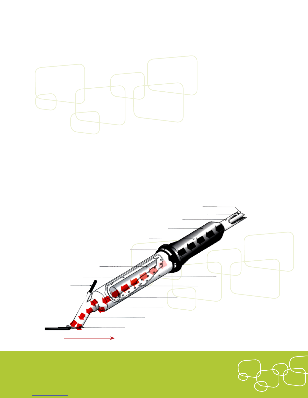
HOW TO SET UP A WELDER:
1. Close valve on air-pressure regulator by pulling upward
on the plastic knob until a clicking sound is heard, and
then proceeding to turn the knob counter clockwise This
will prevent possible damage to the gauge from a sudden
surge of excessive air pressure.
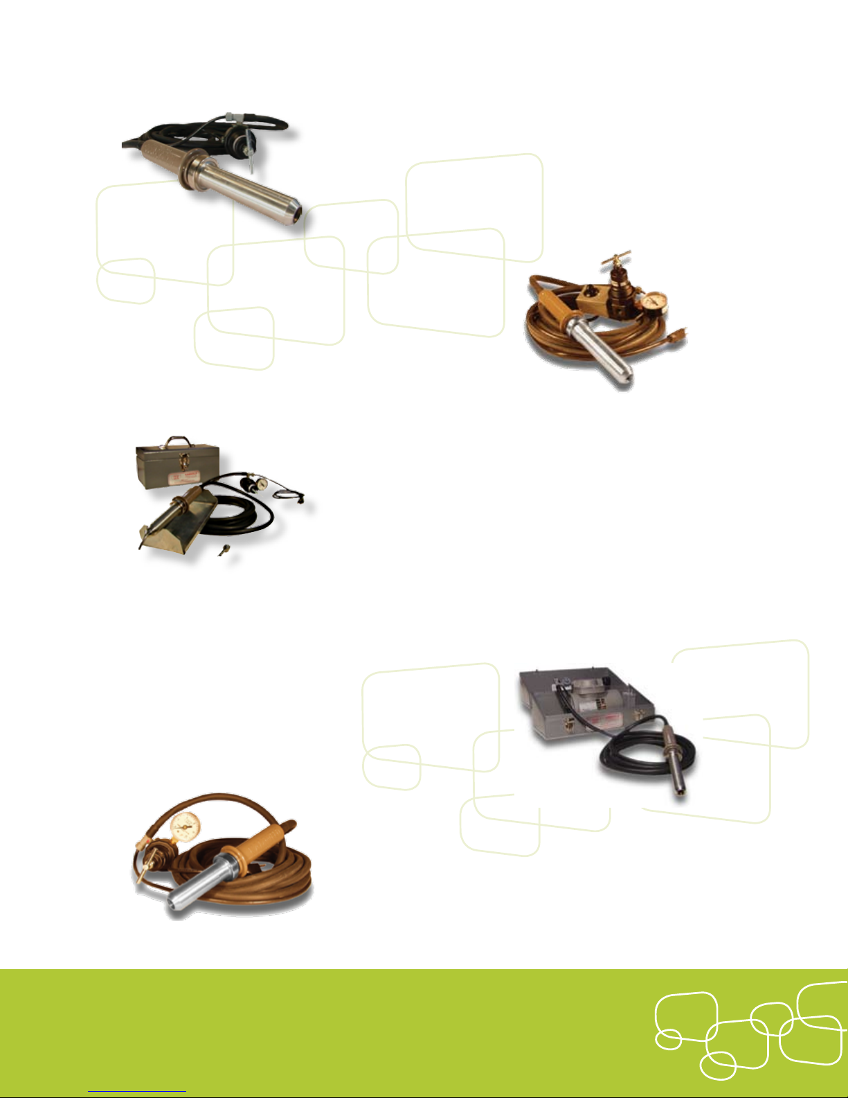
2. Connect the regulator to a supply of either compressed air
(which should be free of oil or moisture) or inert gas. The
Kamweld air-pressure regulator is rated for 200 lbs. (90.72
kg) of line pressure. If inert gas is used, a pressure reduc-
ing is needed (obtainable from a gas supplier).
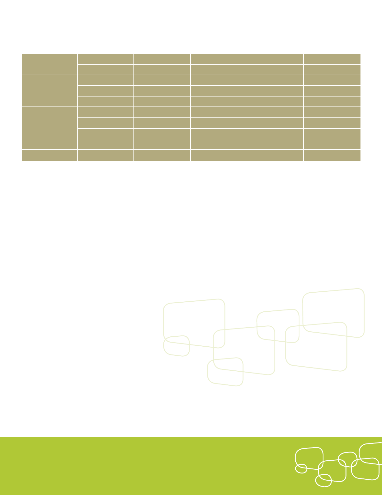
3. Turn the air supply on. The starting air pressure for each
model is indicated in the chart on the next page. Please
note that the heated air temperature depends on the
wattage of the heating element AND the air pressure. The
operating air pressure requires slightly less air. The chart
shows the approximate temperatures obtainable with 120
volt AC supply:
Caution: if the round spanner nut (which holds the barrel to the
handle) becomes too warm to the touch, the gun is overheating. If
this occurs, increase the air pressure immediately, according to the
instructions in the right column. By increasing the air pressure, the
air temperature decreases.
4. Connect the welder to a common 120 volt AC outlet. A
three-prong grounded plug is supplied with each unit and
MUST be used.
5. Allow the welder to warm up at the recommended
STARTING pressure according to the temperature chart on
the following page. It is essential that either air or inert gas
ows through the welder at all times, (from warming up to
cooling o), to prevent burn-out of the heating element
and/or further damage to the gun. AT NO TIME SHOULD
THE ELECTRICITY BE CONNECTED WITHOUT AIR FLOW-
ING THROUGH THE GUN.
6. Select the proper welding tip and install it into the thread-
ed outer barrel with pliers to avoid touching the tip and
barrel while they are hot. After the tip has been installed,
the temperature will increase slightly due to back pressure.
Allow two to three minutes for the tip or outer barrel to
reach the required operating temperature.
7. If you nd the temperature is too high to weld the mate-
rial you are working with, increase the air pressure slightly
until the temperature decreases. If the temperature is too
low for your application, decrease the air pressure slightly
until the temperature rises. When increasing or decreasing
the air pressure, allow at least two or three minutes for the
temperature to stabilize at the new setting. Damage to the
welder or heating element will not occur from too much air
pressure: however, the element can become overheated
by too little air pressure. When decreasing the air pressure
from the recommended starting pressure, never allow the
spanner nut to become too hot to the touch. This is an
indication of overheating. Maximum operating tempera-
ture with the minimum air pressure is obtained when the
spanner nut is only slightly warm to the touch. A partial
clogging of the dirt screen in the regulator or a uctuation
in the line voltage can also cause over or under heating.
5

8. If the threads at the end of the barrel become tight, clean
them with a 9/16”-18 tap. Occasional application of high
temperature grease on the threads (both at the outlet end
of the barrel and on the spanner nut) will prevent seizing
and keep threads free.
HOW TO DISCONNECT THE WELDER:
When welding is completed, disconnect the electricity and
allow the air to ow through the welder for about four to ve
minutes or until the barrel becomes cool enough to touch.
HOW TO CHANGE HEATING ELEMENTS:
Push the end of the barrel against a solid object (such as the
side of a bench). Hold the handle tightly and push inward.
The pressure on the barrel compresses the element spring,
Use the spanner wrench to loosen the spanner nut. Keep the
pressure on the handle and back o the nut all the way by
hand. Hold the barrel and place the complete welder on a
at surface. Remove the barrel and gently pull the element
out of the handle. Grasp the socket at the end of the wire
tightly and jiggle or rock the element while pulling until the
element is completely dislodged from the socket. To reinstall
the element, reverse the above procedure. Turn the element
clockwise (about 1 ½ turns) while pushing the wire gently
back into the handle. This prevents kinking of the wire dur-
ring reinstallation. To reinstall the barrel, reverse the above
procedure.
HOW TO DISASSEMBLE THE HANDLE:
To remove the plastic grip from the handle, remove the
screw at the end of the grip. Slide the grip back over the
hose. Hold the handle rmly and grasp the tail piece and
hose. Use a slight twisting motion while pulling back until it
becomes free. Then the wire and socket can be completely
removed. To reassemble, reverse the above procedure, mak-
ing sure to line up the screw holes in the tail piece and the
handle.
41-HT
43-HS
44-AW
46-RW
47-RW
350 w 2.5 lbs. 6 min. 2 lbs. 600 °F (316 °C)
450 w 3.5 lbs. 6 min. 2.5 lbs. 675 °F (357 °C)
600 w 3 lbs. 6 min. 2.5 lbs. 725 °F (385 °C)
750 w 3.55 lbs. 6 min. 3 lbs. 850 °F (454 °C)
900 w 4 lbs. 7 min. 3 lbs. 900 °F (482 °C)
LOW 300 w 3 lbs. 6 min. 2.5 lbs. 575 °F (301 °C)
MED 400 w 4 lbs. 6 min. 2.5 lbs. 650 °F (343 °C)
HIGH 700 w 4.5 lbs. 6 min. 3 lbs. 825 °F (441 °C)
350 w Pre-Set 5 min. High Setting 650 °F (343 °C)
600 w Pre-Set 5 min. High Setting 800 °F (426 °C)
Cartridge Type
Element Watts
Starting Air Pressure
(Approx.)
Warm-Up Time
(Approx.)
Operating Pressure
(Minimum)
Maximum Air Temp.
Without Tip Installed
(Approx.)
KAMWELD
WelderModel
6

WELDING OPERATIONS:
There are three basic types of plastics welding with hot-air:
Tack Welding, Hand Welding and High-Speed Welding.
TACK WELDING
Tack welding is a shallow fusion of the mating surfaces of
the material. It possesses little tensile strength. It holds the
pieces together until the regular bead is welded. Tack weld-
ing eliminates the need for clamps, jigs and additional
manpower.
For practice welding, prepare the material as follows:
1. Take two pieces of 1/8” thick PVC sheets, each about 2”
wide by 6” long. Bevel one of the long edges of each piece
to about 30º for a total included angle of 60º. Do not
bevel to a feathered edge.
2. Remove all dust and chips. Do not use a solvent. This will
soften the material and result in a poor weld.
3. Clamp one of the beveled pieces at on a work bench with
the bevel pointed upward. Place the other pieces so that
the beveled edges face each other. Install the tacker tip.
Hold the welder upright at an angle of about 80º perpen-
dicular to the surface of the material.
4. Hold the loose PVC piece rmly against the clamped piece.
Touch the point of the tacker tip quickly but rmly along
the mating surfaces, making short (½” to ¾”) tacks at inter-
vals of about 1 ½ to 2” along the joint.
5. Then draw the point of the tacker tip along the entire
joint, fusing the edges together. This operation must be
performed quickly. Hesitation at any point can result in
charred spots that must be removed before further
welding. The two pieces are now fused together with
sucient strength for handling.
HAND WELDING
Hand welding can provide very high tensile strength, if
properly accomplished. It is recommended for welding
KT
KR
7

corners, short runs and small radii. It also provides the begin-
ner with a chance to determine the correct balance of heat
and pressure required to produce a good weld.
1. Install the round tip and allow for warm-up time. Hold the
welder in one hand and weld rod in the other hand.
2. Preheat the base material at the start of the weld by fan-
ning the heat about ½” from the material’s surface.
3. Hold the rod, which has been precut at a 60º angle, per-
pendicular to the joint of the material, and slightly above
the preheated point, with the face of the 60º cut toward
the direction of the weld.
4. Direct the heat to the beveled surface of the material and
the bottom and front surfaces of the rod. Continue the
fanning motion of the tip. Make sure that the air stream is
directed straight to the joint of the rod and beveled area.
When the rod and the base material become shiny and
“tacky”, touch the rod material. They will stick together.
5. Now lean the rod forward in the direction of the weld.
Push the rod down so that the rst part will adhere and not
“skid”. Maintain enough pressure on the rod so that the
softened end of the rod presses into the softened surface
of the material.
Flow lines (see Figure 3a) will appear on sides of the rod.
A small wave of softened material, consisting of fused rod
and base material, will ow in the bevel in front of the rod,
if the pressure is being evenly and constantly applied.
6. Now lean the rod back at a slight angle, away from the
direction of the weld, causing the rod to bend just above
the point where it is owing into the bevel. Maintain the
fanning motion with the welder tip and enough pressure
on the rod while proceeding with the weld.
Generally speaking, the base material will take more
heat than the rod, although the distribution of the heat
necessary can be determined by observation. If the tip is
not kept in motion or if it is held too close, browning or
charring will occur, resulting in an unsatisfactory weld. If
the tip is held too far away or at an incorrect angle, an
uneven weld will occur. If the rod is pushed too hard into
the base material, it will stretch, resulting in a at, highly
stressed weld, which will break if an additional weld is laid
over or abutting it or if it is subjected to routine environ-
mental stress.
Figure 3a. Good and Bad Flow Lines
8

Figure 3b. Good and Bad Welds
7. The weld can be stopped at any time by merely removing
the heat from the weld area. The weld may be continued
from that point with the same rod, or an entirely new start
can be made, using the procedure above.
Figure 4. Types of Welds
8. When the weld is completed, cut the rod o close to the
base material with a knife or a pair of cutting pliers.
Inside Corner Welds
Outside Corner Welds
Double “V” Butt Welds
Edge Welds
Single “V” Butt Welds
Corner and Fillet Welds
Welds join and overlap over bevel
Good root pass has good penetration
Poor root pass , no penetration, cold weld
Note lacking in overlap in bevel.
Poor root pass , no penetration, cold weld
Burned root pass and material
9
Triangular
Round

HIGH-SPEED WELDING
The principle of high-speed welding incorporates the
basic methods utilized in hand welding with specially
designed and patented tools. Here too, the requirements
for constant heat and pressure must be fullled. The
accelerated rate of speed in high-speed welding is
possible because both the rod and the base material are
preheated before they reach the fusion point. A round
or triangular rod is preheated in a tube, while the base
material is preheated by the hot air stream from a vent
in the underside of the welding tip.
The necessary pressure is no longer provided by holding
the rod in the hand. Instead, a shoe on the end of the
tool furnishes the necessary pressure and, at the same
time, smooths out the rod for uniform appearance and
higher tensile strength. Gentle pressure on the rod
results in better control of the weld.
The conventional hand welding method now becomes a
faster and more uniform operation. Once started, the rod is
fed automatically into the preheating tube by the motion of
the welder being pulled along the joint. The Kamweld high-
speed tools automatically give constant balance of heat and
pressure.
Welding Positions:
1.
Start of Weld
2.
Actual Welding
3.
End of Weld
Figure 5. High-Speed Welding with round or
triangular rod.
1. Select and install the proper size high-speed tip for the ap-
propriate size welding rod. Allow for warm-up time.
2. Grasp the welder rmly and hold it in an upright posi-
tion, with the point of the high-speed tip approximately
½” above base material, directly over the starting point of
the weld. Insert the rod into the welding tube and hold it
there until the base
material turns shiny and starts to soften.
3. Push the rod down until it sticks to the base material.
4. Continue exerting downward pressure on the rod, which
will then bend and lower the shoe to the rod. The shoe of
the tip will rest on top of the exposed part of the rod (see
Figure 5, illustration 1).
123
Welding Positions:
1.
Start of Weld
2.
Actual Welding
3.
End of Weld
10

5. While continuing to exert moderate pressure with the
shoe, lean the welder to about 60º toward the operator
and start pulling the welder in the same direction of the
weld, at the same time helping the rod into the preheating
tube with light hand pressure (see Figure 5, illustration 2).
This technique requires practice. If the weld progresses too
slowly, discoloration and charring will occur, and the rod
will buckle in the feed tube. If it progresses too quickly, a
cold weld will occur.
6. Continuously observe the condition of the welding rod as
it appears under the shoe as the weld progresses. Uniform
ow lines should be visible along both sides of the rod,
without discoloration or charring.
7. After completion of the weld, the rod can be cut o in two
ways:
a) Withdraw the welder completely so that any
remaining welding rod will slide out of the tube.
The rod can then be cut with a knife or cutting
pliers as close as possible to the end of the weld.
DO NOT allow the rod to lift at the end of the
weld.
b) Bring the welder quickly to an upright position
and push down hard with the point of the shoe.
This action cuts the rod at the end of the weld.
The remaining rod is pulled out of the tube by
hand (see Figure 5, illustration 3).
HIGH-SPEED WELDING FOR PLASTICIzED STRIPS
(CORNER OR FLAT STRIPS)
Follow the same procedure as for round or triangular rod
high-speed welding as previously described, except:
1. Precut the strips to required length to complete the weld.
2. Start the weld by tamping the shoe section of the strip in
the direction of the weld. Do not drag for the rst inch of
the weld until the strip appears rm. Then continue weld-
ing with proper downward pressure and speed, showing
slight ow lines along both sides of the strip. If performed
properly, slight ow lines along both sides of the strip will
appear
Figure 6. High-Speed Welding with Plasticized Strips
NOTE:
If the weld progresses too slowly, the strip will soften
excessively and the shoe will stretch the strip. A quick recov-
ery can be made by immediate motion, such as in the start of
a weld, proceeding in the direction of weld at the same time.
Plasticized Strip
Base Material
Flow Lines
High Speed
Tool
Position of
Welder
KS-3
11

Kamweld Technologies, Inc.
90 Access Road, Norwood, MA 02062
Telephone : 781 762 6922
Fax : 781 762 0052
WARRANTY
Kamweld Technologies, Inc. (the “manufacturer” or “Kamweld”) warrants its products and repair services to be free from defects in materials
and workmanship under limitations of normal operation by the purchaser, as prescribed in the instructions furnished to the purchaser, for
a period of 90 days from the date of purchase. Except as set forth herein, Kamweld makes no warranty respecting the merchantability of its
products or their suitability or tness for a particular purpose or use.
Kamweld shall not be held liable for any damage to person or property resulting from any breach of this warranty, nor be responsible for any
work done or repairs made by others, unless authorized in writing by the manufacturer. In no event shall Kamweld be held liable for inciden-
tal, special, or consequential damages. This warranty is limited to the replacement of the product for the period set forth above.
This warranty shall become void if the purchaser modies the product, uses the product in a manner that in the manufacturer’s judgment
exceeds its design capability, or if evidence of negligent or abusive operation is present.
12

KS-1B
For low-density polyethylene,
5/32” round rod
Kamweld
STAINLESS STEEL
Tools & Tips
KS-1-8-A
For polypropylene, 1/8”
round rod
KS-1
For Type I and II PVC, 5/32”
round rod
KS-1-OLD
Longer version of KS-1
KS-1C
For polypropylene, high-
density polyethylene and
other high-temperature
thermoplastics, 5/32”
round rod
KS-2C
For polypropylene, high-
density polyethylene and
other high-temperature
thermoplastics, 3/16”
round rod
KS-3
Flat and corner strip for tank
lining, 5/8” to 3/4”, plasticized
PVC
KS-4A
Flat and corner strip for tank
lining, 1”, plasticized PVC
KS-6
For Type I and II PVC, 1/4”
round rod
KST-6C
For polypropylene, high-
density polyethylene and
other high-temperature
thermoplastics, 1/4” round rod
KST-2
For triangular PVC rod,
equivalent to 3/16”
KST-2C
For triangular polypropylene
rod, equivalent to 3/16”
KST-3
For triangular PVC rod,
equivalent to 1/4”
KST-3C
For triangular polypropylene
rod, equivalent to 1/4”
KR
Round Tip for hand welding
KS-1-8
For Type I and II PVC, 1/8”
round rod
KS-2B
For low-density polyethylene,
3/16” round rod
KST-1A
For triangular polypropylene
rod, equivalent to 1/8”
KF-1
Flat Tip, 5/8” to 3/4” wide for
hand welding
KF-2
Flat Tip, 1” wide for
hand welding
KV-1
Also known as the “V” Tip, 5/8”
to 3/4” wide for hand welding
KV-2
“V” Tip, 1” wide for
hand welding
KS-2
For Type I and II PVC, 3/16”
round rod
KST-1
For triangular PVC rod,
equivalent to 1/8”
KRL
Round Tip, extra long for
hard-to-reach areas
for hand welding
KT
Tacker Tip for hand welding
13
Visit www.kamweld.com for more information or to place an order today.

Kamweld
STAINLESS STEEL
Welding Products
KHD
The KAMWELD Heating Device is used for bending plastic
sheets of dierent widths and lengths. This bending device
heats thermoplastic sheets in order to make straight-line
bends that are necessary when fabricating items such as
hoods, ducts, tanks, displays, signs and many other items.
KHD consists of two rectangular aluminum heating bars,
two control switches for adjusting the temperature and
two aluminum base units. Each heating bar contains
an electric heating element that provides uniform heat.
Four sizes are available: 28”, 54” , 96” & 144”.
44-AWC
300 and 400, or 700 watt
combination for model 44-AW
HSC
600, 750, and 900 watt for
model 43-HS
RWC
350 watt for model 46-RW and
600 watt for model 47-RW
HTC & HSC
350 and 450 watt for model
41-HT and model 42-TM
KHAG
The KAMWELD Hot Air Gun is supplied complete with an
air regulator and pressure gauge, a 2” long, 5/8” diameter
stainless steel anged round tip with check-nut and 5 ‘ of
insulated cable. A stainless steel wrap-around mounting
bracket permits permanent mounting to existing equipment,
and the gun may be grounded through the mounting
bracket. Two models available. Both models are designed
for use with 115 volts AC, but they can be supplied for a
230 volt system.
Kamweld Technologies, Inc.
Kamweld Technologies, Inc. is a leading provider of plastic welding products, industrial
hot air guns, plastic sheet bending devices and accessories. For nearly 50 years, the
Kamweld name has stood for superior products, rugged durability and highly competitive
prices. All of our products are developed, manufactured, tested and packaged within
the USA, resulting in consistent quality and rapid turnaround time.
14
Visit www.kamweld.com for more information or to place an order today.
Table of contents
Other KAMWELD Welding System manuals
Popular Welding System manuals by other brands

STAMOS
STAMOS S-ALU 220 UK user manual

STAMOS
STAMOS S-MIG 250 user manual

Miller Electric
Miller Electric Gas Cylinder Rack owner's manual

Longevity
Longevity TIGWELD 250 EX operating manual

Campbell Hausfeld
Campbell Hausfeld GW4502 Operating instructions and parts manual

Miller
Miller Syncrowave 350 LX owner's manual

Mweld
Mweld MW120mini-PRO instruction manual

Lincoln Electric
Lincoln Electric K397 Series Operator's manual

Miller
Miller AMD-4 owner's manual

Lincoln Electric
Lincoln Electric CITOTIG 200 AC/DC Operator's manual

Baileigh Industrial
Baileigh Industrial WP-1800B Operator's manual

Sua
Sua ionCut 40 PADV Operation manual