Sua ionCut 40 PADV User manual
ionCut 40 PADV
Copyright © Mundaka Welding & Gases, Inc.
ionCut 40 PADV
INVERTER IGBT – AIR PLASMACUTTER
OPERATION MANUAL
IMPORTANT: Read this Owner’s Manual Completely before attempting to use this
equipment. Save this manual and keep it handy for quick reference. Pay particular
attention to the safety instructions we have provided for your protection. Contact your
distributor if you do not fully understand this manual.

ionCut 40 PADV
Copyright © Mundaka Welding & Gases, Inc.
2
CONTENT
1. SAFETY........................................................................................................ 3
2. Technology Parameters.............................................................................. 5
2.1 Parameters.................................................................................................... 5
3. Installation ................................................................................................... 6
3.1 Unpacking..................................................................................................... 6
3.2 Input Power Connections............................................................................ 6
3. 3 Gas Connections......................................................................................... 6
4. Operation..................................................................................................... 7
4.1 Layout Of The FrontAnd Rear Panel ......................................................... 7
4.2 Cutting Preparation..................................................................................... 7
4.3 Cutting Operation........................................................................................ 8
5. Maintenance ................................................................................................ 8
5.1 Cutting gun maintenance ............................................................................ 8
5.2 Troubleshooting........................................................................................... 9
5.3 Electrical principle drawing........................................................................11

ionCut 40 PADV
Copyright © Mundaka Welding & Gases, Inc.
3
1. SAFETY
OPERATION AND MAINTENANCE OF PLASMA ARC EQUIPMENT CAN
BE DANGEROUSAND HAZ-ARDOUS TO YOUR HEALTH.
Plasma arc cutting produces intense electric and magnetic emissions that
may interfere with the proper function of cardiac pacemakers, hearing aids,
or other electronic health equipment. Persons who work near plasma arc
cutting applications should consult their medical health professional and the
manufacturer of the health equipment to deter- mine whether a hazard
exists.
To prevent possible injury, read, understand and follow all warnings, safety
precautions and instructions before using the equipment.
GASESAND FUMES
Gases and fumes produced during the plasma cutting process can be
dangerous and hazardous to your health.
• Keep all fumes and gases from the breathing area. Keep your head out of
the cutting fume plume.
• Use an air-supplied respirator if ventilation is not adequate to remove all
fumes and gases.
• The kinds of fumes and gases from the plasma arc depend on the kind of
metal being used, coatings on the metal, and the different processes. You
must be very careful when cutting any metals which may contain one or
more of the following:Antimony, Chromium, Mercury, Beryllium, Arsenic,
Cobalt, Nickel, Lead, Barium, Copper, Selenium, Silver, Cadmium,
Manganese, and Vanadium. Always read the Material Safety Data Sheets
(MSDS) that should be supplied with the material you are using. These
MSDSs will give you the information regarding the kind and amount of
fumes and gases that may be dangerous to your health.
• Use special equipment, such as water or down draft cutting tables, to
capture fumes and gases.
• Do not use the plasma torch in an area where combustible or explosive
gases or materials are located.
• Phosgene, a toxic gas, is generated from the vapors of chlorinated
solvents and cleansers. Remove all sources of these vapors.
ELECTRIC SHOCK
Electric Shock can injure or kill. The plasma arc process uses and
produces high voltage electrical energy. This electric energy can cause
severe or fatal shock to the operator or others in the workplace.
• Never touch any parts that are electrically “live” or “hot.”
• Wear dry gloves and clothing. Insulate yourself from the work piece or
other parts of the cutting circuit.
• Repair or replace all worn or damaged parts.
• Extra care must be taken when the workplace is moist or damp.

ionCut 40 PADV
Copyright © Mundaka Welding & Gases, Inc.
4
• Disconnect power source before performing any service or repairs.
• Read and follow all the instructions in the Operating Manual.
FIREAND EXPLOSION
Fire and explosion can be caused by hot slag, sparks, or the plasma arc.
• Be sure there is no combustible or flammable material in the workplace.
Any material that cannot be removed must be protected.
• Ventilate all flammable or explosive vapors from the workplace.
• Do not cut or weld on containers that may have held combustibles.
• Provide a fire watch when working in an area where fire hazards may
exist.
• Hydrogen gas may be formed and trapped under aluminum workpieces
when they are cut underwater or while using a water table. DO NOT cut
aluminum alloys underwater or on a water table unless the hydrogen gas
can be eliminated or dissipated. Trapped hydrogen gas that is ignited will
cause an explosion.
NOISE
Noise can cause permanent hearing loss. Plasma arc processes can
cause noise levels to exceed safe limits. You must protect your ears from
loud noise to prevent permanent loss of hearing.
• To protect your hearing from loud noise, wear protective ear plugs and/or
ear muffs. Protect others in the workplace.
• Noise levels should be measured to be sure the decibels (sound) do not
exceed safe levels
PLASMAARC RAYS
Plasma Arc Rays can injure your eyes and burn your skin. The plasma arc
process produces very bright ultra violet and infra-red light. These arc rays
will damage your eyes and burn your skin if you are not properly protected
• To protect your eyes, always wear a cutting helmet or shield. Also
always wear safety glasses with side shields, goggles or other protective
eye wear.
• Wear cutting gloves and suitable clothing to protect your skin from the arc
rays and sparks.
• Keep helmet and safety glasses in good condition. Replace lenses when
cracked, chipped or dirty.
• Protect others in the work area from the arc rays. Use protective booths,
screens or shields.
ionCut 40 PADV
Copyright © Mundaka Welding & Gases, Inc.
5
2. Technology Parameters
2.1 Parameters
M
Parameters
ionCut 40 PADV
110V INPUT
220V INPUT
Inputpower
single-phase,110V±10%,
50/60Hz
single-phase,230V±10%,
50/60Hz
Rated input current(A)
37(110V)
34(220V)
Rated input power(KW)
3.7(110V)
5.2(220V)
Adjustment range of current
(A)
20~30(110V)
20~40(220V)
Max no-load voltage(V)
200
220
Duty cycle(40°C,10 minutes)
50%(110V)
50%(220V)
Severance cut for Carbon
steel (mm)
≤14
≤25
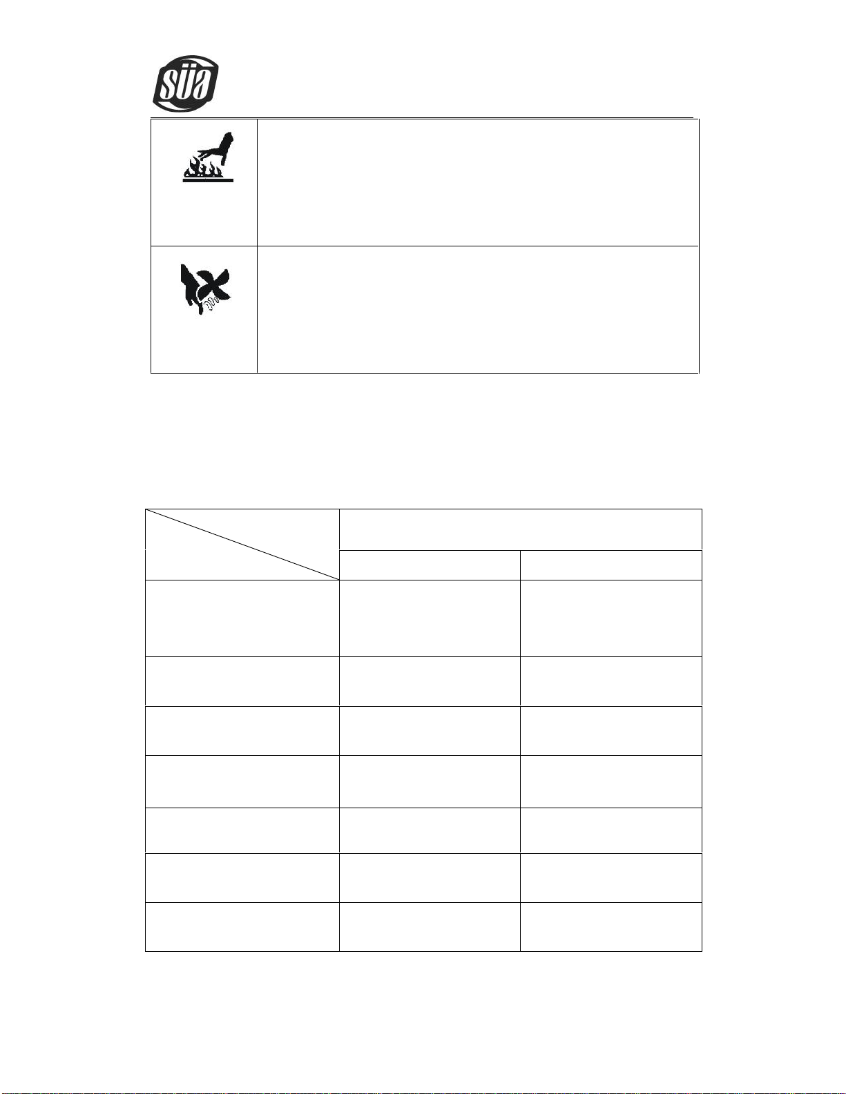
Hot parts can lead to burn.
Do not touch the hot parts.
Please use the torch after cooling or use the welding blow lamp.
The Rotating parts may be dangerous.
Far away from rotating parts. (like fan)
Keep the parts of machine in the safe position.

ionCut 40 PADV
Copyright © Mundaka Welding & Gases, Inc.
6
Production cut for Carbon
Steel (mm)
≤12
≤16
Production cut for Stainless
Steel (mm)
≤12
≤18
Production cut for Aluminum
(mm)
≤8
≤14
Production cut for Copper
(mm)
≤6
≤8
Weight(Kg)
7.6
Note: The above parameters are subject to change with the improvement of machines.
3. Installation
3.1 Unpacking
1. Use the packing lists to identify and account for each item.
2. Inspect each item for possible shipping damage. If damage is evident, contact your
distributor and / or shipping company before proceeding with the installation.
3.2 Input Power Connections
Note: Check your power source for correct voltage before plugging in or connecting the unit
3. 3 Gas Connections
a) Connecting Gas Supply to Unit
b) Connect the gas line to the inlet port of the gas filter on the rear panel.
ionCut 40 PADV
Copyright © Mundaka Welding & Gases, Inc.
7
4. Operation
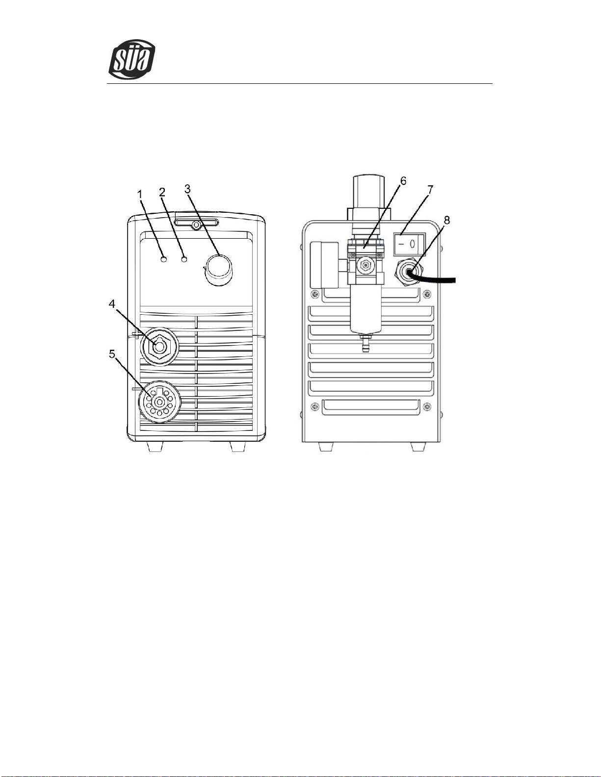
4.1 Layout Of The Front And Rear Panel
ionCut 40 PADV
1. Power pilot lamp turn on power, the lamp on
2. Over-current, over-heat alarm when over-heat, over-current, the lamp would be on.
3. Cutting current regulator it is used to regulate the current when cutting.
4. Positive output cable connected to the work piece
5. Cutting gun connector
6. Compressed air connector
7. Power switch turn on or off the power source
8. Power cable connected to the appreciate power supply
4.2 Cutting Preparation
1. Tightly connect the power cable to electrical socket outlet (the input voltage, refer to
the section 2 technology parameters)
2. Connect the air pipe to the air supply equipment, the earth cable to the work piece

ionCut 40 PADV
Copyright © Mundaka Welding & Gases, Inc.
8
3. Turn on the power switch, the power source lamp on.
4. Ready for cutting operation.
4.3 Cutting Operation
1. Turn on the power source.
2. Press on the cutting switch.
3. Pre-gas for 2 seconds
4. Ignite the pilot arc.
5. Shift to the work piece, the pilot arc change into cutting arc.
6. Perform the cut.
7. The torch leaves the work piece, the cutting arc change into pilot arc.
8. Loose the cutting torch switch.
9. Arc extinguished.
10. Post-gas for 30 seconds.
5. Maintenance
5.1 Cutting gun maintenance
Warning:
1. Check the consumable parts, if damaged, replace them.
2. Turn off the power source before check or remove cutting gun parts
Note: When operating the torch in a normal condition, a small amount of gas vents through the
gap between the shield cup and the torch handle, do not attempt to over tighten the shield cup
as irreparable damage to internal components may result
ionCut 40 PADV
Copyright © Mundaka Welding & Gases, Inc.
9
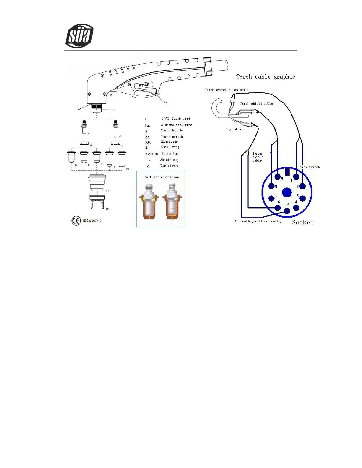
PT60 Plasma Torch
5.2 Troubleshooting
WARNING
There are extremely dangerous voltage and power levels present inside this unit. Do not
attempt to diagnose or repair unless you have had training in power electronics measurement
and troubleshooting techniques.
1. Power lamp and temperature lamp on.
a) Air flow blocked, check for blocked air flow around the unit and correct condition.
b) Fan blocked, check and correct condition.
c) Unit is overheated, let unit cool down for at least 5 minutes. Make sure the unit has not
been operated beyond Duty Cycle limit, refer to technology parameters in Section 2.
d) Faulty components in unit, return for repair or have qualified technician repair per
Service Manual.
2. Torch fails to ignite the arc when torch switch is activated.
a) Faulty torch parts, inspect torch parts and replace if necessary.
b) Gas pressure too high or too low,adjust to proper pressure.
c) Faulty components in unit, return for repair or have qualified technician repair per

ionCut 40 PADV
Copyright © Mundaka Welding & Gases, Inc.
10
Service Manual.
3. No cutting output; Torch activated, power source on; Gas flows; Fan operates.
a) Torch not properly connected to power supply, check that torch leads are properly
connected to power supply.
b) Work cable not connected to work piece, or connection is poor, make sure that work
cable has a proper connection to a clean, dry area of the work piece.
c) Faulty components in unit, return for repair or have qualified technician repair per
Service Manual.
d) Faulty Torch, return for repair or have qualified technician repair.
4. Low cutting output
a) Incorrect setting of CURRENT (A) control, check and adjust to proper setting.
b) Faulty components in unit, return for repair or have qualified technician repair.
5. Difficult Starting
a) Worn torch parts (consumables), shut off input power. Remove and inspect torch shield
cup, tip and electrode. Replace electrode or tip if worn; replace shield cup if excessive
spatter adheres to it.
6. Arc shuts off during operation; arc will not restart when torch switch is activated.
a) Power Supply is overheated (OC/OT lamp on), let unit cool down for at least 5 minutes.
Make sure the unit has not been operated beyond Duty Cycle limit. Refer to Section 2
for duty cycle specifications.
b) Gas pressure too low, check source for at least 4bar/60psi; adjust as needed. It is need
to open the machine cover.
c) Torch consumables worn, check torch shield cup, tip, starter element, and electrode;
replace as needed.
d) Faulty components in unit: return for repair or have qualified technician repair per
Service Manual.
7. No gas flow; the power lamp on; Fan operates.
a) Gas not connected or pressure too low,check gas connections. Adjust gas pressure to
proper setting.
b) Faulty components in unit, return for repair or have qualified technician repair.
8. Torch cuts but low quality
a) Current (A) control set too low, increase current setting.
b) Torch is being moved too fast across work piece, reduce cutting speed.
c) Excessive oil or moisture in torch, hold torch 1/8 inch (3 mm) from clean surface while
purging and observe oil or moisture buildup (do not activate torch). If there are
contaminants in the gas, additional filtering may be needed.

ionCut 40 PADV
Copyright © Mundaka Welding & Gases, Inc.
11
5.3 Electrical principle drawing
Table of contents
Other Sua Welding System manuals


Popular Welding System manuals by other brands

Miller Electric
Miller Electric SWINGER 180 Installation, operation & maintenance manual

EWM
EWM SATURN MIG 200 operating manual

Hypertherm
Hypertherm Powermax1100 Operator's manual

Inteco
Inteco HARRIER 280 instruction manual

Magmaweld
Magmaweld Monostick 200i user manual

Blue Hawk
Blue Hawk FLUX-MIG 100 SGY-WELDER1 user manual


