Amigo — Manual 2.4 Autopilot Lateral Modes
V. . . stands for vertical speed. Same logic as for IAS applies also here. If
current vertical speed is within limits, the light is green, close to limits
the light becomes yellow (amber) and outside limits the light is red.
R. . . stands for roll angle. Again, green, yellow and red lights are shown.
P. . . stands for pitch angle. It can be green, yellow or red.
When any of the above mentioned parameters is red and autopilot is en-
gaged, the autopilot refuses to take control. Also, when AP is active and
any of the status parameters becomes red, the autopilot will automatically
disengage both servo motors. An error window is shown, which explains why
the autopilot is not accessible.
Please refer to the Autopilot manual for more details on how to set the pa-
rameter limits.
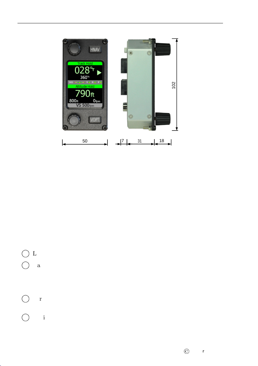
2.4 Autopilot Lateral Modes
Amigo consists of two lateral modes: track hold (TRK) and horizontal naviga-
tion (HNAV). Default lateral mode is the track hold mode, which is displayed
every time Amigo powers up.
To activate TRK mode, rotate the TRK knob – this will change the
reference track and immediately active the track hold mode.
To activate horizontal navigation mode, short press the HNAV button.
The AP will now follow horizontal navigation from some other device
(Nesis or Aetos are required).
2.4.1 Track Hold Mode – TRK
In short, TRK engages roll servo motor to maintain selected reference track.
When a TRK mode is inactive the first increment/decrement of the TRK knob
sets the current track value for the reference and automatically engages roll
servo motor. Any following rotation of the TRK knob changes the reference
heading value:
Reference track value can take values from 1 to 360◦with 1◦resolution.
Rotating the TRK knob clockwise increments the reference track.
10
©
Kanardia 2020