K&N Fuel injection perfomance kit Generation 2 User manual

57-2544
NOTE: FAILURE TO FOLLOW INSTALLATION INSTRUCTIONS AND NOT USING THE PROVIDED HARDWARE
MAY DAMAGE THE INTAKE TUBE, THROTTLE BODY AND ENGINE.
1. Turn off the ignition and disconnect the negative
battery cable.
NOTE: Disconnecting the negative battery cable
erases pre-programmed electronic memories.
Write down all memory settings before
disconnecting the negative battery cable. Some
radios will require an anti-theft code to be
entered after the battery is reconnected. The
anti-theft code is typically supplied with your
owner’s manual. In the event your vehicles’
anti-theft code cannot be recovered, contact an
authorized dealership to obtain your vehicles
anti-theft code.
TO START:
NOTE: This kit was not designed
to t vehicles with a body lift.
FORD
1999-02 Crown Victoria
V8-4.6L
Description Qty. Part #
A hose clamp #44 2 08577
B silicone hump hose 1 087121
C intake tube (CU) 1 087088
D vent hose 3/4"id long 1 08471
E vent hose 5/8" long 1 08538
F hose clamp #48 3 08601
G bolt 6mm fha 1 08376
H saddle bracket 1 078855
I grommet 1 08064
J cup washer 1 08180
K silicone hose 1 08690
L nut 6mm nylock 8 07553
Mwasher 1/4" at 11 08275
N large "L" bracket 1 070602
O edge trim 42"L 1 102499
P heat shield 1 074001
Q bracket 1 07163
R bolt 6mm-1.00 x 10mm 2 07863
S bolt 6mm-1.00 x 16mm 1 07703
T large "L" bracket 1 07093
U small "L" bracket 1 07879
V mass air sensor gasket 1 09330
W silicone adapter #200 1 08831
X bolt allen 1.00 x 25mm 4 07859
Y hose clamp #104 1 08697
Zlter charger 1 RF-1041
PARTS LIST:
TOOLS NEEDED:
Flat Blade Screwdriver
short extension
10mm Socket
11mm socket
5mm Allen Wrench
1/4 ratchet
5/32 Allen
1/4 extension
10mm wrench
8mm socket
Ratcht
Drill
3/4 drill bit
2. Loosen and remove the bolt that retains the
engine cover to the engine with a 1/4 extension,
then remove engine cover.
3. Disconnect the mass air sensor electrical
connection.
4. Disconnect the temp sensor elctrical connection.
Note: Not all vehicles come with external temp
sensors.
5. Disconnect the crank case vent and idle air
hoses as shown.
6. Loosen the hose clamp at the throttle body and
at the mass air sensor then remove the stock air
intake tube as shown.

INSTALLATION INSTRUCTIONS
Continued
7. Release the 2 clips which reatins the airbox lid
then remove the lid from the vehicle.
8. Remove the three nuts that retain the airbox
bottom to vehicle.
9. Remove airbox bottom from vehicle as shown.
NOTE: K&N Engineering, Inc., recommends
that customers do not discard factory air
intake.
10. Remove the 8mm bolt that retains the radiator
fan shroud to radiator.
11. Install the provided bracket (07879) onto
radiator with the provided hardware.
12. Install the two provided brackets onto the
factory rubber mounted studs with the provided
hardware.
Note: Install bracket (07093) onto the lower
rubber mounted stud.
13. Install edge trim onto heat shield as shown.
Trim if needed.
14. Install the heat shield into vehicle and attach to
the two outter brackets.
15. Using the provided hardware, assemble the
saddle bracket assembly as shown.
16. Install the saddle bracket assembly onto the
heat shield as shown.
17. On vehicles that come with external temp
sensor drill out the drill point with a 3/4 drill, then
install the provided grommet as shown.
18. Install the provided silicone hump hose
(087121) onto the K&N®intake tube with the
provided hose clamps.
19. Install the K&N®intake onto the throttle body
and line it up with saddle bracket assembly.
Note: Do not tighten completely.
20. Remove the four bolts that retain the mass air
sensor to the airbox lid, then remove the mass air
sensor from lid.
21. On vehicles that come equipped with an
external temp sensor, twist counter clockwise to
remove from airbox lid.
22. Assemble the lter adaptor onto the mass air
sensor with the provided hardware as shown.
23. Install the silicone hose (08690) onto the mass
air sensor with provided hose clamps as shown.

* FREE K&N® decal To register your warranty, please see us online at knlters.com/register. FREE K&N®decal *
INSTALLATION INSTRUCTIONS
Continued
1. Start the engine with the transmission in neutral
or park, and the parking brake engaged. Listen for
air leaks or odd noises. For air leaks secure hoses
and connections. For odd noises, find cause and
repair before proceeding. This kit will function
identically to the factory system except for being
louder and much more responsive.
2. Test drive the vehicle. Listen for odd noises or
rattles and x as necessary.
3. If road test is ne, you can now enjoy the added
power and performance from your kit.
4. K&N Engineering, Inc., requires cleaning the
intake system’s air lter element every 100,000
miles. When used in dusty or off-road
environments, our lters will require cleaning more
often. We recommend that you visually inspect
your lter once every 25,000 miles to determine
if the screen is still visible. When the screen is no
longer visible some place on the lter element, it is
time to clean it. To clean and re-oil, purchase our
lter Recharger®service kit, part number 99-5050
or 99-5000 and follow the easy instructions.
ROAD TESTING:
32. It will be necessary for all K&N® high ow intake
systems to be checked periodically for realignment,
clearance and tightening of all connections.
Failure to follow the above instructions or proper
maintenance may void warranty.
• 1455 CITRUS ST., P.O. BOX 1329, RIVERSIDE, CA., U.S.A. 92502 • TECH SERVICE 800-858-3333 • FAX 951-826-4001
• e-mail: tech@knlters.com® • WWW: http://www.knlters.com®
31. The C.A.R.B. exemption sticker, (attached),
must be visible under the hood so that an
emissions inspector can see it when the vehicle
is required to be tested for emissions. California
requires testing every two years, other states may
vary.
30. Reconnect the vehicle’s negative battery cable.
Double check to make sure everything is tight and
properly positioned before starting the vehicle.
17727D
5/07/14
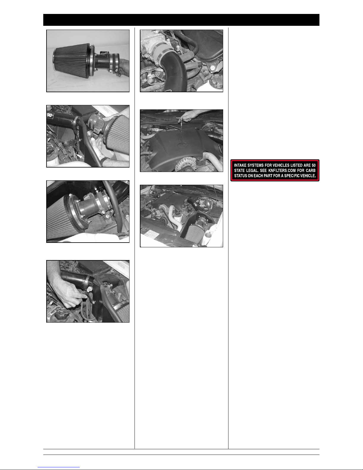
24. Install the ltercharger onto the mass air
assembly as shown.
25. Reconnect the mass air sensor electrical
connection as shown.
26. Install the mass air assembly onto the intake
tube and adjust for best t before tighting hose
clamps.
27. On vehicles with external temp sensor, install
the temp sensor onto the intake tube then re-
connect the electrical connection.
28. Reconnect the crank case vent and idle air
hose onto the new intake tube with the provided
silicone hoses as shown.
29. Re-install the engine cover that was removed
in step 2.
This manual suits for next models
1
Popular Car Spares manuals by other brands

PPE
PPE Oil Pan installation guide

Audiosystem
Audiosystem R EVO Series user manual

Aero-motive
Aero-motive 13006 installation instructions

ADD
ADD 2015 – Current Chevy Colorado & GMC Canyon installation instructions

ADD
ADD 2015 – Current Chevy Colorado & GMC Canyon ADD... installation instructions

WABCO
WABCO ABS Maintenance manual