KanexPro SP-HDBT1X4 Technical manual

SP-HDBT1X4
4K HDBaseT Splitter 1x4
With PoE
All Rights Reserved
Version: 4K HDBaseT Splitter 1x4 with PoE_2014V1.0

SP-HDBT1X4
SAFETY PRECAUTIONS
To insure the best from the product, please read all instructions carefully before using
the device. Save this manual for further reference.
!Unpack the equipment carefully and save the original box and packing material for
possible future shipment
!Follow basic safety precautions to reduce the risk of fire, electrical shock and injury
to persons.
!Do not dismantle the housing or modify the module. It may result in electrical shock
or burn.
!Using supplies or parts not meeting the products’ specifications may cause damage,
deterioration or malfunction.
!Refer all servicing to qualified service personnel.
!To prevent fire or shock hazard, do not expose the unit to rain, moisture or install this
product near water.
!Do not put any heavy items on the extension cable in case of extrusion.
!Do not remove the housing of the device as opening or removing housing may
expose you to dangerous voltage or other hazards.
!Install the device in a place with fine ventilation to avoid damage caused by
overheat.
!Keep the module away from liquids.
!Spillage into the housing may result in fire, electrical shock, or equipment damage. If
an object or liquid falls or spills on to the housing, unplug the module immediately.
!Do not twist or pull by force ends of the optical cable. It can cause malfunction.
!Do not use liquid or aerosol cleaners to clean this unit. Always unplug the power to
the device before cleaning.
!Unplug the power cord when left unused for a long period of time.
!Information on disposal for scrapped devices: do not burn or mix with general
household waste, please treat them as normal electrical wastes.

SP-HDBT1X4
NOTICE:
1. Pictures shown in this manual are for reference only; different model and
specifications are subject to real product.
2. The item PoE/ PoC is short for Power over Ethernet or Cable.
3. The receiver works with HDBaseT Splitter can only be HDMI Twisted Pair PoC
Receiver.
4. The item “far-end” means the device (e.g. display device, 3rd party RS232 device
etc.) connected with HDMI Twisted Pair PoC Receiver.
This manual is for operation instruction only, not for any maintenance usage. The
functions described in this version are updated till July 2014. Any changes of
functions and parameters since then will be informed separately. Please refer to
the dealers for the latest details.
All rights reserved. No part of this publication may be copied or reproduced without
the prior written consent.
All product function is valid till 2014-07-25.

SP-HDBT1X4
Contents
1. Introduction.................................................................................................................. 1!
1.1 Introduction to SU4HT ....................................................................................... 1!
1.2 Features............................................................................................................. 1!
1.3 Package List ...................................................................................................... 1!
2. Panel Description ........................................................................................................ 2!
2.1 Front Panel ........................................................................................................ 2!
2.2 Rear Panel ......................................................................................................... 3!
3. System Connection ..................................................................................................... 4!
3.1 Usage Precautions............................................................................................. 4!
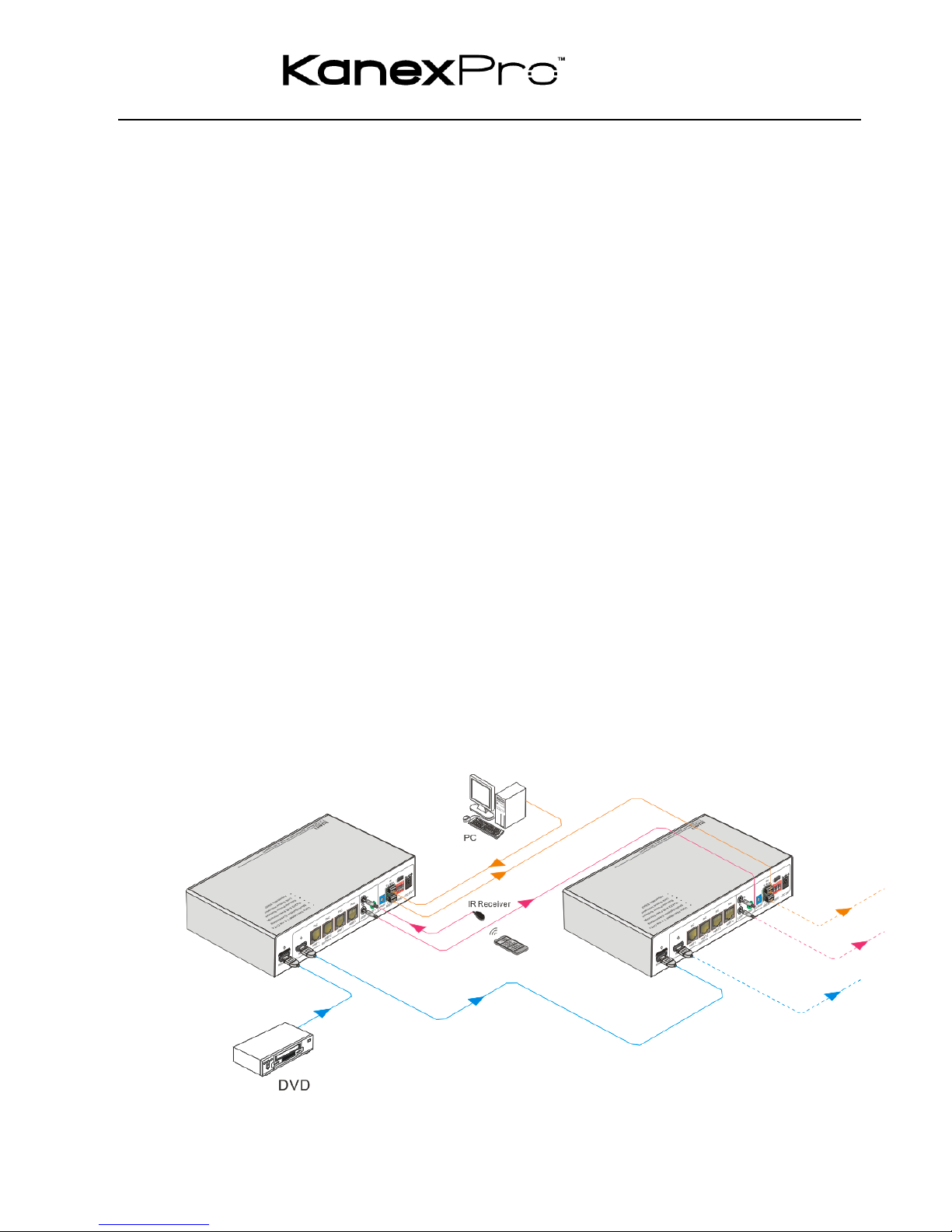
3.2 System Diagram ................................................................................................ 5!
3.3 Connection Procedure ....................................................................................... 5!
3.4 Cascade Connection.......................................................................................... 6!
3.4.1 Cascade AV Signal.................................................................................. 6!
3.4.2 Cascade Control Signal ........................................................................... 6!
3.5 Twisted Pair Cable Connection.......................................................................... 8!
4. Control Modes............................................................................................................. 8!
4.1 IR Control........................................................................................................... 8!
4.1.1 Control far-end device from local............................................................. 8!
4.1.2 Control local device from remote ............................................................. 9!
4.2 RS232 Control ................................................................................................. 10!
4.2.1 Installation/uninstallation of RS232 Control Software............................ 10!
4.2.2 Basic Settings ........................................................................................ 10!
4.2.3 Control far-end device from local........................................................... 12!
4.2.4 Control local device from remote ........................................................... 12!
4.3 EDID Management .......................................................................................... 13!
5. Specification.............................................................................................................. 14!
6. Panel Drawing........................................................................................................... 15!
7. Troubleshooting & Maintenance ................................................................................. 1!
8. After-sales Service ...................................................................................................... 2!

SP-HDBT1X4
1
1. Introduction
1.1 Introduction to HDBaseT Splitter
The KanexPro SP-HDBT1X4 is an HDBaseT Splitter accepting 1 HDMI input and
distributing to 4 HDBaseT outputs, plus 1 HDMI local output. The HDMI output can be
used to monitor local displays or cascade up to 4 times with additional HDBaseT splitter
It allows uncompressed 4K (max) HDMI, IR, and RS232 signals to be transmitted over a
single CAT5e/6/7 cable up to 60m. The unit is also capable of bi-directional IR
transmission, EDID management and PoE.
HDMI Twisted Pair PoE Receiver is recommended to utilize the full function of the
HDBaseT outputs of this device. (Not included, part # HDBASE70POER)
1.2 Features
!Supports and conforms to HDMI 1.4 Specs & all 3D formats
!Supports high resolutions up to 4Kx2K
!Supports PoE (Power over Ethernet)
!Extend HDBT signals up to 60 meters using Cat6 cable
!Supports IR control and cascade control
!Supports RS-232 control and cascade control
!Real-time display of working status via LED indicators
!Supports 5 types EDID configuration
!Support cascading via HDMI OUT, IR Loop and RS232 Loop
1.3 Package List
"1 x HDBaseT Splitter
"2 x Mounting ears (separate from HDBaseT Splitter)
"8 x Screws
"1 x 3.5mm Male-male Audio cable (used for IR signal cascade)
"1 x RS232 cable (3-pin captive connector to DB9)
"1 x RS232 cable (connect 2 3-pin captive connectors for cascading)
"4 x Plastic cushions
"1 x Power Cord

SP-HDBT1X4
2
"1 x Power Adapter (DC 24V)
"1 x User Manual
Notes:Please confirm if the product and the accessories are all included, if not, please
contact with the dealers.
2. Panel Description
2.1 Front Panel
No.
Name
Description
Power
indicator
Illuminate red once powered on
②
FIRMWARE
USB port, used for firmware update.
③
INPUT
Iluminate green when there is input signal, remain off when
there is no input signal
④
OUTPUTS
HDMI:
"illuminate green when the HDMI source signal is with HDCP
"blink green when the HDMI source signal is without HDCP
"turn off when there is no input HDMI signal

SP-HDBT1X4
3
LINK: indicate linking status of the four HDBT outputs,
corresponding to the four HDBT sockets separately
"illuminate green when the corresponding HDBaseT output
is connected to HDBASE70POER successfully
"turn off when there is no HDBASE70POER connected to
the correspongding socket.
HDCP: HDCP compliance indicator, correspondence with the
receivers connected to the four HDBT ports
"illuminate green when the corresponding receiver is with
HDCP
"blink green when the corresponding receiver is without
HDCP
"remain off when there is no receiver connected to the
corresponding port
Note: Pictures shown in this manual are for reference only; different model and
specifications are subject to real product.
2.2 Rear Panel
No.
Name
Description
HDMI INPUT
Connect with HDMI source device such as DVD/ Blu-ray
OUTPUTS
"HDMI: Connect to a HDMI display or cascade HDMI AV
signal to other displayers by connecting to the HDMI INPUT
port of the other HDBaseT Splitter
"HDBT: HDBT output ports with PoC, 4 in total, connect with

SP-HDBT1X4
4
IR receivers to transmit HDMI signal
IR
"IN: Connect with IR Receiver to receive IR signal from IR
Emitter.
"LOOP: Cascade IR control signal to another HDBT Splitter
by connecting to its IR IN socket
"OUT: Connect with IR emitter to emit the IR signal received
from the receiver side.
ID PRESET
Assign ID for HDBaseT Splitter to identify every unit, the value
may vary from 00~09.
After assigning ID, restart HDBaseT Splitter for stable
performance.
RS232
"IN: connect with control device through 3-pin captive cable
"LOOP: cascade RS232 control signal to another splitter by
connecting to its RS232 IN port
Note: Please set the communication protocol parameters
correctly, and send RS232 commands referring to instructions
in 3.6 RS232 Control.
⑥
EDID DIP
Switchers
4-pin EDID DIP switchers, “1” stands for “On”, “0” stands for
“Off”. Dial the switches to change EDID data refering to 4.3
EDID Management.
DC 24V
Plug a 24V DC power adapter into this socket and tighten the
screw.
Note: Pictures shown in this manual are for reference only; different model and
specifications are subject to real product.
3. System Connection
3.1 Usage Precautions
1) System should be installed in a clean environment and has a prop temperature and
humidity.
2) All of the power switches, plugs, sockets and power cords should be insulated and
safe.
3) All devices should be connected before power on.

SP-HDBT1X4
5
3.2 System Diagram
3.3 Connection Procedure
Step1. Connect a HDMI source device (e.g. Blue-ray DVD) to the HDMI INPUT socket
of HDBaseT Splitter with HDMI cable.
Step2. Connect a HDMI display to HDMI OUTPUT socket of HDBaseT Splitter with
HDMI cable.
Step3. Connect HDMI Twisted Pair PoC Receiver(s) to HDBaseT output port(s) of
HDBaseT Splitter with twisted pair.
Step4. Connect control device (e.g. PC) to the RS232 IN port of HDBaseT Splitter or
HDMI Twisted Pair PoC Receiver (bi-directional RS232 control, either end is
available).
If you want to cascade RS232 signal among several HDBaseT Splitters through
RS232 LOOP, connect the RS232 LOOP socket of one of them and the RS232
IN socket of the next until all HDBaseT Splitters have been connected.
Step5. Connect an IR Receiver to the IR IN port, and an IR Emitter to the IR OUT port.
The IR signal can be transmitted bi-directionally between HDBaseT Splitter and
HDMI Twisted Pair PoC Receiver(s).
If you want to cascade IR signal among several HDBaseT Splitters, connect the

SP-HDBT1X4
6
IR LOOP socket of one of them and the IR IN socket of the next until all
HDBaseT Splitters have been connected.
Step6. Connect a DC 24V power adapter to the power port of HDBaseT Splitter;
HDBaseT Splitter can supply power to the HDMI Twisted Pair PoE Receiver with
PoE solution.
3.4 Cascade Connection
3.4.1 Cascade AV Signal
HDMI source signal can be cascaded to several displayers via HDMI OUT/ IN.
Connect the HDMI OUT socket of the first HDBaseT Splitter to HDMI IN socket of the
next until all HDBaseT Splitter have been connected.
HDMI signals delivered within the first HDBaseT Splitter can be outputted to other
connected HDBaseT Splitter too.
3.4.2 Cascade Control Signal
HDBaseT Splitter supports control cascading via IR LOOP/ RS232 LOOP to enable
signal loop output. Users can choose one or multiple cascade methods according to
their specified needs.
Here is the cascade connection diagram:

SP-HDBT1X4
7
"Cascade through IR Loop
Connect the IR LOOP socket of the first HDBaseT Splitter and the IR IN socket of
the next until all HDBaseT Splitter have been connected.
Sending IR signals to the IR Receiver connected to the first HDBaseT Splitter will
control all cascaded HDBaseT Splitter.
"Cascade through RS232 Loop
Connect the RS232 LOOP socket of the first HDBaseT Splitter and the RS232 IN
socket of the next until all HDBaseT Splitter have been connected.
Sending RS232 commands will control all cascaded HDBaseT Splitter
synchronously.
Note: To identify HDBaseT Splitter in cascading, please set a unique ID for each unit
when the cascade connection is done.

SP-HDBT1X4
8
3.5 Twisted Pair Cable Connection
The twisted pair used in Twisted Pair PoC Receiver MUST is a straight-through cable.
The connectors can be T568A or T568B, but both sides must be the same.
4. Control Modes
HDBaseT Splitter has a good application in various occasions, such as computer realm,
monitoring, conference room, big screen displaying, television education, command &
control center and smart home etc.
HDBaseT Splitter can be controlled via IR, RS232 commands and EDID management.
4.1 IR Control
HDBaseT Splitter provides with an IR IN port. Connect an IR receiver to the IR IN port,
users can control HDBaseT Splitter/ far-end device from local or control local devices
from remote via corresponding IR remote.
4.1.1 Control far-end device from local
Control HDBaseT Splitter or far-end display device from local through corresponding IR
remote.
TIA/EIA T568A
TIA/EIA T568B
Pin
Cable color
Pin
Cable color
1
green white
1
orange white
2
green
2
orange
3
orange white
3
green white
4
blue
4
blue
5
blue white
5
blue white
6
orange
6
green
7
brown white
7
brown white
8
brown
8
brown
1st
Ground
4--5
1st
Ground
4--5
2nd
Ground
3--6
2nd
Ground
1--2
3rd
Group
1--2
3rd
Group
3--6
4th
Group
7--8
4th
Group
7--8

SP-HDBT1X4
9
Figure 4- 1 Control far-end device from local
4.1.2 Control local device from remote
Control HDBaseT Splitter or local device from local via corresponding IR remote.

SP-HDBT1X4
10
Figure 4- 2 Control local device from remote
4.2 RS232 Control
As RS232 can be transmitted bi-directionally between HDBaseT Splitter and Twisted
Pair PoC Receiver, so it is able to control a third party RS232 device from local or
control HDBaseT Splitter from remote. When to control a third party RS232 device, the
baud rate of this device should be 9600.
4.2.1 Installation/uninstallation of RS232 Control Software
!Installation Copy the control software file to the computer connected with HDBaseT
Splitter.
!Uninstallation Delete all the control software files in corresponding file path.
4.2.2 Basic Settings
Firstly, connect HDBaseT Splitter with an input device and an output device. Then,
connect it with a computer, which is installed with RS232 control software. Double-click
the software icon to run this software.
Here we take the software CommWatch.exe as example. The icon is showed as below:
The interface of the control software is showed as below:

SP-HDBT1X4
11
Please set the parameters of COM number, bound rate, data bit, stop bit and the parity
bit correctly, and then you are able to send command in Command Sending Area.
Command format: ID +Port number +RS232 command.
Of which port number stands for the HDBT port that the device to be controlled is
connected to, the value varies from 1~4.
For example, if the ID of the HDBaseT Splitter is 01, and the device to be controlled is
connected to HDBT port 2, then send the command “1B1.” as “0121B1.”.
Parameter Configuration area
Monitoring area indicates if the
command sent works.
Command Sending area

SP-HDBT1X4
12
Note: To control HDBaseT Splitter via RS232 port, the communication protocol
parameters should be configured in the right manner: Baud rate: 9600; Data bit: 8; Stop
bit: 1; Parity bit: none.
4.2.3 Control far-end device from local
Connect the RS232 ports of HDBaseT Splitter and Twisted Pair PoC Receiver (See
Figure 4-3), and then it is capable to control HDBaseT Splitter and far-end device from
local by sending RS232 commands.
Figure 4- 3 Control far-end device from local
4.2.4 Control local device from remote
Connect the RS232 ports of HDBaseT Splitter and Twisted Pair PoC Receiver (See
Figure 4-4), and then it is capable to control HDBaseT Splitter or local displayer from
remote by sending RS232 commands.

SP-HDBT1X4
13
Figure 4- 4 Control local device from remote
4.3 EDID Management
HDBaseT Splitter provides with a 4-pin EDID DIP switcher, “1” stands for “On”, “0”
stands for “Off”. Dial the switches to change EDID data refering to the following
explainations:
Switcher Status
EDID information
0000 (default)
pass through, auto process
0001
1080P 2D
0010
1080P 3D
0011
720P 2D
0100
720P 3D
0101
DVI 1920x1080

SP-HDBT1X4
14
Switcher Status
EDID information
0000 (default)
pass through, auto process
0001
1080P 2D
0010
1080P 3D
0011
720P 2D
0100
720P 3D
0101
DVI 1920x1080
Note: EDID data is subject to change in further firmware versions. Please refer to the
details of further updated firmware.
5. Specification
Items
Description
Video Input/output
VESA and SMPTE 480p to 2160p(4K) With 3D
Bit depth: 16, 20, 24
Audio Input/output
All HDMI audio formats including Dolby D (TrueHD)/ DTS
(HD-Master Audio)/ PCM
Channel count: from 2-8 (2.0 to 7.1)
Sample rates: 32 kHz, 44.1 kHz, 48 kHz, 88.2 kHz, 96 kHz,
176.4 kHz and 192 kHz
Power Supply
DC 24V
HDBaseT
60m (196feet) with HDMI video, RS232 & IR control, PoC
supports PTN HDMI Twisted Pair PoC Receiver /
TPHD403PR / TPHD403PLR
Control
RS232 & IR Full function pass though;
RS232 port ID selectable for cascading;
Dimensions
220 x 148 x 44mm (half rack wide)
Raw Materials
Aluminum chassis
Installation
Standard Rack size, provide removable ears for mounting
under table, or on wall

SP-HDBT1X4
15
6. Panel Drawing

7. Troubleshooting & Maintenance
Problems
Causes
Solutions
Color losing or no video
signal output in HDMI
display
The connecting cables may
not be connected correctly
or it may be broken.
Check whether the cables
are connected correctly
and in working condition.
No HDMI signal output in
HDBaseT Splitter while
local HDMI input is in
normal working state
Cannot control HDBaseT
Splitter by control device
(e.g. a PC) through RS232
port
Wrong RS232
communication parameters
Make sure the RS232
communication parameters
are correct.
HDBaseT Splitter is broken
Send it to authorized
dealer for repairing.
Static becomes stronger
when connecting the video
connectors
Bad grounding
Check the grounding and
make sure it is connected
well.
If your problem persists after following the above troubleshooting steps, seek further
help from authorized dealer or our technical support.
Table of contents
Other KanexPro Amplifier manuals

KanexPro
KanexPro SP-HDPOC1X4 User manual

KanexPro
KanexPro SP-HDPOC1X8 User manual

KanexPro
KanexPro SP-SDIX2 User manual

KanexPro
KanexPro HDSP164K User manual

KanexPro
KanexPro SP-HDCAT1X4 User manual

KanexPro
KanexPro AP3DBL User manual

KanexPro
KanexPro AP2DBL User manual

KanexPro
KanexPro SP-HDCAT1X8 User manual

KanexPro
KanexPro SP-HD20-1X24K User manual