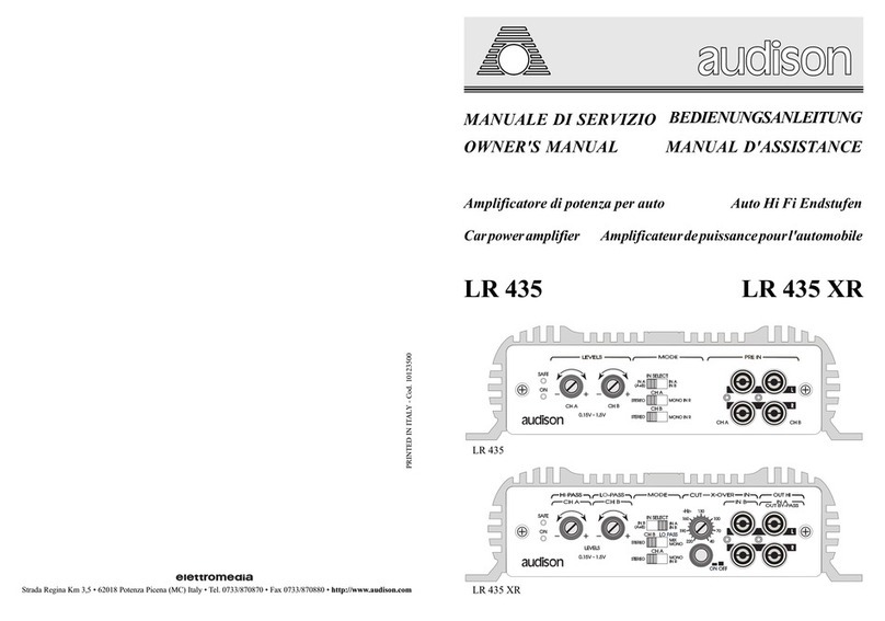
TECH ICAL DATA
POWER SUPPLY 11 ÷ 15 VDC
IDLING CURREN 2 A
MAX CONSUMP ION (Nominal Pwr) 40 A
CON . NOMINAL POWER ( ol. +10%; -5%)
2 ch x 4 Ohms; 0.3% HD; 12 VDC 140 W (RMS)
CON INOUS POWER (2 ch x 4 Ohms; 13.8 VDC) 145 W (RMS)
CON INOUS POWER (2 ch x 2 Ohms; 13.8 VDC) 250 W (RMS)
CON INOUS POWER (4 Ohms; 13.8 VDC)Bridge 500 W (RMS)
RI-MODE CONNEC ION (4 Ohms) 145+145+500 W (RMS-pulse)
DIS OR ION HD (1 KHz; 90% Nominal Pwr) 0.04 %
BANDWID H (-3 dB; Nominal Pwr) 4 Hz ÷ 100 KHz
DAMPING FAC OR (4 Ohms) 60
RISE IME 4 µS
SIGNAL / NOISE RA IO 102 dBA
UNBALANCED INPU SENSI IVI Y 0.3 V ÷ 4 VRMS
BALANCED INPU SENSI IVI Y ±0.15 V ÷ ±2 VRMS
INPU IMPEDANCE 15 KOhms
LOAD IMPEDANCE Stereo 8; 4; 2 Ohms
LOAD IMPEDANCE Mono 8; 4 Ohms
REMO E IN 3 ÷ 15 VDC
REMO E OU 12 VDC - 250 mA
MU E IN 3 ÷ 15 VDC / GND
MU E OU 12 VDC - 5 mA
INPU GROUND (Selectable for balanced input) ON - OFF
DIMENSIONS (WxHxD) 256 x 61 x 370 mm (10.07 x 2.40 x 14.56)
SERVICE CONNECTIONS UNIT FIXING
CONNECTIONS AND FUNCTIONS
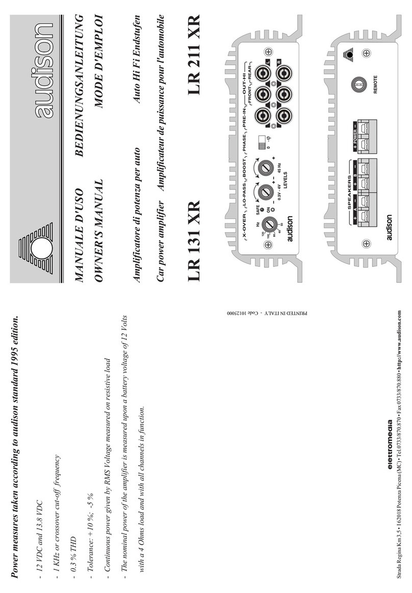
Rear Side
MUTE
I
Mute control coming from radio-cassette player (or any
source provided with output for the amplifier mute).
It is especially made to be connected to the mute output
of a cellular telephone in order to silence the amplifier
for incoming calls, and it allows to reactivate musical
reproduction at the end of phone conversation.
It can be connected to the MU E OU output of a
preceding amplifier to allow the simultaneous silencing
of all amplifiers connected in cascade.
Applied voltage must be between 3 and 15 VDC or
connect to GND.
OUT
Output for the other amplifiers in the sound system.
It must be connected to the MU E IN of the successive
amplifier to allow the simultaneous silencing of all
amplifiers connected in cascade.
he available voltage on this output is 12 VDC with
current equal to 5 mA.
POWER
Input clamps for the
amplifier power
supply.
Connect the battery
positive and negati-
ve according to
indicated polarities.
Applied voltage
mest be between 11
and 15 VDC.
POWER SUPPLY
CLAMPS
REMOTE
I
urn on control for the
amplifier, coming from
radio-cassette player (or
from any sources
provided with remote
control for amplifiers).
Applied voltage must be
between 3 and 15 VDC.
OUT
Output leading to other amplifiers of
the sound system. It has to be connected
to the REMO E IN of the successive
amplifier to allow the simultaneous
turning on of the whole system. he
available voltage on this output is 12
VDC with a current equal to 250 mA.
MUTE AND REMOTE MASTER S AVE CONNECTION
