SPL Elector User manual

2
Welcome
and thank you for choosing the Elector.
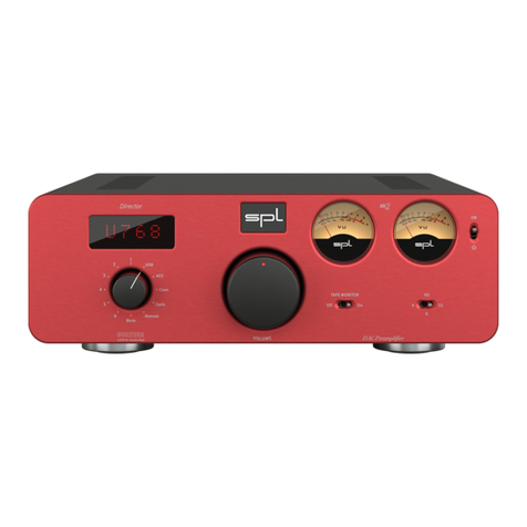
The Elector is based on the Director Mk and designed as a pure analog preamplifier. It features a total of six ana-
log inputs. Three of which are balanced with XLR connectors. The Elector is equipped with the big remote control-
lable aluminum volume control with marker LED and two mechanical VU meters.
Fans of analog tape machines or external audio processing can insert their beloved gear in the Tape Monitor loop.
VOLTAiR technology is what we also call the SPL V Rail Technology within the Professional Fidelity series. This
makes the Elector an outstandig device in terms of dynamic range, signal-to-noise ratio and headroom delivering an
exceptional sound experience with invincible serenity, transparency and realness.
Elector
V
O
L
U
M
E
VOLTAiR
120V DC Au dio Rail Analog Preamplifier
ON
Off On
TAPE MONITOR
6
0
12
VU
2
3
INPUT SELECTOR
4
5
6
1
SEND
–10dB
RETURN
+10dB
Fuses:
230V AC:
T 500 mA L 250 V
115V AC:
T 1 A L 250 V
Voltage Selection:
1. Remove Fuse Holder
2. Exchange Fuses
3. Flip Over
4. Reinstall L LR
Elector
Made in Germany
Refer to
Manual
RISK OF E LECTRI C SHOCK
DO NOT OPEN
CAUTION
RISQUE DE CHOC ÉLECTRIQUE
NE PAS OUVRIR
ATTENTION
R
L
R
L
R
L
R
L
~ 115V AC / ~230V AC, 50Hz / 60Hz, P max. 45 W
456
3LR 2
LR Tape
Monitor
LR 1
B
A
I
R
F

Content
Getting started
Front view
Rear view
VOLTAiR – V Rail Technology
Comparisons
Operation
Source Selection
Volume
Tape Monitor
VU Meter
Attenuate the sensitivity of the VU meters
IR Remote Control
The volume potentiometer can be remotely controlled using
any infrared (IR) remote control
AMP CTL (Amplifier Control)
Specifications
Inputs and Outputs
Analog inputs
Outputs
Measurements
Internal Voltages
Power supply
Dimensions (incl. feet)
Weight
Important Notes
Declaration of CE Conformity
I
R
F

4
Getting started
Getting started
Read thoroughly and follow the instructions as well as the security advices of the Quickstart
which is enclosed in the scope of delivery! You can also download the Quickstart here.
By pressing the -Button you get to the table of contents.
By pressing the -Button you get to the front view of the unit.
By pressing the -Button you get to the rear view of the unit.
By pressing the -Button you get to the previous content.
I
R
F
I
F
R

5
Elector
V
O
L
U
M
E
VOLTAiR
120V DC Audio Rail Analog Preamplifier
ON
Off On
TAPE MONITOR
6
0
12
VU
2
3
INPUT SELECTOR
4
5
6
1
Front view
Front view
Stand-by
1
Power-LED
3
I
R
F
Volume 5
Source 4
VU Meter
2
VU Meter Switch
7
Tape Monitor Switch
6

6
SEND
–10dB
RETURN
+10dB
Fuses:
230V AC:
T 500 mA L 250 V
115V AC:
T 1 A L 250 V
Voltage Selection:
1. Remove Fuse Holder
2. Exchange Fuses
3. Flip Over
4. Reinstall L LR
Elector
Made in Germany
Refer to
Manual
RISK OF ELECTRIC SHOCK
DO NOT OPEN
CAUTION
RISQUE DE CHOC ÉLECTRIQUE
NE PAS OUVRIR
ATTENTION
R
L
R
L
R
L
R
L
~ 115V AC / ~230VAC, 50Hz / 60 Hz, P max. 45 W
456
3LR 2
LR Tape
Monitor
LR 1
B
A
Rear view
Rear view
Mains Switch 11
Mains Voltage 10
I
R
F
Learn IR-Remote-Button 12
Preamp Output 13
AMP CTL
9
Analog Audio Inputs
8
Analog Audio Inputs
8
Tape Monitor
15
Direct Output
14

7
VOLTAiR – 120V Rail Technology
VOLTAiR – V Rail Technology
VOLTAiR is the synonym for our V Rail Technology within the Professional Fidelity series. The audio signals are
processed with an unequalled +/-V DC, which corresponds to twice that of discrete operational amplifiers and
four-times that of semiconductor operational amplifiers.
VOLTAiR Technology reaches outstanding technical and sonic performances. Technically especially in terms of
dynamic range and headroom and sonically especially in reproducing the finest details and delivering a totally
relaxed sounding audio experience. Music sounds absolutely natural.
SPL’s V Rail Technology is the internal audio processing voltage (+/- V DC).
It is not to be confused with the external mains voltage (e.g. V or V AC).
I
R
F

8
VOLTAiR – 120V Rail Technology
Comparisons
These diagrams show how our VOLTAiR Technology compares to other circuits.
The direct relation between operating level and maximum level is fundamental for the classification: the higher
the operating level, the higher the maximum level a circuit can handle. And since virtually all essential acoustic
and musical parameters depend on this relation, a higher operating voltage also has a positive impact on the
dynamic range, distortion limit and signal-to-noise ratio.
0
20
40
60
80
100
120
Volt
30 V
120 V
+ / - Volt + / - Volt
Operating Voltage
120
125
130
135
140
145
dB
124,2
141,4
OPA @ V SPL- OP@ V
Dynamic Range
I
R
F

9
VOLTAiR – 120V Rail Technology
Do bear in mind that dB scales do not represent linear but rather exponential increases. A dB increase corresponds
to doubling the acoustic power, +dB correspond to twice the sound pressure level, and +dB correspond to twice
the perceived loudness.
When it comes to volume, the VOLTAiR Technology exhibits a performance, in regard to maximum level and dynamic
range, that is twice that of common components and circuits given that its values are approximately dB higher.
THD measurements show a difference of more than dB compared to the TL at V — in terms of sound pres-
sure level, that corresponds to an improvement of more than %. The operating level most commonly used for
audio equipment is +/- volts.
Max. Audio Level
OPA @ V SPL- OP@ V
0
5
10
15
20
25
30
35
dBu
21,5
33,2
TL @ V SPL- OP@ V
-115
-113
-111
-109
-107
-105
dBu
-106
-114,2
THD&N
I
R
F

10
Operation
Operation
Source Selection
With the SOURCE switch () you select the source.
Select one of the six analog inputs - .
Volume
You control the volume of the PREAMP OUTPUT () with the VOLUME potentiometer ().
The DIRECT OUT () level is fixed to dBfs and can be used to connect a headphone ampli-
fier.
The VOLUME potentiometer is motorized and can be remotely controlled (seepage).
20
0
%
–+
30 50 70 100
10 75 3 103
5
VU
20
0
%
–+
30 50 70 100
10 75 3 103
5
VU
Elector
V
O
L
U
M
E
VOLTAiR
120V DC Audio Rail Analog Preamplifier
ON
Off On
TAPE MONITOR
6
0
12
VU
2
3
INPUT SELECTOR
4
5
6
1
20
0
%
–+
30 50 70 100
10 75 3 103
5
VU
20
0
%
–+
30 50 70 100
10 75 3 103
5
VU
Elector
V
O
L
U
M
E
VOLTAiR
120V DC Audio Rail Analog Preamplifier
ON
Off On
TAPE MONITOR
6
0
12
VU
2
3
INPUT SELECTOR
4
5
6
1
I
R
F

11
Operation
Tape Monitor
You can insert tape machines or external audio processing devices like an equalizer or Vitalizer
in the Tape Monitor loop.
Insert a tape machine and listen back (tape monitoring) while recording from a vinyl record or
insert beloved equalizers or other processing devices to tune sound.
Connect the SEND () output of the Elector to the input of your external device.
Connect the RETURN () input of the Elector to the output of your external device.
If the send level from the Elector is too high for your external device engage the level
calibration switch beside the tape send and tape return sockets to lower the send
level by dB. The return level will be increased by dB to eliminate a level differ-
ence.
If no external device is connected set the TAPE MONITOR switch to Off.
Otherwise the audio signal is interrupted.
20
0
%
–+
30 50 70 100
10 75 3 103
5
VU
20
0
%
–+
30 50 70 100
10 75 3 103
5
VU
Elector
V
O
L
U
M
E
VOLTAiR
120V DC Audio Rail Analog Preamplifier
ON
Off On
TAPE MONITOR
6
0
12
VU
2
3
INPUT SELECTOR
4
5
6
1
~ 115V AC / ~230V AC, 50Hz / 60Hz, P max. 45 W
SEND
–10dB
RETURN
+10dB
L LR
Refer to
Manual
R
L
R
L
R
L
R
L
456
3LR 2
LR
Tape
Monitor
LR 1
B
A
I
R
F

12
Operation
VU Meter
The VU meters () display the input levels for the selected source. The meter
indicates levels from - dB to + dB.
dB corresponds to + dBu.
The ballistics of the VU meters guarantee an optimal visual perception. The time calibration of the VU meters com-
plies with the requirements of the BBC. The rise time up to dB is about ms.
Attenuate the sensitivity of the VU meters
With the VU switch () you can lower the sensitivity by or dB so that the meters go up to
+ dB intput level if the switch is set to “+”.
20
0
%
–+
30 50 70 100
10 75 3 103
5
VU
20
0
%
–+
30 50 70 100
10 75 3 103
5
VU
Elector
V
O
L
U
M
E
VOLTAiR
120V DC Audio Rail Analog Preamplifier
ON
Off On
TAPE MONITOR
6
0
12
VU
2
3
INPUT SELECTOR
4
5
6
1
20
0
%
–+
30 50 70 100
10 75 3 103
5
VU
20
0
%
–+
30 50 70 100
10 75 3 103
5
VU
Elector
V
O
L
U
M
E
VOLTAiR
120V DC Audio Rail Analog Preamplifier
ON
Off On
TAPE MONITOR
6
0
12
VU
2
3
INPUT SELECTOR
4
5
6
1
I
R
F

13
Operation
IR Remote Control
The volume potentiometer can be remotely controlled using any infrared (IR) remote control
The special feature is that the Elector learns your remote and not the other way around. You do not need a univer-
sal remote control. Take, for example, the remote control of your CD player. Out of the many buttons there are two
you hardly use if at all and that do not directly trigger a function on the CD player.
Programming of the Elector to your remote control is easy and takes just two steps – one for each func-
tion: to the lower volume and increase the volume.
• Press the LEARN IR-REMOTE button () on the rear of the unit until you note the actuation point
The Power LED now lights up brighter.
• Step 1/2: Point your remote control towards the VU meters () and push the button you wish to use to to
lower the volume. The power LED flashes once per push. Press the same button repeatedly until the power
LED flashes three times within a short interval – programming of this button is then completed.
• Step 2/2: Push the button you wish to use to increase the volume. The power LED flashes once per push.
Press the same button repeatedly until the power LED flashes three times within a short interval –
programming of this button is then completed.
~ 115V AC / ~230V AC, 50Hz / 60Hz, P max. 45 W
SEND
–10dB
RETURN
+10dB
L LR
Refer to
Manual
R
L
R
L
R
L
R
L
456
3LR 2
LR Tape
Monitor
LR 1
B
A
I
R
F

14
Operation
Learn mode ends automatically after the second button is learned.
Please note: direct insolation of strong light (e.g. sun light, halogen lamps, neon tubes, fluorescent tubes, terrar-
ium and aquarium lights as well as big flat screens) may lead to misoperation of the remote control functions.
I
R
F

15
AMP CTL (Amplier Control)
If you own SPL Performer power amplifiers or other amplifiers using V trigger inputs you can
connect the AMPCTL () outputs of the Elector with mono mini jack cables to the AMP CTL of the
ampsto trigger on and standby.
Up to two amplifiers can be triggered together.
~ 115V AC / ~230VAC, 50Hz / 60Hz, P max. 45 W
SEND
–10dB
RETURN
+10dB
L LR
Refer to
Manual
R
L
R
L
R
L
R
L
456
3LR 2
LR Tape
Monitor
LR 1
B
A
I
R
F

16
Specications
Specications
Inputs and Outputs
Analog inputs
• analog stereo inputs
• x XLR, balanced ( kOhm)
• x RCA, unbalanced ( kOhm)
• Max. input level: +, dBu
Outputs
• analog stereo outputs
• Neutrik XLR, balanced, Pin = (+)
• RCA, unbalanced (Direct Out)
• Impedance: ohms (balanced)
• max. output level , dBu
I
R
F

17
Specications
Measurements
• Frequency range: Hz (-. dB), kHz (-. dB)
• Crosstalk at kHz: - dB
• THD: . % ( dBu)
• Noise (A-weighted): -. dB
• Dynamic range: dB
Internal Voltages
• Analog: +/- V
Power supply
• Mains voltage (switchable): V AC / Hz or V AC / Hz
• Fuses: V: T mA; V: T A
• Power consumption: max. VA
• Standby power consumption: . W
I
R
F

18
Specications
Dimensions (incl. feet)
• mm W x mm H x mm D
• . in W x . in H x . in D
Weight
• . kg; . lbs (unit only)
• . kg; . lbs (shipping)
I
R
F

19
Important Notes
Important Notes
Version . – /
Developer: Bastian Neu
This manual includes a description of the product but no guarantee as for specific characteristics or successful
results. Unless stated otherwise, everything herein corresponds to the technical status at the time of delivery of
the product by SPL electronics GmbH. The design and circuitry are under continuous development and improve-
ment. Technical specifications are subject to change.
© SPL electronics GmbH. This document is the property of SPL and may not be copied or reproduced in any
manner, in part or fully, without prior authorization by SPL. Sound Performance Lab (SPL) continuously strives to
improve its products and reserves the right to modify the product described in this manual at any time without
prior notice. SPL and the SPL Logo are registered trademarks of SPL electronics GmbH. All company names and
product names in this manual are the trademarks or registered trademarks of their respective companies.
Declaration of CE Conformity
The construction of this unit is in compliance with the standards and regulations of the European Com-
munity.
I
R
F
Table of contents
Other SPL Amplifier manuals

SPL
SPL Reducer 1160 User manual

SPL
SPL Professional Fidelity Elector User manual

SPL
SPL performer s800 User manual

SPL
SPL HPM User manual

SPL
SPL 1320 User manual

SPL
SPL 2485 User manual

SPL
SPL Track One 2960 User manual

SPL
SPL performer s800 User manual

SPL
SPL Phonitor xe User manual

SPL
SPL Director User manual

SPL
SPL Channel One Mk3 User manual

SPL
SPL Phonitor 2 User manual

SPL
SPL Phonitor se User manual

SPL
SPL 2047 User manual

SPL
SPL Perfomer s800 User manual

SPL
SPL Phonitor 2 1280 User manual
SPL
SPL GainStation 8 Mk2 User manual

SPL
SPL Channel One Mk3 User manual

SPL
SPL Phonos User manual

SPL
SPL Performer m1000 User manual