KAT TB PLUSH KIT User manual
KAT-KIT TB PLUSH KIT
Welcome to the KAT-KIT TB PLUSH Build-It-Yourself-Kit.
Firstly, a little info on the TB. For starters, the components provided are the best for the job in-hand.
They are the same components used for the builds of many KAT TB’s and Fryer Sound TB Touring,
Deluxe and Plus Treble Boosters. The circuit board has been specially designed for the kit so that the
build can be easy with all components identified on the board. The case is the same powder-coated,
silk-screened folded steel unit used for the TB Touring, Deluxe and Plus, so rugged, durable and yet,
attractive.
Sound-wise, this TB has been developed to emulate the 1980’s era of Brian May’s tone, so think
Queen from the late 70’s through to the end. Think Wembley… Think Live Aid!!
So, what’s in the kit?
Well, everything you need to successfully build the TB except for a few hand tools and a battery.
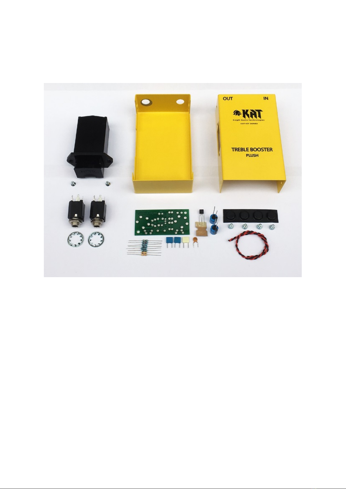
Here are the only tools you will need to
build this kit:
1. Soldering Iron (25 – 40W)
2. Multicore solder
3. Cutters
4. No. 1 Pozidriv screwdriver
5. Large pair of pliers
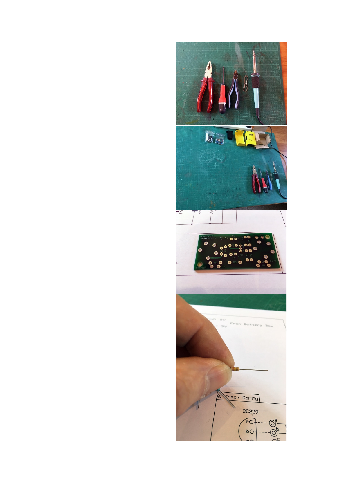
We would suggest that you set up on a
large piece of cardboard or cutting board
along these lines.
So, Let’s start with the circuit board. It is
double-sided with plated tracks and solder
resist to stop solder going where it’s not
wanted. The top of the board has
component idents and orientation marks
to assist the build.
Always start a build with the smallest parts
first, which, in this case is the resistors.
There is a resistor colour-code chart at the
end of this set of instructions to help you
identify each one, so let’s start with R1.
This is a 120Kohm resistor (4 band colours,
so Brown/Red/Yellow – Gold).
The first thing we need to do is pre-form
(bend) the legs ready to insert the device in
the board. To do this, hold the resistor in
your hand with your thumb nail resting on
the end of the resistor body:
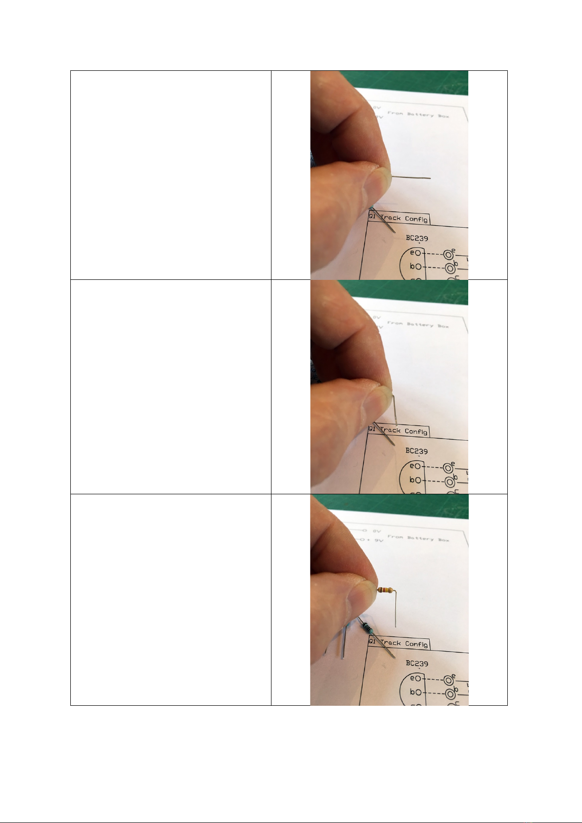
With your finger, bend the leg towards you
at 90 degrees so that the lead is formed
around your thumb nail.
So, it looks like this. Then do the same to
the other leg so both are now bent in the
same direction:

Your formed legs now looking like this and
ready to be dropped into the board.
Find the location of ‘R1’ on the board and
drop the resistor into the holes from
above. It is good practice (but not
necessary) to orientate the resistors so
that the colour codes either read from left
to right, or from bottom to top. This just
makes repairs and fault-finding further
down the line a little easier…
With the resistor dropped in, make sure it
is seated all the way down and touching
the top of the board at both ends. Now
gently bend the legs open underneath so
as to temporarily hold the component in-
place whist you load the rest.

You should now have a board populated
with 8 resistors. There is a ‘check picture’
further along in these instructions if you
want to check you have the correct
components in the correct place before
you solder. If you are colour-blind in any
way, or have sight impairment, you can
check values with a multi-meter touched
across the ends of each resistor in turn.
Now carefully turn the board over so that
all the resistors are flat against the work
surface. If you apply gentle pressure to the
board as you solder, you will find that all
the components are perfectly seated once
soldered.
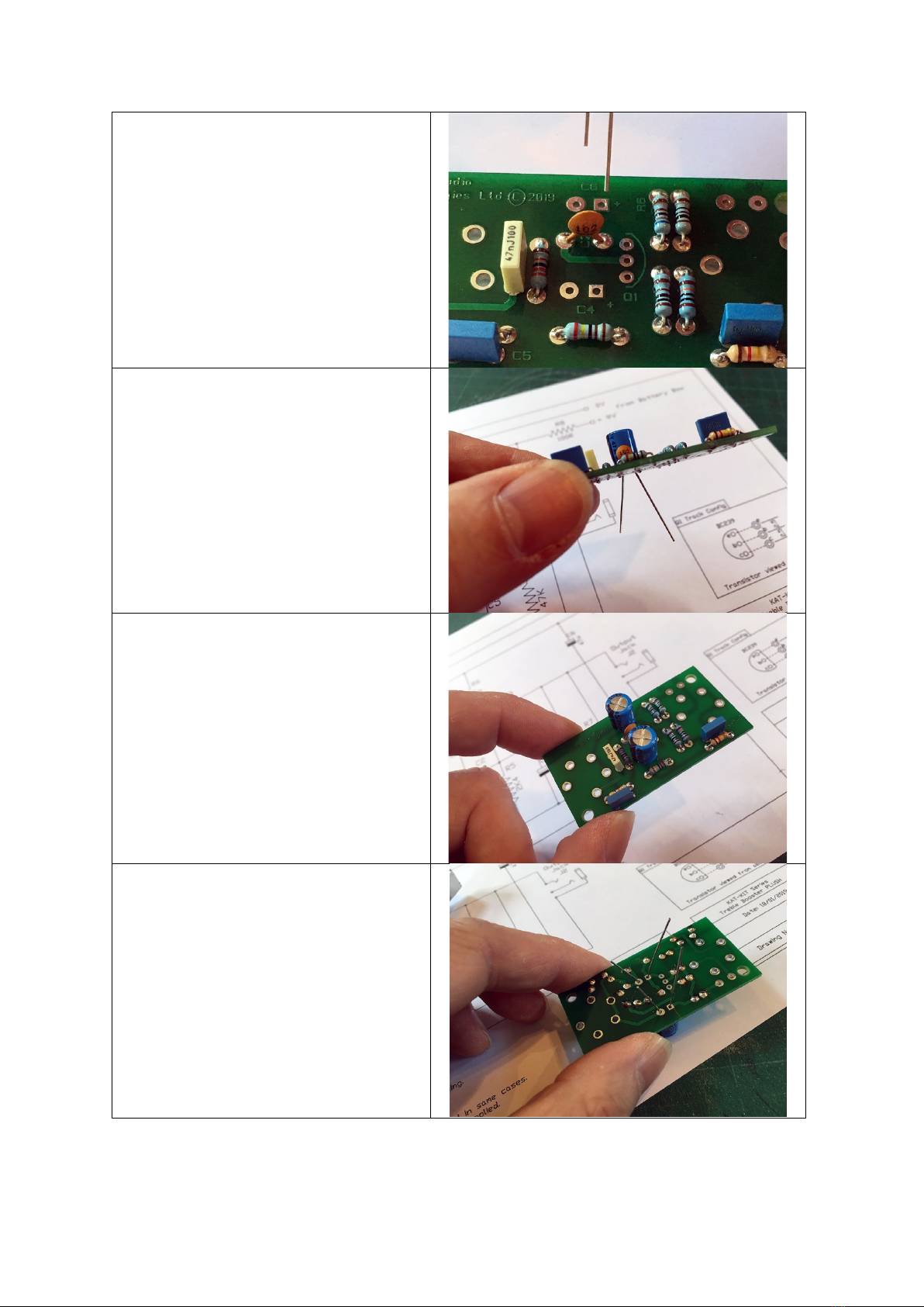
So, here’s the board with the resistors just
soldered in and ready for the leads to be
trimmed. Each solder joint should have a
concave shape (slightly sunken), rather
than convex (pudding shaped). If your
joints are convex, you are applying too
much solder. Your solder-time per joint
should not exceed 3 seconds. If in doubt,
count 1 (apply soldering iron to joint), 2
(feed in solder), 3 (remove iron).
Once you have soldered the leads and
checked the solder joints for quality, you
can then trim off the leads with your
cutters. Bad solder joints will have a dull
grey look to them, good joints will be
shiny. Make sure there are no gaps in the
solder around the lead at the pad. The
solder pad hole should be full with solder.

Now it’s time to move on to the small
polyester and ceramic capacitors. The
value of which is either written on the
front or the top of each device. Again,
further help can be found at the back of
this piece.
As per the resistors, you can drop the four
capacitors into their respective holes as
detailed.
Once again, bending the legs below the
board to temporarily hold them in place
before soldering:
The small capacitors are now in and ready
for soldering. Time to flip the board and
rest it on the top of the new capacitors.

Board inverted ready for soldering.
Small capacitors now soldered in, you can
cut the excess leads off with your cutters.
Your board should now look like this!..
Now for the larger Electrolytic capacitors.
There are two in this circuit and both are
the same value, so you don’t need to worry
about fitting the wrong one. There are two
types of Electrolytic capacitor used in these
kits: the blue one (shown) and a silver one.
Electrolytic capacitors are polarised and
have to be inserted the correct way
around. They have a plus leg and a minus
leg. The plus leg is the longest and the
minus leg the shortest. The minus side of
the cap also has a black (-) band down the
side.
The board also has polarising orientation
marks within the idents. The square solder
pad is the plus and the round, the minus.
On these boards, the plus side also has a
(+) symbol next to it. So, as per the pic to
the right, the long leg goes in the square
hole!..
Again, as before, bend the leads outwards
to hold the component in place.
Both Capacitors now in place. Check
polarity one more time before you turn the
board over to solder.
Capacitors ready to be soldered.
Capacitors and resistors now installed.
Your board should look like this!…
Transistor-Time!...
The transistor is the ‘engine-room’ of the
Treble Booster. They are all different, have
different responses and gains and can be
right diva’s if not handled with care. Firstly,
they HAVE to be oriented the correct way
around FIRST TIME, otherwise they will self
-destruct on power-up! Some can be a
little sensitive to static, so try not to handle
the leads too much (especially if you’ve
been walking across a nylon carpet)!!.
They are also heat sensitive, so we have to
be careful when soldering them in!
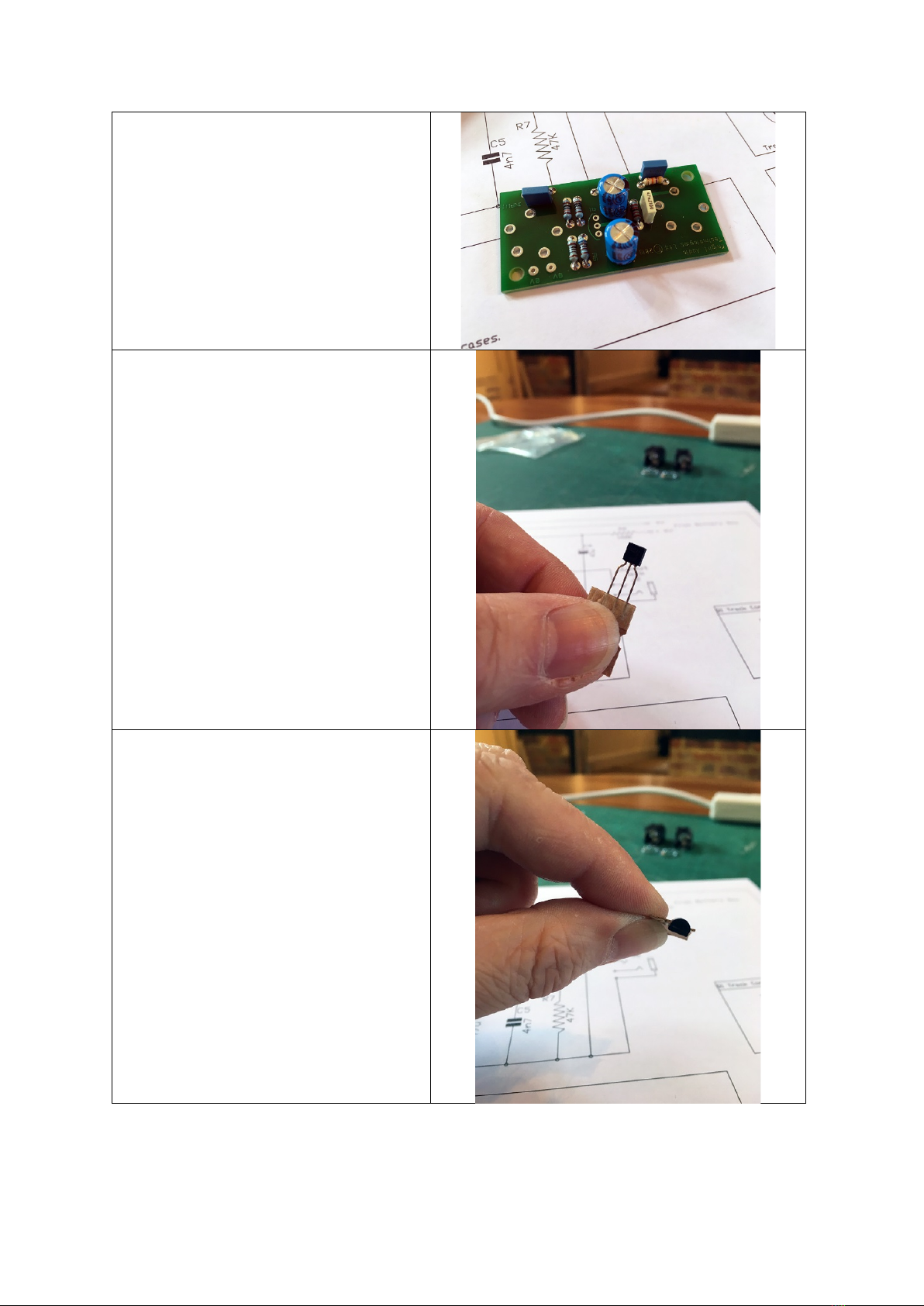
But first, let’s get your transistor in to the
board the correct way around. If you look
at the transistor, you’ll note that it has a
round body with a flat on one side.

If you now look at the board, you’ll notice
that we have put a curved ident on the
board to one side of the holes. This curved
ident signifies the round side of the
transistor.
Here is the board with the transistor
dropped in.
In order to set the correct length of the
transistor leads, turn the board over and
rest it on the tops of the large Electrolytic
capacitors. Then lower the transistor back
through the holes so that its body also
rests on the worksurface. In other words,
the top of the transistor is set to the same
height as the tops of the large capacitors.
The transistor leads are now straight and
ready for soldering. My general rule is this:
Solder the middle lead first. Let it cool for
10 seconds. Then solder the left-hand lead.
Let that cool for ten seconds. Then solder
the final lead.
This process stops heat build-up in the core
(junction) of the transistor. If you stick to
the 3 second rule detailed earlier and set
the height as mentioned, you shouldn’t
need any heatsinks on the leads.
Other KAT Amplifier manuals


