KBR MWV User manual

22062_EDEBDA0236-1218-1_EN
User manual
Technical parameters
Your partner for
network analysis
Measuring
transducer adapter MWV
System IEnglish

© KBR Kompensationsanlagenbau GmbH
Misprints, printing errors
and technical changes reserved
2
KBR MWV measuring transducer adapter

Rev. 1.00 3
22062_EDEBDA0236-1218-1_EN
KBR MWV measuring transducer adapterTable of contents
Table of contents ................................................3
Disclaimer .............................................................5
Safety notes..........................................................6
Product liability...................................................7
Disposal..................................................................7
Scope of delivery................................................7
1 Application............................................8
1.1 The following transducer types
are available: .........................................8
2 Installing the device...........................8
3 Connection diagram..........................9
4 Dimensions......................................... 10
5 Technical data.................................... 11
Table of contents

Rev. 1.00
22062_EDEBDA0236-1218-1_EN
4
KBR MWV measuring transducer adapter Introduction
Dear customer
Thank you for choosing a KBR product.
To familiarize yourself with the operation and conguration of the device, we recommend
that you read this manual carefully. This way, you will be able to use of the entire range of
functions that this high-quality product has to oer.
The individual chapters explain the technical details of the device and show how to prop-
erly install and start it up to prevent damage.
This user manual is included in the scope of delivery of the device and must be accessible
to the user at all times (e.g. in the switchgear cabinet). Even if the device is resold to third
parties, the manual remains an inherent part of the device.
Although the utmost care has been taken in putting together this user manual, errors
may still occur. We would be very grateful if you could notify us of any errors or unclear
descriptions you may notice. The form included in the appendix to this manual can be
used to send us corrections or suggested improvements.
Yours sincerely,
KBR GmbH Schwabach

Rev. 1.00
22062_EDEBDA0236-1218-1_EN
5
KBR MWV measuring transducer adapterIntroduction
This manual contains notes that must be observed for your personal safety and
to prevent damage to the equipment. These notes are identied by a warn-
ing sign or information symbol, depending on the degree of hazard they warn
about.
DANGEROUS VOLTAGE
means that death, major injury or substantial property damage may occur if the
appropriate safety measures are not taken.
CAUTION
means that minor injuries or property damage may occur if the appropriate
safety precautions are not taken.
NOTE
is an important piece of information on the product, product handling or the
respective part of the user manual to which special reference is made.
Disclaimer
The contents of this manual have been checked to concur with the described
hardware and software components. However, deviations may occur, meaning
that no guarantee can be made for complete agreement with the documenta-
tion. The specications given in this manual are checked on a regular basis;
necessary corrections will be included in the next revision.
We appreciate your corrections and comments.

Rev. 1.00
22062_EDEBDA0236-1218-1_EN
6
KBR MWV measuring transducer adapter Introduction
Safety notes
In order to prevent operating errors, handling of the device has been kept as
simple as possible. This will enable you to use the device very quickly. Be sure to
carefully read the following safety notes.
DANGEROUS VOLTAGE
The applicable DIN/VDE regulations must be observed for installation!
Power supply connection, setup and operation of the device may only be
performed by qualied personnel. Qualied personnel as dened in the safety
notes in this user manual are personnel with electrical engineering qualica-
tions, knowledge of the national accident prevention regulations and safety
engineering standards as well as of the installation, commissioning and opera-
tion of the device.
To prevent re and electric shock, do not expose the device to rain or moisture!
Before connecting the device to the power supply, check whether the local
power supply conditions comply with the specications on the device name-
plate.
A faulty connection may result in the destruction of the device!
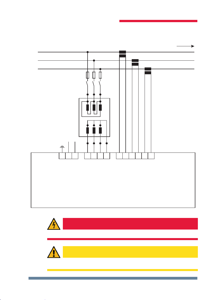
When connecting the device, ensure that the data given in the connection
chart is complied with (see "Connection diagram") and that the connection
cables are not live. When wiring, always ensure that all wiring material used is
neither damaged nor defective
and that the polarity is correct!
For proper and safe product operation, ensure that the device is transported,
stored, installed, assembled, and carefully operated and maintained in accor-
dance with the specications.
A visibly damaged device must generally be considered unt for use and dis-
connected from the power supply. Troubleshooting, repairs and maintenance
work may only be carried out in our facilities or after contacting our service
team.
Opening the device without authorization will render your warranty null and
void. Correct operation can no longer be guaranteed!
All input and output cables of systems that are at risk from lightning strikes must
be tted with lightning protection (see chapter "Protective measures" for recom-
mendations).

Rev. 1.00
22062_EDEBDA0236-1218-1_EN
7
KBR MWV measuring transducer adapterIntroduction
Product liability
You have purchased a high-quality product.
Only components of the highest quality and maximum reliability are used.
Each device is subject to long-term testing before it is delivered.
For details on product liability, please refer to our general terms and conditions
for electronic equipment.
The warranty on device properties applies only if the device has been operated
in accordance with its intended use!
Disposal
Devices that are faulty, obsolete or no longer used, must be properly disposed
of.
If required, we will dispose of the devices for you.
Scope of delivery
Included in the scope of delivery:
Device KBR MWV measuring transducer adapter
User manual including technical parameters

Rev. 1.00
22062_EDEBDA0236-1218-1_EN
8
KBR MWV measuring transducer adapter
1 Application
With the measuring transducer adapters (zero-point creators), you can create a virtual
low-impedance neutral point for the measuring device in a three-phase network without
neutral conductor.
In the 600 or 700-V version, you can also use it to adapt the measuring voltage to the
measuring devices.
NOTE
Make sure that the measuring devices are congured for operation with a zero
point creator.
1.1 The following transducer types are available:
Type 400/100: Primary: 400 V phase-phase voltage IEC
Secondary: 100 V phase-phase voltage IEC
Type 600/86 Primary: 600 V phase-phase voltage UL (NRTL)
Secondary: 86 V phase-phase voltage UL (NRTL)
Type 700/100 Primary: 700 V phase-phase voltage IEC
Secondary: 100 V phase-phase voltage IEC
2 Installing the device
The housing of the transducer attachment is designed for mounting in the cabinet
to 35 mm standard rail. The module is snapped on the standard rail.

Rev. 1.00
22062_EDEBDA0236-1218-1_EN
9
KBR MWV measuring transducer adapter
3 Connection diagram
L1
L2
L3
PE 1 2 10 11 12 13 20 21 22 23 24 25
L N L1
U1 V1 W1
U2 V2 W2 MP
L2 L3 N k1 l1
l1
k2
k2
l2
l2
k3
k3
l3
l3
Power
Netz
Measuring voltage
Messspannung
Measuring current
Messstrom
Stromussrichtung
current direction
Die Abbildung zeigt im Auszug die Strom- und
Spannungseingänge des Messgerätes.
The diagram shows the current and voltage inputs
of the measuring device.
DANGEROUS VOLTAGE
The voltage inputs and outputs are not safe to touch.
CAUTION
The device is not suitable for direct current.

Rev. 1.00
22062_EDEBDA0236-1218-1_EN
10
KBR MWV measuring transducer adapter
4 Dimensions
CAUTION
Protect the primary voltage with a back-up fuse. Include a disconnector or
circuit-breaker in the electrical installation of the building. The disconnector
must be close to the device and accessible to the user. It must be marked as an
isolating switch for this device. The isolating switch must be UL/IEC approved.

Rev. 1.00
22062_EDEBDA0236-1218-1_EN
11
KBR MWV measuring transducer adapter
5 Technical data
Type 400 / 100 V – IEC
Primary voltage: 400 V Ph-Ph
Secondary voltage: 100 V Ph-Ph or 57.7 V Ph-Mp
Power Max. 1 VA
Housing DIN rail installation
Weight Approx. 650 g
Dimensions Approx. 87 x 72 mm
Voltage input fuse Max. 1 A slow-blow or C2 automatic
Type 600 / 85.7 V – UL (NRTL)
Primary voltage: 600 V Ph-Ph
Secondary voltage: 85.7 V Ph-Ph or 49.5 V Ph-Mp
Power Max. 1 VA
Housing DIN rail installation
Weight Approx. 650 g
Dimensions Approx. 87 x 72 mm
Voltage input fuse Max. 1 A slow-blow or C2 automatic
Type 700 / 100 V – IEC
Primary voltage: 700 V Ph-Ph
Secondary voltage: 100 V Ph-Ph or 57.7 V Ph-Mp
Power Max. 1 VA
Housing DIN rail installation
Weight Approx. 650 g
Dimensions Approx. 87 x 72 mm
Voltage input fuse Max. 1 A slow-blow or C2 automatic

22062_EDEBDA0236-1218-1_EN
Am Kiefernschlag 7
D-91126 Schwabach,
Germany
P +49 (0) 9122 6373- 0
F +49 (0) 9122 6373 - 83
E info@ kbr.de
www.kbr.de
KBR Kompensationsanlagenbau GmbH
Table of contents