KBS CD350-1313 User manual


1

2
CD290-1004, CD350-1003, CD350-1313, FKU 290 G
,
CD351, KSCD 350.1
CD350-311, CD350-1D, CD350

3
CD350-1004, CD350-2D, KS CD 350.2, CD350-2

4
GB
SAFETY INSTRUCTIONS
Carefully read the Instruction manual! If instructions are not followed,
there is a risk of injury, damage of the appliance and loss of the right to
free warranty service. We recommend to keep the Instruction manual the
whole time you have the appliance. When you sell the appliance pass the
Instruction manual to the new owner of the appliance.
WARNING!
–Do not cover the ventilation holes at the top and on the sides of the
appliance.
–Do not use any mechanical means or electrical devices to hasten the thawing
process when cleaning the freezer compartment.
–Do not use electrical appliances inside the food storage compartments of the
appliance, unless they are of the type recommended by the manufacturer.
–If the supply cord is damaged it must be replaced by the manufacturer, manufacturer
service agent or a similarly qualified person, in order to avoid a hazard.
–Disposal of the appliance should be according to national rules.
–Do not damage the appliance refrigeration system. It contains the refrigerant
gas R600a. If the refrigeration system is damaged:
Do not use any open flame.
Avoid sparks ―do not turn on any electrical devices or lighting
fixtures.
Immediately ventilate the room.
•The appliance should be used only for storing foodstuffs.
•This appliance is not designed for the storage of explosive substances such as
aerosol cans with a flammable propellant.
•It is prohibited to store petrol and other flammable liquids near the appliance.
CONNECTION TO THE MAINS
–The appliance must be plugged into an earthed electricity supply socket. The
earthed electrical socket by which the appliance is connected to the mains
should be in an accessible place.
–IF THE APPLIANCE IS PRODUCED WITH THE SPECIAL SUPPLY CORD
IT CAN BE EXCHANGED ONLY BY THE SAME SPECIAL SUPPLY CORD
PROVIDED BY THE MANUFACTURER.

5
–TO AVOID HAZARDS, DAMAGED POWER SUPPLY CORDS SHOULD
ONLY BE REPLACED BY THE MANUFACTURER, A MAINTENANCE
TECHNICIAN OR A PERSON WITH AN EQUIVALENT QUALIFICATION.
–DO NOT USE extension cords or connectors (adapters), or hubs.
–The frequency and power of the electricity supply must conform to the
general data parameters of the appliance as it is shown in the product label.
–When positioning the appliance be careful that the electrical cord isn’t
squeezed in order to avoid its damage. Do not store heavy objects such as
cooling devices, furniture or other devices next the appliance in such a way
that they could squeeze and damage the electrical cord. This can cause a
short circuit and a fire.
–Make sure that the plug of the electrical cord is not squeezed by the back
wall of the appliance or otherwise damaged. A damaged plug can be the
cause of a fire!
–WARNING! DO NOT OPEN THE COVER OF THE LED
ILLUMINATION. In case that LED illumination is used the service
representative must be contacted when the LED light is defected.
•IF THE APPLIANCE IS UNPLUGGED (FOR CLEANING, MOVING TO
ANOTHER PLACE, ETC.), IT MAY BE REPEATEDLY SWITCHED ON AFTER
15 MIN.
•It is forbidden to use a technically damaged appliance.
•The appliance can’t be disposed of by burning.
•Do not place any switched on electrical devices (such as microwave ovens,
hair dryers, irons, electric kettles or other electrical devices) on top of the
appliance because this may cause ignition of plastic parts.
•Do not place any dishes with liquids on top of the appliance and do not keep
flowers in vases or other liquid-filled vessels on the appliance.
•Do not climb on or sit on the appliance, do not lean on or hang on the
appliance doors.
IF THE APPLIANCE IS OUT OF ORDER AND IT IS NOT POSSIBLE TO
REPAIR IT BY MEANS OF GIVEN RECOMMENDATIONS, UNPLUG IT,
OPEN THE DOORS AND CALL THE SERVICE EXPERT. ONLY A SERVICE
REPRESENTATIVE CAN REMEDY ALL TECHNICAL OR CONSTRUCTION
FAULTS
.

6
GENERAL INFORMATION
The appliance is a vertical display cooler with glass doors and with a fan and is designed for
storage of foodstuffs and for chilling of drinks and for a short-term storage of them.
This ppl i nce is intended f or commerci l u se!
THE APPL ANCE S ECOLOG CALLY CLEAN, CONTA N NG NO MATER ALS HARMFUL TO THE
OZONE LAYER: the refrigerant used is R600a, the foaming agent used for the appliance insulation
is cyclopentane C
5
H
10
.
THE MANUFACTURER GUARANTEES REL ABLE OPERAT ON OF THE REFR GERATOR WHEN THE
AMB ENT TEMPERATURE S +16 TO +32 DEGREES CELS US AND THE RELAT VE A R HUM D TY
NOT GREATER THAN 60 PER CENT.
The appliance climate class is 3. nside temperature class – S (from –2 °C to +14 °C)
NOTE. The manufacturer reserves the right to make future changes to technical parameters and
specifications.
Model CD290-1004
FKU 290 G
CD350-1003/1004
KSCD 350.1/KS CD 350.2
CD350-1D/ CD350-2D
CD351, CD350, CD350-2
Refrigerator total gross volume, L 290 350
Refrigerator net volume, L 275 320
Dimensions (H x W x D), cm
145 x 60 x 60
173 x 60 x 60
Shelf area, dm
2
115 115
Average air temperature inside the
refrigerator, °C from 0 to +10
Rated current, A 1,5 1,7
Weight, kg 58 67
Voltage used
220 - 230V/50HZ
Rated input, W 200 230
Data according to requirements of standard EN SO 23953-2:2005
Product temperature ranges, °C from -2 to +14
Door opening area, m² 0,66 0,80
General product exposure area, m² 0,51 0,62 / 0,58
0,33 l 270 329
Loading of the refrigerator
quantity of bottles, pcs.
0,5 l
PET
1
62
197
Maximum loading of one shelf, kg 50 50
At switched on
lighting At switched
off lighting
At switched on
lighting At switched off
lighting
Energy consumption at ambient temperature
+25 °C:
kWh/24 h
kWh/year
2,05
748
2,02
737
2,14
781
2,07
756
Nominal imput of luminaire, W 3

7
For model CD350-1313, CD350-311
The appliance is a refrigerator with glass doors and is designed for storage and chilling of wine.
The appliance may be used in cafes, bars and etc.
THE APPL ANCE S ECOLOG CALLY CLEAN, CONTA N NG NO MATER ALS HARMFUL TO THE
OZONE LAYER: the refrigerant used is R600a, the foaming agent used for the appliance insulation
is cyclopentane C
5
H
10
.
THE MANUFACTURER GUARANTEES REL ABLE OPERAT ON OF THE REFR GERATOR WHEN THE
AMB ENT TEMPERATURE S +16 TO +32 DEGREES CELS US AND THE RELAT VE A R HUM D TY
NOT GREATER THAN 70 PER CENT.
The appliance climate class is N.
NOTE. The manufacturer reserves the right to make future changes to technical parameters and specifications.
STORAGE OF WINE
Temperature in the storage compartment depends on the
ambient temperature, on the position of the thermostat knob.
Thermostat knob position is set according to the table.
Wine temper ture, °C
Model CD350-1313, CD350-311
Refrigerator total gross volume, L 350
Refrigerator net volume, L 330
Dimensions (H x W x D), cm
173 x 60 x 60
Shelf area, dm
2
120
Average air temperature inside the refrigerator, °C from +4 to +14
Rated current, A 1,0
Weight, kg 67
Voltage used
220 - 230V/50HZ
Rated input, W 150
Door opening area, m² 0,80
General product exposure area, m² 0,62
Loading of the refrigerator (quantity of bottles) 0,75 l
105 pcs.
Maximum loading of one shelf, kg 50
At switched off lighting At switched off lighting
Energy consumption at ambient temperature
+
25 °C:
kWh/24 h
kWh/year
0,930
340 0,880
321
Nominal imput of luminaire, W 3
Position of the thermostat
(ambient temperature
+25 ºC)
Zone
designation 1 2 3 4 5
1 zone 12 – 14 12 – 14 12 - 14 10 – 12 8 – 10
2 zone 10 – 12 10 – 12 9 – 11 8 – 10 6 – 8
3 zone 8 – 10 8 – 10 8 – 10 6 – 8 4 – 6
4 zone 8 – 10 8 – 10 6 – 8 4 – 6 4 – 6
5 zone 8 – 10 8 – 10 4 – 6 2 – 4 2 – 4
6 zone 6 – 8 6 – 8 4 – 6 2 – 4 1 – 3

8
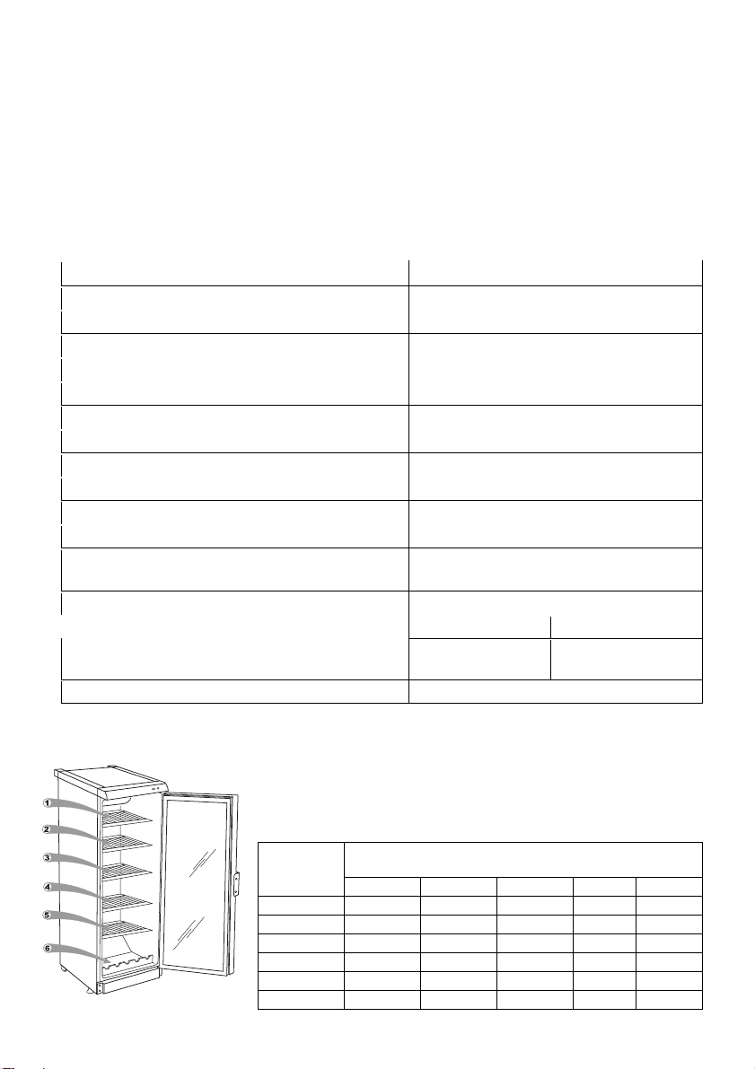
DESCRIPTION OF THE APPLIANCE, BASIC PARTS (see fig. 1)
1 Switch -(ON/OFF); 6 Fan
2 Thermostat knob 7 Shelf
3 Thermostat indicator 8 Cleaner
4 Electricity supply indicator 9 Condenser
5 nterior light block (LED) 10 Compressor
REVIEW OF MECHANICAL CONTROL (see fig. 1)
1 ― On / off switch for interior light. On / off switch for interior light I -(ON) O –(OFF)
2 ― Thermost t knob. The thermostat is off when there is a zero (0) in the thermostat indicator
space. Turning the thermostat knob clockwise the temperature in the compartment lowers.
3 ― Thermost t indic tor. Marked with the symbol
4 ― Electricity supply indic tor, marked with the symbol
When the appliance is connected to the electricity supply, the green indicator light is
illuminated. WARNING! The fan switches on and continuously operates.
PREPARING THE APPLIANCE FOR OPERATION
t is recommended to prepare the appliance for operation with a helper.
•Remove package. Lift the appliance away from foamed polystyrene base.
If your ppli nce is fit with screwed h ndles. Do not rise or push it t king by
h ndles. H ndles m y bre k.
•Therefore take out adhesive tapes from sides and simply lift the appliance up and take out
the board. Strip adhesive tapes off and open the door. Remove the spacer above the door.
•When positioning the appliance in chosen location, it will move more easily into position if you
lift the front a little and incline it backward allowing it to roll on its casters.
•Suitably dispose the packaging material.
•Take two supports from the bag (see fig. 4) and insert them into the guides at the top back
part of the appliance.
POSITIONING
•Place the appliance in a dry, well ventilated room.
WARNING! The appliance should not be operated in an unheated room or
porch. Place the appliance away from heat sources such as kitchen stove/oven,
radiators, or direct sunlight.
WARNING! The appliance must not touch any pipes for heating, gas or
water supply or any other electrical devices.
•Do not cover the ventilation holes at the top of the appliances – it must be a good air circulation
around the appliance. There should be a gap of at least 10 cm between the top of the appliance
body and any furniture that may be above it. f this requirement is not followed, the appliance
consumes more electrical energy and its compressor may overheat.
•f the appliance is placed in a corner, a gap of at least 1 cm must be left between the appliance
body and the wall (see fig. 2).
•The appliance must stand on a level surface and must not touch the wall. f necessary, regulate
the height of the appliance by adjusting the levelling feet: by turning them clockwise – the front
of the appliance rises, by turning them counter clockwise – it comes down. f the appliance is
tilted slightly backward – the doors will close by themselves.

9
TEMPERATURE REGULATION
The temperature in the refrigerator compartment is controlled using the thermostat knob 2 (see
fig. 1) by turning it to one side or the other. The temperature indication in digits is shown beside
the thermostat knob. When the door is closed, the temperature setting can be seen on the
thermostat indicator display 3 (fig. 1). The temperature is regulated on the scale of five digits.
0 = Compressor is switched off. WARNING! Electric current is not switched off.
1 = highest temperature (lowest cooling)
5 = lowest temperature (highest cooling)
f foodstuffs in the refrigerator compartment are too cold, set the thermostat knob to 1, 2 or 3. f
foodstuffs in the refrigerator compartment are not being chilled sufficiently, set the thermostat
knob to 4 or 5.
Please set the desired temperature in the appliance according to your own requirements!
THE TEMPERATURE N THE REFR GERATOR COMPARTMENT MAY VARY DEPEND NG ON
AMB ENT TEMPERATURE, THE AMOUNT OF FOODSTUFFS, THE TEMPERATURE OF THE
FOODSTUFFS, AND HOW OFTEN THE APPL ANCE DOORS ARE OPENED AND CLOSED.
F THE ROOM S COOL, THE APPL ANCE COOLS LESS. THE TEMPERATURE N THE APPL ANCE
MAY THEREFORE R SE. Use the thermostat wheel to set a lower temperature.
CHANGING THE OPENING DIRECTION OF THE DOORS
t is recommended that changing the opening direction of the doors should be done with a helper.
You will need two spanners No. 8 and No. 10 and a Philips head screwdriver.
When changing the opening direction of the doors YOU CAN NOT lay the refrigerator horizontally!
NOTE. Direction of door is not ch nge ble in refriger tors with lock ble doors.
Do the actions below in the order they are listed:
For models CD290-1004, CD350-1003, CD350-1313, FKU 290 G
,
CD351, KSCD 350.1
CD350-311, CD350-1D, CD350 (see fig. 3):
WARNING! Turn off the ppli nce nd pull the plug out of the electricity supply socket.
1. Unscrew two screws 7 and remove the bottom bracket 8 together with the set of washers 6
on the axle and the spacer 5.
2. Unscrew two screws 7 and remove the bracket 11. Remove the door 4.
3. Unscrew the axle 2 together with the nut 1 and washers 3 from the upper bracket and screw
all this set on the reverse side of the door;
4. Before hanging the door, turn the door over by 180
0
and insert the upper axle in the door.
5. Unscrew fixing screws 12 from doors, remove handles 13 and fix them screwing in free holes
on the same side. Plate 10 remains in its place.
6. Before screwing the bottom bracket 8 together with the set of washers and spacers on the
reverse side of a cabinet, insert the bracket axle to the door.
7. Screw the bracket 11 on the reverse side of a cabinet.
For models CD350-1004, CD350-2D, KS CD 350.2, CD350-2 (see fig. 5):
WARNING! Turn off the ppli nce nd pull the plug out of the electricity supply socket.
1. Unscrew two screws 12 and remove the bottom bracket 13 together with the set of washers
11 on the axle and the spacer 10.
2. Unscrew two screws 12 and remove the bracket 15. Remove the bottom door 9.
3. Unscrew fixing screws 7 of the middle bracket. Remove the middle bracket 6 together with
washers on the axle and the spacer 5. Remove the top door 4.
4. Unscrew the axle 2 together with the nut 1 and washers 3 from the upper bracket and screw
all this set on the reverse side of the door.
5. Take out the plugs 18 in the crossbar zone and displace them on the reverse side.
6. Before hanging the upper door, turn the door over by 180
0
and insert the upper axle in the
door.

10
7. Before screwing the middle bracket 6 with the set of washers and spacers on the reverse side
of the cabinet, insert the bracket axle into the upper door;
8. Before hanging the bottom door on the middle bracket axle, turn them over by 180
0
.
9. Unscrew fixing screws 16 from both of door, remove handles 17 and fix them screwing in free
holes on the same side. Plate 14 remains in its place.
10. Before screwing the bottom bracket 13 together with the set of washers and spacers on the
reverse side of a cabinet, insert the bracket axle to the door.
11. Screw the bracket 15 on the reverse side of a cabinet.
DEFROSTING
The refrigerator compartment defrosts automatically. Drops of ice that form on the back wall of the
refrigerator compartment thaw during the time the compressor is not working and the thaw water runs
down the thaw water runoff channel to the tray on top of the compressor, where it evaporates.
CLEANING AND CARE
REGULARLY CLEAN THE APPL ANCE.
Remember th t before cle ning you must disconnect the ppli nce from the
electric l energy supply socket by pulling the plug out of the electricity outlet.
•Protect the appliance inner surfaces and plastic parts from fats, acids and sauces. n case of
accidental spills – immediately clean with warm soapy water or dishwashing detergent. Wipe dry.
•Clean the appliance inner surfaces with warm soapy water. Dishwashing detergent may also be used.
•Wipe dry inner and outer surfaces. Regularly clean the hermetic gaskets of the doors. Wipe dry.
•REGULARLY CLEAN THE THAW WATER CHANNEL SPACE W TH A SPEC AL
CLEANER 8 FOR THAT PURPOSE (Fig. 1).
•At least once a year clean dust away from the back part
of the appliance body and the compressor. A soft brush,
electrostatic cloth or vacuum cleaner may be used for
cleaning.
•DO NOT use detergents containing abrasive particles,
acid, alcohol or benzene for cleaning the appliance inner and outer surfaces.
•DO NOT use for cleaning cloths or sponges that have coarse surfaces intended
for scrubbing.
•F THE APPL ANCE S TO BE LEFT SW TCHED OFF FOR AN EXTENDED PER OD, LEAVE TS
DOORS OPEN.
•ATTENTION! Outer of the doors – glass – clean with agents intended for glass cleaning.
Rem rks on the ppli nce oper tin g noi se. As the appliance operates
and goes through the freezing cycle, various noises will be emitted. This is normal and is
not a sign of any malfunction.
•As the refrigerant circulates around the refrigeration system, it causes sounds like murmuring,
bubbling, or rustling.
•Louder sounds like popping or clicking may be heard for a short time as the refrigerator
compressor switches on.
OPERATION PROBLEMS AND THEIR SOLUTIONS (TROUBLESHOOTING)
Wh t if …
•The ppli nce is plugged in to the m ins but it does not work nd the electricity supply
volt ge indic tor is not illumin ted. Check that your house electricity supply installations are
in order. Check that the plug is correctly inserted into the electricity supply socket.
•The noise h s become louder. Check that the appliance is standing stable, on a level place.
To make it level, regulate the front feet. Check if the appliance is not touching any furniture,
and that no part of the refrigeration system at the back part of the appliance body is touching

11
the wall. Pull the appliance away from any furniture or walls. Check that the cause of increased
noise isn’t due to bottles, cans or dishes in the appliance that might be touching each other.
•W ter h s ppe red t the bottom of the refriger tor comp rtment. Check whether a
thaw water channel space isn’t blocked. Clean the thaw water channel space with a cleaner
intended for that purpose.
•W ter h s ppe red under the ppli nce. The thaw water collection tray has slipped off
the compressor. Place the tray on top of the compressor.
•When the ppli nce door is opened, the rubber se ling g sket pulls out. The gasket is
smeared with sticky foodstuffs (fat, syrup). Clean the sealing gasket and the groove for it with
warm water containing soap or dishwashing detergent and wipe dry. Put the rubber sealing
gasket back into the place.
•High temper ture in ppli nce, the compressor oper tion p uses re short. Ascertain
whether the appliance door/doors are shutting tightly, whether the door wasn’t kept open longer
than necessary when taking out or putting in foodstuffs or whether a large amount of warm
food was placed in the appliance.
•The top of the ppli nce h s condens tion on it. The ambient relative air humidity is
above 60 %. Ventilate the room where the appliance stands and if possible remove the cause
of the humidity.
TRANSPORT
THE MANUFACTURER W LL NOT BE RESPONS BLE FOR ANY DAMAGE OF THE APPL ANCE
THAT RESULTS FROM NON-COMPL ANCE W TH THE NSTRUCT ONS FOR
TRANSPORTAT ON.
•The appliance should be transported only in the vertical position.
•When being transported, the appliance should be protected from atmospheric conditions (rain,
snow, dampness).
•The appliance should be firmly secured in place while being transported, to avoid slippage or any
shocks in the transport vehicle.
•f the appliance was transported not vertically, it may be connected to the mains after 4 hours at
least. f this is not done, the appliance compressor may fail.
ENVIRONMENTAL PROTECTION INFORMATION
This symbol indicates that once the appliance is no longer needed, it cannot be disposed
together with other miscellaneous municipal waste. t should be collected and eliminated
separately, i.e. in containers specially marked with this symbol in large-dimension rubbish
collection areas. Full information on where to submit the old appliance safety can be
obtained from local government authorities, the shop where you bought the appliance or the
manufacturer’s representatives.
f you decided to scrap the appliance, make it impossible to use in order to prevent possible
misadventure. Pull out the electric plug from the electricity supply socket and then cut off the cord.
Tear off the gasket. Break the door lock if any.
WARNING! Do not dism ntle the ppli nce yourself. P ss it on to recycling
comp nies.
WARRANTY SERVICE
F YOUR APPL ANCE S NOT WORK NG PROPERLY,
ASCERTA N WHETHER YOU CAN REMEDY THE CAUSE OF
THE FAULTY FUNCT ON NG OF THE APPL ANCE
YOURSELF. f you cannot solve the problem yourself,
contact the nearest refrigerator service representative by
telephone or in writing. When making contact necessarily
indicate the refrigerator model 1 and number 2. You will
find this data on the product label, which is glued to the wall.

12
DE
SICHERHEITSHINWEISE
LESEN SIE BITTE DIE GEBRAUCHSANWEISUNG SORGFÄLTIG DURCH !
Bei Nichtbeachtung der in der Gebrauchsanweisung genannten
Anweisungen besteht die Gefahr der Beschädigung des Geräts und des
damit verbundenen Verlusts des Rechts auf Garantieleistungen. Wir
empfehlen ihnen, die Gebrauchsanweisung bis zum Ende der Betriebszeit
aufzubewahren und sie im Falle eines Verkaufs des Geräts an den neuen
Eigentümer weiterzugeben.
ACHTUNG!
−Halten Sie die Lüftungsöffnungen im Gerategehäuse oder in möglichen
Seitenwändenvon umgebenden Einbauwänden frei von Hindemissen.
−Benutzen Sie keine mechanichen Gegenstände order andere Mittel, um den
Abtauprozess zu beschleunigen, ausser den vom Hersteller empfohlenen.
−Das Kühlsystem des Geräts nicht beschädigen. Verwendetes Kühlmittel
R600a. Falls das Kühlsystem beschädigt ist:
Kein offenes Feuer verwenden.
Funkenschlag vermeiden, keine elektrischen sowie
Beleuchtungsgeräte einschalten.
Den Raum sofort durchlüften.
•
Das Kühlgerät nur Aufbewahrung von Esswaren verwenden.
•
In diesem Gerät keine explosionsfähigen Stoffe, wie zum Beispiel
Aerosolbehälter mit brennbarem Treibgas, lagern.
NETZANSCHLUSS
−Das Kühlgerät unbedingt an eine geerdete Steckdose anschließen. Die
geerdete Steckdose für den Netzanschluss des Geräts sollte sich an gut
zugänglicher Stelle befinden.
−VOR DEM AUFSTELLEN EIN DEFEKTES KABEL UNBEDINGT DURCH
EIN NEUES VOM SELBEN TYP WIE DAS VOM HERSTELLER DES
KÜHLGERÄTS VERWENDETE ERSETZEN, UM SCHADEN AN
GESUNDHEIT UND EIGENTUM ZU VERMEIDEN.
−UM JEGLICHES RISIKO AUSZUSCHLIESSEN, DARF EIN SCHADHAFTES
NETZKABEL NUR VOM HERSTELLER, DESSEN WARTUNGSMEISTER
ODER EINER ENTSPRECHEND AUSGEBILDETEN PERSON
AUSGEWECHSELT WERDEN.

13
−Das Verwenden von Verlängerungskabeln, Adaptern oder
Mehrfachsteckdosen ist NICHT ZULÄSSIG.
−Netzspannung und -frequenz müssen mit den in Angaben in der Tabelle über
die allgemeinen Eigenschaften des Kühlschranks übereinstimmen.
−Beachten Sie bitte beim Aufstellen des Kühlgeräts, dass dieser das
Netzkabel nicht beschädigt. Nichts Schweres wie Kühlgeräte, Möbel oder
andere geräte auf das Stromkabel stellen, um dieses nicht zu beschädigen.
Andernfalls könnte dies zu einem Kurzschluss und zu einem Brand führen.
−Achten Sie darauf, dass die Rückwand des Kühlgeräts den Netzstecker nicht
berührt oder letzterer in irgendeiner Weise beschädigt ist. Ein defekter
Netzstecker kann zu einem Brand führen!
−ACHTUNG! DIE ABDECKUNG DER LED-BELEUCHTUNG
NICHT ENTFERNEN. Wenn eine LED-Beleuchtung vorhanden ist darf
diese im Falle eines Ausfalls/Defekts nur durch den autorisierten
Kundendienst ausgewechselt/repariert werden.
•
NACH DEM AUSSCHALTEN DES GERÄTS (ZUR REINIGUNG, ZUM
AUFSTELLEN AN EINEM ANDEREN PLATZ USW.) DIESES ERST NACH
MINDESTENS 15 MINUTEN WIEDER ANS NETZ ANSCHLIEßEN.
•
Die Benutzung eines technisch nicht einwandfreien Geräts ist zu unterlassen.
•
Vor der Reinigung das Gerät ausschalten und den Netzstecker aus der
Steckdose ziehen.
•
Das Gerät darf nicht verbrannt werden.
•
Schützen Sie die Innenwände und alle Kunststoffteile des Kühlgeräts vor
Kontakt mit Fett, Säuren und Soßen.
•
Bitte keine elektrischen Geräte wie Mikrowellengeräte, Haartrockner,
Bügeleisen, Wasserkocher und ähnliche auf den Kühlschrank stellen:
Kunststoffteile könnten sich entzünden.
NUR DER SERVICE-FACHMANN IST IMSTANDE, TECHNISCHE
MÄNGEL ZU BEHEBEN
.
TRANSPORT
BE N CHTBEACHTUNG DER TANSPORTVORSCHR FTEN KANN DER HERSTELLER N CHT
FÜR ENTSTEHENDE SCHÄDEN HAFTBAR GEMACHT WERDEN.
Das Kühlgerät nur in vertikaler Lage transportieren.
Während des Transports muss das Kühlgerät vor atmosphärischen Einwirkungen (Regen, Schnee,
Feuchtigkeit) geschützt sein.
Das Kühlgerät muss gut befestigt sein, um Verrutschen und Beulen durch Schläge während des
Transports zu vermeiden.
Falls das Gerät nicht in vertikaler Lage transportiert wurde, darf es erst nach mindestens vier
Stunden ans Netz angeschlossen werden. Bei Nichtbeachtung dieser Vorschrift droht der Ausfall
des Kompressors.

14
ALLGEMEINE DATEN
Der Kühlschrank ist ein Kommerzkühlschrank–Vitrine mit einer Glastür und einem Ventilator, der
für die Abkühlung, Exponierung und Aufbewahrung von Lebensmitteln und Getränken geeignet ist.
Die se Geräte sind für de n gew e rblichen Gebr u c h bestimmt!
DER KÜHLSCHRANK ST UMWELTFREUNDL CH, ER BE NHALTET KE NE D E OZONSCH CHT
SCHÄD GENDEN MATER AL EN: als Kühlmittel wird R 600a verwendet, die solierung hres Geräts
besteht aus Zyklopentan C
5
H
10
.
DER HERSTELLER GARANT ERT E NE ZUVERLÄSS GE FUNKT ON DES KÜHLSCHRANKS BE E NER
UMGEBUNGSTEMPERATUR VON +16 B S +32 GRAD CELS US UND E NER VERHÄLTN SMÄSS GEN
LUFTFEUCHT GKE T VON B S ZU 60 PROZENT.
Der Kühlschrank gehört der Klimaklasse 3 an. Die nnentemperaturklasse ist S (von -2 °C bis +14 °C).
Gerauschemission ‹ 70 dB(A).
ANMERKUNG. Der Hersteller behält sich das Recht vor, die in der Gebrauchsanweisung genannten
technischen Eigenschaften des Geräts sowie dessen Ausstattung zu ändern.
Modell CD290-1004
FKU 290 G
CD350-1003/1004
KSCD 350.1/KS CD 350.2
CD350-1D/CD350-2D
CD351, CD350, CD350-2
Gesamtbruttovolumen, L 290 350
Nutzinhalt Kühlteil, l 275 320
Abmessungen (Höhe/Breite/Tiefe), cm
145x60x60
173x60x60
Aufstellfläche, dm
2
115 115
Temperatur im Kühlteil, °C von 0 bis +10
Strom, A 1,5 1,7
Masse, kg 58 67
Nennspannung
220 - 230V/50HZ
Leistungsaufnahme, W 200 230
Daten gemäß den Anforderungen der Norm EN SO 23953-2:2005
Größe und Temperaturbereiche, °C von -2 bis +14
Fläche zum Türaufmachen, m² 0,66 0,80
Allgemeine Produkt-Exposition Bereich, m²
0,51 0,62 / 0,58
0,33 l 270 329
Anzahl der Flaschen, Stc:
0
,
5 l
PET
1
62
197
Max. Belastung pro Ablage kg 50 50
Bei einges-chalteter
Beleuchtung
Bei ausgeschal-
teter
Beleuchtung
Bei einges-chalteter
Beleuchtung
Bei ausgeschal-
teter
Beleuchtung
Energieverbrauch:
kWh / 24 h
kWh / year
2,05
748
2,02
737
2,14
781 2,07
756
Nennbeleuchtungsleistung, W 3

15
Für die Kühlschränke CD350-1313, CD350-113
Der Kühlschrank ist ein Kommerzkühlschrank–Vitrine mit einer Glastür, der für die Abkühlung,
Exponierung und Aufbewahrung von Lebensmitteln und Getränken geeignet ist.
DER KÜHLSCHRANK ST UMWELTFREUNDL CH, ER BE NHALTET KE NE D E OZONSCH CHT
SCHÄD GENDEN MATER AL EN: als Kühlmittel wird R 600a verwendet, die solierung hres Geräts
besteht aus Zyklopentan C
5
H
10
.
DER HERSTELLER GARANT ERT E NE ZUVERLÄSS GE FUNKT ON DES KÜHLSCHRANKS BE E NER
UMGEBUNGSTEMPERATUR VON +16 B S +32 GRAD CELS US UND E NER VERHÄLTN SMÄSS GEN
LUFTFEUCHT GKE T VON B S ZU 70 PROZENT.
Der Kühlschrank gehört der Klimaklasse N an. Gerauschemission ‹ 70 dB(A).
DIE TEMPERATUR DES WEINES °C
Die Temperatur im Kühlraum hängt von der
Umgebungstemperatur, von der Stellung des
Thermoreglergriffes und von der Menge des aufbewahrten
Weines ab.
Model CD350-1313, CD350-311
Gesamtbruttovolumen, L 350
Nutzinhalt Kühlteil, l 330
Abmessungen (Höhe x Breite x Tiefe), cm
173 x 60 x 60
Aufstellfläche, dm
2
120
Temperatur im Kühlteil, °C from +4 to +14
Strom, A 1,0
Masse, kg 67
Nennspannung
220 - 230V/50HZ
Leistungsaufnahme, W 150
Fläche zum Türaufmachen , m² 0,80
Allgemeine Produkt-Exposition Bereich, m² 0,62
Anzahl der Flaschen, Stc 0,75 l 105 pcs.
Max. Belastung pro Ablage kg 50
Bei eingeschalteter
Beleuchtung
Bei ausgeschalteter
Beleuchtung
Energieverbrauch:
kWh/24 h
kWh/year
0,930
340 0,880
321
Nennbeleuchtungsleistung, W 3
Die Lage der Thermoreglers
(Bei Umgebungstemperatur +25 ºC)
Die Bezeichnung
der Zone 1 2 3 4 5
1 zone 12 – 14 12 – 14 12 - 14 10 – 12 8 – 10
2 zone 10 – 12 10 – 12 9 – 11 8 – 10 6 – 8
3 zone 8 – 10 8 – 10 8 – 10 6 – 8 4 – 6
4 zone 8 – 10 8 – 10 6 – 8 4 – 6 4 – 6
5 zone 8 – 10 8 – 10 4 – 6 2 – 4 2 – 4
6 zone 6 – 8 6 – 8 4 – 6 2 – 4 1 – 3

16
BESCHREIBUNG DES GERÄTS, HAUPTBESTANDTEILE (siehe Abb. 1)
1 Schalter 6 Ventilator
2 Temperaturregler 7 Regal
3 Anzeige der Temperaturregelung 8 Reinigungsinstrument für die
Tauwasserauffangrinne (rot)
4 Stromanzeige (grün) 9 Kondensator
5 Leuchte (LED) 10 Kompressor
STEUERUNG UND LICHTSIGNALISIERUNG (siehe Abb. 1)
1 ― SCHALTER. Die Beleuchtung des Kühlbereiches wird mit dem Drücken des Schalters 1
eingeschaltet. | - ein. O – aus.
2 ― TEMPERATURREGLER. Der Thermoregler in der Stellung "0" (AUS) schaltet aus dem Netz
nur den Kompressor aus. Bei Drehung des Thermoreglergriffs im Uhrzeigersinn sinkt die
Temperatur im Kühlbereich.
3 ― ANZEIGE DER TEMPERATURREGELUNG
4 ― STROMANZEIGE (GRÜN) Die aufleuchtende grüne Signallampe 4 zeigt an, dass der
Kühlschrank ans Netz angeschaltet ist. n Kühlschränken mit Ventilator schaltet sich der
Ventilator mit ein und arbeitet ununterbrochen.
VORBEREITUNG DES GERÄTS
Wir empfehlen, für die Vorbereitungsarbeiten eine weitere Person heranzuziehen.
•Die Verpackung entfernen. Den Kühlschrank von der Schaumstoffunterlage nehmen.
•Klebebänder entfernen.
•Neigen Sie beim Aufstellen den Vorderteil des Kühlschranks ein wenig nach hinten, dann können
Sie ihn auf den Rädchen leicht an den gewünschten Platz rollen.
Ist Ihr Kühlschr nk mit ngeschr ubten H ndgriffen usgest ttet, so beim
Anheben und Verschieben des Kühlschr nks bitte nicht uf H ndgriffe zu
nehmen, um ihren Abbruch zu vermeiden.
•Klebeband entfernen und die Tür öffnen. Den Dichtungssatz über der Tür entfernen.
•Entsorgen Sie die Verpackungen fachgerecht.
•Zwei Abstandshalter (1) aus dem Beutel herausnehmen und in die Halterungen (2) auf der
Rückseite des Gerätes einsetzen (siehe bb. 4).
AUFSTELLUNG
ACHTUNG! Der Kühlschrank darf nicht in ungeheizten Räumen oder auf
dem Balkon betrieben werden. Das Gerät nicht in unmittelbarer Nähe einer
Heizquelle (Kochherd, Heizkörper, direkte Sonneneinstrahlung) aufstellen.
ACHTUNG! Der Kühlgerät darf nicht in Kontakt mit Heizungs- Gas-
und Abwasserrohre geraten sowie elektrische Geräte nicht berühren.
•Die Lüftungsöffnung an der Oberseite des Kühlschranks darf nicht abgedeckt werden, eine
ungehinderte Lufzirkulation muss gewährleistet sein. Der Zwischenraum zwischen der Oberseite des
Kühlschranks und einem darüber befindlichen Möbel sollte mindestens 10 cm betragen. Andernfalls
steigt der Stromverbrauch des Kühlschranks an oder der Kompressor kann sich überhitzen.
•Falls der Kühlschrank in einer Ecke aufgestellt werden soll, belassen Sie einen seitlichen Abstand von
mindestens 1 cm (siehe abb. 2).

17
•Der Kühlschrank ist unbedingt auf einer ebenen Oberfläche aufzustellen, er darf nicht an die Wand
angelehnt werden. Regulieren Sie, falls nötig, die Höhe durch Drehen der Stützfüße: durch Drehen im
Uhrzeigersinn hebt sich der Vorderteil des Geräts, durch Drehen im Gegenuhrzeigersinn senkt er sich.
Wenn der Kühlschrank ganz leicht nach hinten geneigt steht, gehen die Türen von selbst zu.
WECHSEL DES TÜRANSCHLAGS
Zum Wechsel der Öffnungsrichtung der Kühlschranktür empfehlen wir eine weitere Person
heranzuziehen. Sie brauchen: Schraubenschlüssel Nummer 8 und 10, Kreuzschraubenzieher.
Der Kühlschrank darf zum Wechseln der Kühlschranktür N CHT horizontal abgelegt werden.
Hinweis. Für Kühlschränke mit bschließb ren Türen, Türöffnungsrichtung
nicht geändert.
Für die Kühlschränke CD290-1004, CD350-1003, CD350-1313, FKU 290 G
,
CD351,
KSCD 350.1, CD350-311, CD350-1D, CD350 (Abb. 3):
ACHTUNG! Sch lten Sie d s Gerät b, ziehen Sie d zu d s Netzk bel us der Steckdose.
1. Die zwei Schrauben 7 abschrauben und den unteren Scharnierhalter 8 zusammen mit dem
Scheibensatz 6 auf dem Lagerzapfen und Dichtungssatz 5 abnehmen.
2. Die zwei Schrauben 7 abschrauben und den Scharnierhalter 11 abnehmen. Die Tür 4 abheben.
3. Aus dem oberen Scharnierhalter den Lagerzapfen 2 zusammen mit der Mutter 1 und den
Scheiben 3 ausschrauben und den ganzen Satz auf der Gegenseite der Tür fest montieren.
4. Zuerst die Tür um 180 º drehen, dann den oberen Lagerzapfen in die Tür einschieben und die
Tür aufhängen. Die Befestigungsschrauben 12 aus der Tür abschrauben, die Türgriffe 13
entfernen. Die Griffe auf der Gegenseite montieren. Schraubenlöcher mit den Spreizstiften
verschliessen.
5. Die Platte 10 bleibt in ihrer Position.
6. Zuerst den Lagerzapfen in die Tür einschieben, dann den unteren Scharnierhalter 8 zusammen
mit dem Scheiben- und Dichtungssatz auf der Gegenseite des Schrankes fest montieren.
7. Den Scharnierhalter 11 auf der Gegenseite des Schrankes befestigen.
Für die Kühlschränke CD350-1004, CD350-2D, KS CD 350.2, CD350-2 (Abb. 5):
ACHTUNG! Sch lten Sie d s Gerät b, ziehen Sie d zu d s Netzk bel us der Steckdose.
1. Die zwei Schrauben 12 abschrauben und den unteren Scharnierhalter 13 zusammen mit dem
Scheibensatz 11 auf dem Lagerzapfen und Dichtungssatz 10 abnehmen.
2. Die zwei Schrauben 12 abschrauben und den Scharnierhalter 15 abnehmen;
3. Die untere Tür 9 abheben. Die Befestigungsschrauben 7 des mittleren Scharnierhalters lösen.
4. Den mittleren Scharnierkalter 6 zusammen mit dem Scheibensatz auf dem Lagerzapfen und
Dichtungssatz 5 abnehmen. Die obere Tür abheben.
5. Aus dem oberen Scharnierhalter den Lagerzapfen 2 zusammen mit der Mutter 1 und den
Scheiben 3 abschrauben und den ganzen Satz auf der Gegenseite der Tür fest montieren.
6. Die Abdeckkappen 18 im Querbereich des Schrankes herausnehmen und auf die andere Seite
der Tür umsetzen. Zuerst die obere Tür um 180 º drehen, dann den oberen Lagerzapfen in
die Tür einschieben und die Tür aufhängen;
7. Zuerst den Lagerzapfen des Scharnierhalters in die obere Tür einschieben, dann den mittleren
Scharnierhalter zusammen mit dem Scheiben- und Dichtungssatz auf der Gegenseite des
Schrankes fest montieren. Zuerst die untere Tür um 180 º drehen, dann sie auf den
Lagerzapfen des mittleren Scharnierhalters aufhängen.
8. Die Befestigungsschrauben 16 aus beiden Türen lösen, die Türgriffe 17 entfernen. Die Griffe
auf der Gegenseite montieren. Schraubenlöcher mit den Spreizstiften verschließen.
9. Die Platte 14 bleibt in ihrer Position.
10. Zuerst den Lagerzapfen in die Tür einschieben, dann den unteren Scharnierhalter 13
zusammen mit dem Scheiben- und Dichtungssatz auf der Gegenseite des Schrankes fest
montieren.
11. Den Scharnierhalter 15 auf der Gegenseite des Schrankes anschrauben.

18
TEMPERATURREGULIERUNG
Die Temperatur im Kühlfach wird durch Drehen des Temperatur-Drehreglers 2 (siehe Bild 1)
eingestellt. Die eingestellte Temperatur auf einer fünfstufigen Skala ist am Drehregler ablesbar. Bei
geschlossener Kühlschranktür ist sie an der Anzeige des Temperaturreglers ablesbar 3 (abb. 1).
Die Temperatur kann auf einer fünfteiligen Skala reguliert werden.
0= der Kompressor wird abgeschaltet.
ACHTU NG! D s Gerät ist noch m Stromnetz ngeschlossen.
1 = höchste Temperatur (geringste Kühlung)
5 = niedrigste Temperatur (stärkste Kühlung)
Falls die Produkte im Kühlfach zu kalt sein sollten, stellen Sie einfach den Temperaturregler auf
Stufe 1-3. Falls die Produkte im Kühlfach zu wenig gekühlt werden, stellen Sie den
Temperaturregler auf 3-5.
Bitte stellen Sie die die Temperatur im Kühlschrank ganz nach hren Wünschen ein.
D E TEMPERATUR M KÜHLFACH KANN ABHÄNG G VON UMGEBUNGSTEMPERATUR, MENGE
UND TEMPERATUR DER NAHRUNGSM TTEL, HÄUF GKE T DER TÜRÖFFNUNG SCHWANKEN.
BE N EDR GER RAUMTEMPERATUR KÜHLT DER KÜHLSCHRANK WEN GER STARK, DESHALB KANN
D E TEMPERATUR M KÜHLSCHRANK ANSTE GEN. Stellen Sie in diesem Fall die Temperatur mithilfe des
Temperaturreglers niedriger.
ABTAUEN DER KÜHLKAMMER
Die Kühlkammer taut automatisch ab. Die sich hinten in der Kühlkammer bildenden Eistropfen
schmelzen während der Betriebspausen des Kompressors, das Schmelzwasser fließt durch die
Tauwasserauffangrinne ins Tauwasserverdunstungsgefäß auf dem Kompressor und verdunstet dort.
REINIGUNG UND PFLEGE
RE N GEN S E DEN KÜHLSCHRANK REGELMÄSS G.
Vergessen Sie nicht vor dem Abt uen oder dem Reinigen des hinteren Teils des
Gehäuses d s Gerät vom Netz zu nehmen.
•Bewahren Sie die nnenoberflächen des Geräts und alle Kunststoffteile vor Fett, Säure, Soßen.
Falls Sie unabsichtlich davon ausgießen, reinigen Sie die betroffenen Flächen sofort mit warmem
Seifenwasser oder Spülmittel. Reiben Sie sie anschließend trocken.
•Reinigen Sie die nnenflächen des Kühlschranks mit warmem Seifenwasser. Es kann auch
Geschirrspülmittel verwendet werden.
•Reiben Sie die nnen- und Außenflächen trocken.
•Reinigen Sie die Türdichtung regelmäßig. Reiben Sie sie trocken.
•Reinigen Sie die Schalen und das andere Zubehör regelmäßig.
•RE N GEN S E REGELMÄß G D E ABFLUSSÖFFNUNG DER
TAUWASSERAUFFANGR NNE M T DEM DAFÜR VORGESEHENEN
RE N GUNGS NSTRUMENT 8 (Abb. 1.)
•Wischen Sie mindestens einmal im Jahr den Staub ab, der
sich an der Kühlschrankrückwand und auf dem Kompressor
angesammelt hat. Zur Reinigung eine weiche Bürste,
elektrostatische Tücher oder den Staubsauger benutzen.
•Für die nnen- und Außenreinigung KE NE, körnigen, säure-, alkohol-, oder
benzinhaltigen Putzmittel verwenden.
•Bei der Reinigung KE NE Scheuerlappen oder Schwämme mit rauer Oberfläche verwenden.
•WENN S E DAS KÜHLGERÄT FÜR LÄNGERE ZE T AUSSCHALTEN, LASSEN S E D E TÜR OFFEN.
•ACHTUNG! Außenseite der Tür - Glas - mit Mitteln zur Glasreinigung säubern.
Anmerkungen zum betriebsgeräusch des geräts. Die vom Kühlschrank während des
Betriebs verbreiteten verschiedenen Betriebsgeräusche sind normal und deuten nicht auf
einen Defekt hin.
This manual suits for next models
12
Table of contents
Languages:
Other KBS Freezer manuals