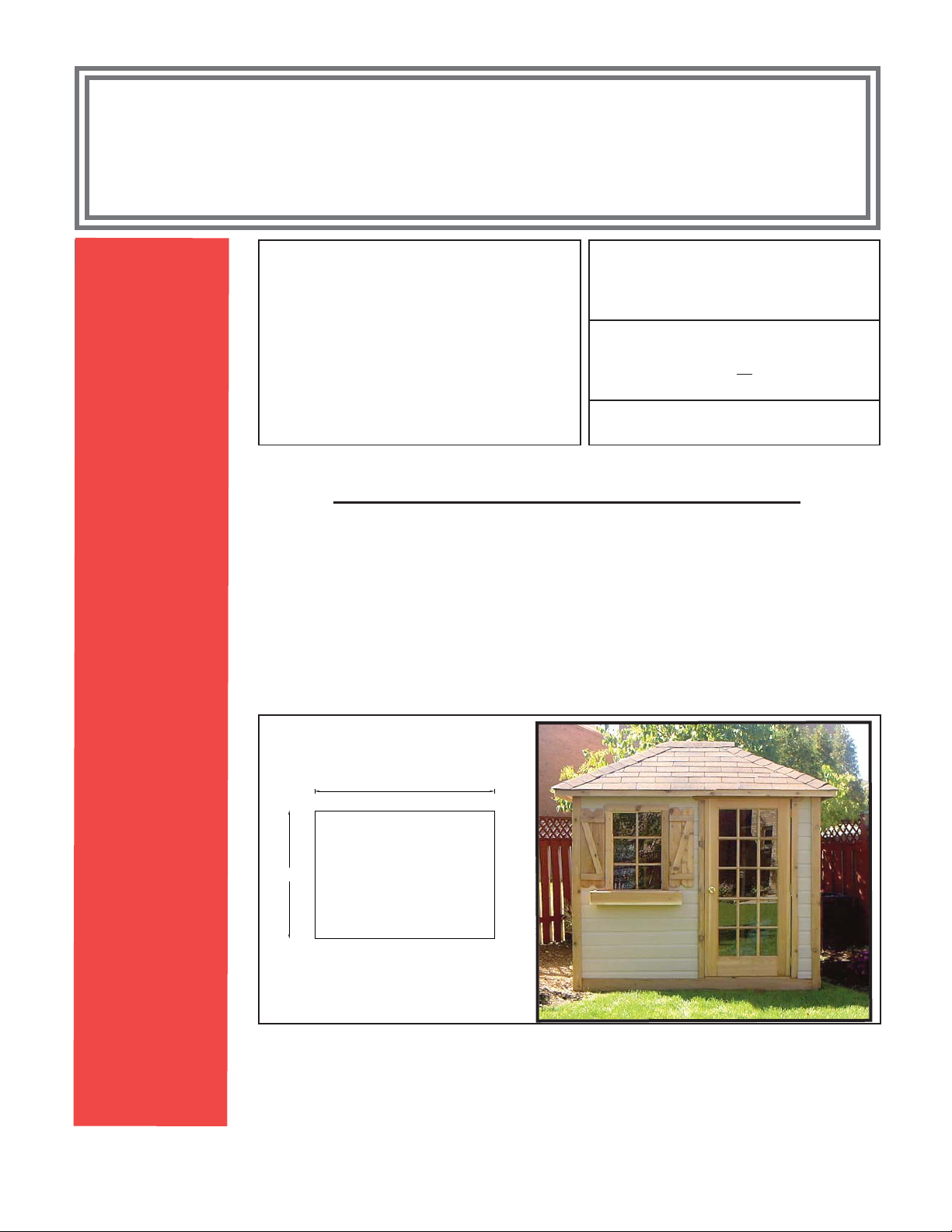
Kenex 653 User manual

36 1/2"
Plan View
96"
96"
6
2
4
Parts List on Next Page
The following pages contain explicit instructions on how to assemble your shed.
Extensive diagrams and complete explanations are offered to make it simple (and fun)
for those who have little or no experience with a project of this nature. Should you have
any questions (or suggestions), please don't hesitate to call our toll free customer ser-
vice line 1-800-606-8911 or (905) 840-9469 in the Toronto area.
Please read the instructions thoroughly and check the con-
tents of this package against the parts list prior to assembly.
Ver. 2.10
624
rev. 07/21/00
Optional Tools:
■ Square / Level (for floor construction)
■ 1/8” Drill Bit
Shingles Required:
bundles asphalt or
bundles cedar shingles.
Required Tools:
❑ Screwgun or
❑ Variable Speed Electric Drill
❑ Screwdriver Bit (Robertson #2)
❑ Hammer
❑ Handsaw
❑ Tape Measure
❑ Step Ladder Note: Assistance may be required to posi-
tion and secure some of the components.
8 x 8 Garden Shed
Assembly Instructions
96"
96 "
6
5
3
Please refer to www.egsheds.com for installation videos and support

Guarantee
The contents of this package are guaranteed to be complete and fit for assembly. Check the contents of the package against this
parts list. If a part is missing or damaged, please call our toll free customer support line@ 1-800-606-8911 for prompt assistance.
Please note that lumber is graded from one side only. Check each part for the most attractive face and use it facing out.
You can visit our website for some general assembly videos - www.egsheds.com
653 - 8 x 8 Hip Roof Parts Checklist
MATERIAL
QTY.
MATERIAL
Dimension
Check
MATERIAL
QTY.
PARTS
Dimension Check
FLOOR PARTS CANEXEL SIDING
2 x 4 PT
2
FACE JOISTS
96"
CANEXEL
14
SIDE WALLS
96"
2 x 4 PT
7
JOISTS
93"
CANEXEL
14
BACK WALLS
48"
2 X 6 P.T.
3
RUNNERS
96"
CANEXEL
4
FRONT WALL
48"
SPRUCE PLY. 5/8"
2
FLOOR SHEATHING
4 X 8
CANEXEL
6
FRONT WALL
12 3/4"
CANEXEL
7
FRONT WALL
11 1/2"
WALL PARTS
2 X 4 SPRUCE
2
WALL PLATES-FRONT
89"
ACCESSORIES
2 X 4 SPRUCE
2
WALL PLATES-BACK
89"
DOOR
1
FRENCH DOOR
71 1/2"
2 X 4 SPRUCE
4
WALL PLATES-GABLE
96"
WINDOW
1
STANDARD WINDOW
25"
2 X 4 SPRUCE
27
STUDS
72"
FLOWERBOX
1
COMPONENTS
2 X 4 SPRUCE
2
WINDOW SPACER
22 1/2"
ROOF PARTS
HARDWARE
2 X 6 SPRUCE
4
HIP RAFTERS
79 1/8"
NAILS
1
3" FRAMING
4 LB.
2 X 4 SPRUCE
4
COMMON RAFTERS
60 3/4"
NAILS
1
1 3/4" SIDING
7 LB.
2 X 4 SPRUCE
4
JACK RAFTERS - LEFT
34"
SCREWS
1
1" #8
7 OZ.
2 X 4 SPRUCE
4
JACK RAFTERS-RIGHT
34"
SCREWS
1
3" #8
75 PC.
2 X 4 SPRUCE
2
TOP PLATES
96"
HINGES
1-PAIR SOLID BRASS HINGES
3 1/2"
2 X 4 SPRUCE
2
TOP PLATES
89"
HANDLE
1
LOCK SET
6 X 6
1
HUB
1 1/2"
1./2" PLYWOOD
5
ROOF BOARD
13" x 96"
1/2" PLYWOOD
2
ROOF BOARD
4 x 8
TRIM PARTS
CEDAR
4
EAVE FASCIA
60" @ 3 1/2"
CEDAR
4
GABLE FASCIA
60" @ 3 1/2"
CEDAR
4
FRONT/BACK CORNERS
84" @ 3"
CEDAR
1
TOP DOOR CASING
46" @ 2 3/8"
CEDAR
4
GABLE CORNER TRIM
84" @ 2 3/8"
CEDAR
1 TRIM STRIP 84"
@
2 1/2"
CEDAR
2 SIDE DOOR CASING 72"
@
2 3/8"
CEDAR
1 TOP DOOR JAMB 36 1/2"
@
3 1/2"
CEDAR
2 SIDE DOOR JAMB 71 1/4"
@
3 1/2"
1 x 6 CEDAR
4 EAVE SOFFITS 60"
1 x 6 CEDAR
4 GABLE SOFFITS 60"
1 x 6 CEDAR
2 GABLE WALL SKIRT 96"
1 x 6 CEDAR
2 FRONT/BACK SKIRT 96"

C A
B
G
C
E
A
F
D
A
F
A
E
G
C
B C A
- 4 - Side Fascia 1 X 3 1/2" x 60"
- 4 - Side Soffits 1 X 6 X 58 3/8"
rev. 02/09/00
- 4 - Frnt. & Bk. Fascia 1 X 3 1/2" x 84"
- 4 - Frnt. & Bk. Soffits 1 X 6 X 84"
- 3 - 4' Roof Panels
- 6 - 13" Roof Panels
8 - Common Rafters 2 x 4 x 61 1/8"
61 1/8"
C
1 - Ridge Beam 2 x 6 x 49 1/2" - D
2 - Roof Plates 2 x 3 x 48" - E
2 - Roof Plates 2 x 3 x 96" - F
2 - Roof Plates 2 x 3 x 91" - G
-
Parts Checklist and Identification Guide - 8 x 8 Roof
Parts List Hip Roof Framing Plan
-
4 - Common Rafters - 2 x 4 x 60 3/4”
top view
5 1/2"
7/8"
-
4 - Hip Rafters 2 x 6 x 79 1/8"
22.5°
top view
7 1/4"
-
8 - Jack Rafters 2 x 4 x 34"
(4 lefts and 4 rights)
C , D
30°
34"
side view
1 1/2"
bird's mouth
5 1/2"
7/8"
top view
left
right
top view
page B
-
1 - Hub - E
-
Roof Plates - 2 x 4 x 89” - F
-
Roof Plates - 2 x 4 x 96” - F
B
C
D
EA
F
30°
A
side view
60 3/4”
1 1/2"
side vie
w
B
79 1/8"

A) General Instructions and Helpful Hints
Please read the instructions BEFORE beginning assembly
Assembly Instruction Organization
The assembly instructions are organized into ten sections. It is strongly recommended that you
assemble your shed in the order presented. Our experience shows that assemblers meet with the
most success when all the parts in the kit are identified and sorted according to the section where
they will be needed prior to assembly. Please refer to the parts checklist on the front cover.
Marking the Plates
The framing dimensions for stud placement given in these instructions are "on center" measure-
ments. The distances shown are measured from the end of the plate to the middle of the stud.
Studs are 1 1/2" wide, so the edges of the stud are 3/4" on each side of center. When laying out
the plates it is often convenient to mark the stud center first, and then make a mark 3/4" away on
one or both sides of the center mark. Indicate the center mark with an "X" so as not to confuse it
with an edge mark.
When marking plates for the walls, both the top and bottom plates can be marked at the same
time by laying them side by side. Use a square to transfer the marks from one plate to the other.
Screwing and Nailing
When screwing or nailing be careful not to set the fastener too close
to the edge, or the end, of a piece of wood. Corners and casings
should have 3" between a fastener and the end of the piece to pre-
vent splitting. As an added precaution, a pilot hole may be drilled for
screws using an 1/8” drill bit.
When nailing the canexel siding to the 2x4 framing follow the
nailing line along the top of each piece. Where the siding is covered
by trim you can place a couple of nails on the face per piece.
rev. 08/09/00 Page 1
3/4"
24"
48"

Squaring a Frame
To square a frame, measure the diagonals (from corner to corner each way), checking that the two
measurements are the same. If they are not, push or pull the corners accordingly so that the two
measurements become the same.
Measurement A
should equal
Measurement B
Recommended Finish
Treat the exposed parts of your shed with a minimum of two coats of a transparent natural or
coloured opaque finish. A quality brand name finish is available at the retailer where you pur-
chased your shed.
This treatment is required in order to validate your manufacturer’s warranty.
A Word about Pool Cabanas
If you intend to use your shed as a facility to house gas-fired pool heating equipment, be sure to
consult with your local gas service person on the placement of your equipment before erecting the
shed. This will ensure that all clearances are adhered to, and that you are able to position the roof
trusses so that they don't interfere with the stack on your gas heater.
A Note on Lumber Dimensions and Wood Properties
Throughout the instructions, reference is made to various lumber dimensions. Please remember
that planing at the sawmill has reduced the size of dimensioned lumber such as 2x3, 2x4, 2x6,
1x8, 1x6 etc. These materials are 1/4" to 1/2" thinner and narrower than stated (ie 2x3 is actually
1 1/2" x 2 1/2", 1x6 is 3/4" x 5 1/2"). In cases where a depth or width is given for material that we
have machined (trim, door casing, etc.), the measurements are usually as stated. All of the parts
in your kit have gone through a quality control process in our plant, but keep in mind that wood is
a natural material and is prone to swelling and shrinkage. Therefore, the size of some of the parts
may vary slightly from the dimensions given. This may result in some minor joint variations, but
should not be cause for concern. When you are sorting the parts in your kit, you may wish to set
aside the straighter studs for use as door studs and corner studs. When assembling parts, consid-
er which face or edge of the piece looks best and keep that side exposed.
rev. 01/31/00 Page 2
B
A

The following pages contain explicit instructions on how to assemble your shed.
Extensive diagrams and complete explanations are offered to make it simple (and fun)
for those who have little or no experience with a project of this nature. Should you have
any questions (or suggestions), please don't hesitate to call our toll free customer ser-
vice line 1-800-606-8911 or (905) 840-9469 in the Toronto area.
Please read the instructions thoroughly and check the con-
tents of this package against the parts list prior to assembly.
Parts Checklist:
❑ 2 -
❑ 7 -
❑ 2 -
❑ 3 -
❑
bag
❑
bag
Plates - 2 x 4 x 96"
Joists - 2 x 4 x 93"
Floor Sheeting Panel 4'x8'
Pressure Treated Runners
8’ long
3" Nails
1 3/4" Nails
Required Tools:
❑
Hammer
❑
Tape Measure
Optional Tools:
■
Square / Level
Note: Assistance may be required to posi-
tion and secure some of the components.
8 x 8 Floor
Assembly Instructions
8'
8' Top Vie
w
Ver. 5.10
204
rev. 08/08/00

flush here
Site Preparation
1) The site you choose for your shed should be well drained and free from puddling.
2) The site must be properly leveled. It is recommended that any sod be removed prior to
leveling and black plastic sheeting or landscaping fabric covered with gravel be put down
before assembly of the floor. This will help keep moisture away from the floor and discourage
the growth of grass under the shed.
Floor Assembly
1) Lay out the joists and plates out on their edges
as shown above. flush here
2) Attach each stud to the plates using two - 3" nails for
each end of the stud. Ensure that the top of the stud stays
flush with the plate.
3) Repeat steps 1 and 2 for second section
rev. 03/28/99
2 - 3" nails
page 4
16"
32"
48"
64"
80"
7
j
oists
plate

4) Once the floor framing is complete, square the floor by measuring the diagonals (from
corner to corner each way), checking that the two measurements are the same. If they are
not, push or pull the corners accordingly so that the two measurements become the same.
Measurement A
should equal
measurement B
5) On the bottom of the floor, place the runners on their face, 6" from the edge of the floor. Attach
using two - 3" galvanized nails per joist.
6) Flip completed frame over and position it on the patio stones or footings. We recommend that
the patio stones or footings be leveled as much as possible to avoid excessive shimming. Add
cedar shims or blocks between the patio stones and the runners to level the frame. Re-check all
sides after raising any one side. Guard against possible sag in the middle of the floor.
1'x 2'
patio
stones
rev. 03/28/99
runners
page 5
A B

7) Position one of the floor panels ensuring that the edge of the panel stays flush with the
outside edge of the outer joist and the front and back plates. The inner panel edge
should be centered on the fourth joist. The edges of the panel will assist you in
keeping the floor square. Secure the sheet with two - 1 3/4" nails at each outside corner
and one nail at each inside corner.
Panel Alignment
Detail
flush here
rev. 08/09/00 page 6
Floo
r
Panel
Floor panel
centered on
fourth joist

8) Position the second floor panel flush with the first. Secure the sheet using one - 1 3/4"
nail in each corner. Finish the floor by nailing both panels about every 8" to all the joists
and plates.
You're now ready to begin the construction of your shed.
rev. 03/28/99 page 7

flush here
3)
Front Wall Assembly (Door on Right)
1)
Lay out the two 89" plates and the six studs on edge as shown below.
2)
Attach each stud to the plates using two - 3" nails for each end of the stud. Ensure that the top
of the stud stays flush with the plate.
flush here
2 - 3" nails7
7 1/2"
3)
Nail the studs twice to the plate using 3" nails. Ensure that the
studs stay flush with the plate at the top and bottom.
4)
Position the window spacers (2 x 4 x 22 1/2") as shown in
the detail below. Using 3" nails, nail each spacer twice
through each stud, ensuring that the spacer stays flush.
Window Spacer
Positioning Detail
rev. 04/30/2014 page 8
31 1/2"
44"
81 1/2"
89"
6 1/2"
3"
nails 34 1/2" 3"
nails

1 cour
48"
3 cour
12 3/4"
3 cour
48"
6) Position the first 48" piece (see detail above) so that they overhang the bottom plate
by 3/4". The siding overhangs end stud (dotted line) by approximately 3 1/2" and remains
flush with inside of door opening and windows. Fasten the first two pieces to the frame using
1 3/4" nails. Apply the next 2 courses, working up to the bottom of the window. Measure
the distance between the siding and the top of the upper plate as each course is being
applied to ensure that the siding remains parallel with the frame. Cheat on spacing as required
to ensure that each subsequent course is aligned with the top plate. Once you reach the
bottom of the window, begin applying the smaller 12 3/4" pieces (3 courses) and finish with 1
course of 48" siding. Apply the 11 1/2" pieces to the non-window wall. Trim the last course to
overhang the top plate by 3/4". The top of the window frame may need to be cut out of the 2nd
last course.
trim to overhang top plate by 3/4"
Siding overhangs end stud (dotted line) by approximately 3 1/2"
Siding overhangs outside plate 3/4"
s
e
48"
s
es
s
es
12 3/4" 12 3/4"
48"

flush here
3)
Front Wall Assembly (Door on Left)
1)
Lay out the two 89" plates and the six studs on edge as shown below.
2)
Attach each stud to the plates using two - 3" nails for each end of the stud. Ensure that the top
of the stud stays flush with the plate.
flush here
2 - 3" nails
10 1/2"
3)
Nail the studs twice to the plate using 3" nails. Ensure that the
studs stay flush with the plate at the top and bottom.
4)
Position the window spacers (2 x 4 x 22 1/2") as shown in
the detail below. Using 3" nails, nail each spacer twice
through each stud, ensuring that the spacer stays flush.
Window Spacer
Positioning Detail
rev. 04/30/99 page 9
6 1/2"
3"
nails 34 1/2" 3"
nails
34 1/2"
47"
81.5
89"

5)
Flip to frame over so that the door opening is on the left.
page 10

12 3/4" 12 3/4"
48"
1 cou
r
48"
3 cou
r
12 3/4"
3 cou
r
48"
48"
se
ses
ses
7) Position the first 48" piece so that it overhangs the bottom plate
by 3/4". The siding overhangs end stud (dotted line) by approximately 3 1/2" and remains
flush with inside of door opening and windows. Fasten the first piece to the frame using
1 3/4" nails. Apply the next two courses, working up to the bottom of the windows. Measure
the distance between the siding and the top of the upper plate as each course is being
applied to ensure that the siding remains parallel with the frame. Cheat on spacing as required
to ensure that each subsequent course is aligned with the top plate. Once you reach the
bottom of the window, begin applying the smaller 12 3/4" pieces (3 courses) and finish with 1
course of 48" siding. Apply the 11 1/2" siding pieces to the non-window wall. Trim the last course to
overhang the top plate by 3/4". The top of the window frame may need to be cut out of the 2nd
last course.
rev. 04/30/14
trim to overhang top plate by 3/4"
Siding overhangs end stud (dotted line) by approximately 3 1/2"
Siding overhangs outside plate 3/4"

4) Back Wall Assembly
1)
Lay out the two back wall sections as shown below.
2)
Attach each stud to the plates using two - 3" nails for each end of the stud. Ensure that the top
of the stud stays flush with the plate.
rev. 04/30/99 page 12
16"
32"
45 1/2"
61 1/2"
77 1/2"
91"

3)
Once framing is complete, square the wall as shown in the general instructions on page 2.
4)
There are 14 - 48" pieces of canexel siding required for this wall. Position the two 48"
bottom pieces of canexel siding so that they overhang the
bottom plate by 3/4" and the end studs by 3 1/2". The joint between the two 48" pieces of siding
will fall on the stud located at the 45 1/2" mark of the plate. Fasten the first piece to the frame
using 1 3/4" nails. Measure the distance between the siding and the top of the upper plate as
each course is being applied to ensure that the siding remains parallel with the frame. Cheat on
spacing as required to ensure that each subsequent course is aligned with the top plate. Trim
the last course so that it overhangs the top of the top plate by 3/4".
rev. 04/30/99 page 13
Siding overhangs end stud by approximately 3 1/2"
Siding
overhangs
bottom plate
3/4"
trim to overhang top plate by 3/4"

5)
Gable Wall Framing (left and right sides)
1)
Using 3" nails, nail the studs to the plates on 16" centers as shown below.
2)
Square wall the as described in page 2 of the general instructions.
page 14

4)
Turn the gable wall over and then re-check squareness.
5)
There are 7 - 96" pieces of canexel siding required for each gable wall. Position the 96"
bottom piece of canexel siding so that it overhangs the bottom
plate by 3/4" and is flush with the end studs. Fasten the first piece to the frame using 1 3/4"
nails. Fasten the rest of the siding pieces. They should be flush with the outside edges of the
end studs. Again, measure the distance between the siding and the top of the upper plate as
each course is being applied to ensure that the siding remains parallel with the frame. The last
piece should be trimmed flush with the top plate.
flush with frame flush with frame
rev. 02/23/96 page 15

fasten inside corne
r
with 3" nails
p
a
g
e 16
6)
Erecting the Walls -
1)
Starting with the gable wall that is most convenient, lift the wall into position as shown below.
Center the wall on the floor so that both ends are flush with the floor (if there is any overhang,
make it equal on both ends). Use scrap packaging to brace the wall diagonally from the floor to
the edge of the wall.
2)
With one person outside pushing the bottom of the
wall tight against the edge of the floor, fasten the wall
by nailing the bottom plate to the floor at 16" intervals.
overhang, if any
should be equal
on both sides of
the floor
nail through bottom
plate every 16" with
3" nails
floor
Be sure to adequately support the
gable wall before proceeding
3)
Slide the back wall into place ensuring that the corner is tight with the gable wall.
4)
Adjust the wall sections so that the top plates are flush with each other (this may require you to
temporarily shim one of the walls). With one person pushing the corner tight, fasten the corner
together from the outside by nailing seven - 1 3/4" nails through the panel
overhang into the gable corner stud.
Reinforce the corner from the inside
by using 3" nails at the top, middle
and bottom.
rev. 01/28/00
Re-check the floor before erecting the walls. It is very important that
the floor is flat and level to insure proper installation of the roof.
flush here
gable wall
top plate
wall to
p
p
late
scrap packaging
material
Table of contents
Other Kenex Garden House manuals