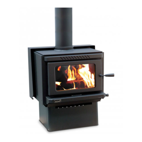
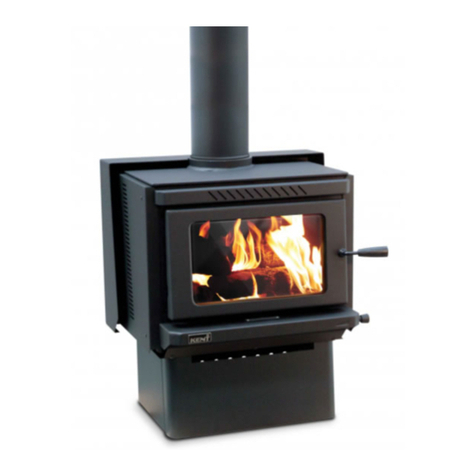
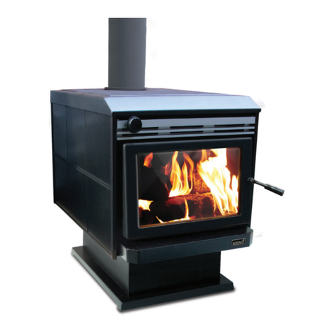
KENT Cardrona Manual

INSTALLATION & OPERATING
INSTRUCTIONS
Clean Air Freestanding Wood Fires
1. This Kent freestanding wood re must be installed by an approved installer, ideally
registered with the New Zealand Home Heating Association. Do not allow any
makeshift or compromising installation methods as this could result in a house re.
This Kent freestanding wood re must be installed according to these instructions.
2. A Building Consent from the Local Authority must be obtained before installing
this wood re, and we suggest that the Insurance Company covering building
insurance be advised of the installation.
3. This Kent freestanding wood re, when installed according to these instructions,
complies with the provisions of AS/NZS 2918-2001 “Installation of Domestic Solid Fuel
Burning Appliances”.
4. The clearances given in these instructions are necessary to prevent overheating
of nearby combustibles and drying out of the house structure. They may not be
reduced without authorisation.
5. Important: Read all instructions carefully before starting installation. Failure to follow
these instructions could result in a re hazard, and may void warranty.
RETAIN THESE INSTRUCTIONS FOR FUTURE REFERENCE
Important: the installer or seller must leave these instructions with the purchaser
GENERAL INFORMATION
General Information ........................ 1
Specications ................................... 2
Installation ...................................... 4-6
Operation ....................................... 6-8
Maintenance .................................... 9
Replacement Parts ................... 10-11
Warranty .......................................... 12
CONTENTS

2
SPECIFICATIONS
External re dimensions (mm) Performance
Model Model No. Width Depth Height Average
emissions
Average
efciency ECAN NO *
Cardrona KWF295-6960 535 490 648 0.80g/kg 69% 165498
Oxford KWF295-6961 535 490 648 0.80g/kg 69% 165500
Benmore KWF295-6962 535 490 648 0.80g/kg 69% 165499
Haast KWF295-6950 575 560 730 0.98g/kg 66% 144660
Murchison KWF295-6952 575 560 730 0.98g/kg 66% 144662
Aspiring KWF295-6951 575 560 730 0.98g/kg 66% 144661
Ruapehu KWF295-6965 760 588 718 0.54g/kg 66% 191312
* ECAN NO = Environment Canterbury authorisation number. TABLE 1
N
N
Minimum Installation Clearances (with ue shield) mm Hearth Clearances (mm)
Model Model No. A B C* D E F G H J K L M N
Cardrona KWF295-6960 135 350 300 130 120 270 610 395 795 855 1140 585 1000
Oxford KWF295-6961 135 350 300 130 120 270 610 395 795 855 1140 585 1000
Benmore KWF295-6962 135 350 300 130 120 270 610 395 795 855 1140 585 1000
Haast KWF295-6950 160 360 300 130 190 320 645 500 835 960 1340 640 1160
Murchison KWF295-6952 160 360 300 130 190 320 645 500 835 960 1340 640 1160
Aspiring KWF295-6951 160 360 300 130 190 320 645 500 835 960 1340 640 1160
Ruapehu KWF295-6965 150 200 300 100 170 315 580 540 960 913 1375 640 1180
* Fuel loading opening to end of floor protector.
Wall Clearances Corner Clearances FIG. 1
TABLE 2
MINIMUM INSTALLATION CLEARANCES
Description Model No.
Standard - 4.2m KWF298-7005 Tested to AS/NZS 2918, Appendix F, ARS report No;02/649
Energy Saver - 4.2m KWF298-7006 Tested to AS/NZS 2918, Appendix F, ARS report No;02/649
Sloping Ceiling - 4.2m KWF298-7354 Tested to AS/NZS 2918, Appendix F, ARS report No;14/2718
RECOMMENDED FLUE KITS FOR KENT FREE STANDING WOOD FIRES

3
Single story ue installation options
(side elevation)
Extra ue components available
Model No. Description
KWF298-7005 Kent standard ue kit 4.2m
KWF298-7006 Kent energy saver ue kit 4.2m
KWF298-7354 Kent sloping ceiling ue kit 4.2m
KWF298-7005 KWF298-7354KWF298-7006
Model No. Description
KWF298-6033 Kent single length stainless steel ue 150 x 1200mm
KWF298-6022 Kent stainless steel ue reector
KWF298-6029 Kent stainless steel ue twin pack 150mm
KWF298-6049 Kent black stainless steel ue twin pack 150 x 1200mm
KWF298-6051 Kent oor penetration 200/250mm diameter
KWF298-6053 Kent 360 degree ue pipe guard
KWF298-6328 Kent stainless steel hat and cowl
KWF298-6614 Kent extension ue 150-200-250 - 1200mm
KWF298-7025 Kent galvanised ue 200 x 1200mm
KWF298-7026 Kent galvanised ue 250 x 1200mm
KWF298-7351 Kent black ue 150 x 1200mm

4
FREESTANDING WOOD FIRE INSTALLATION
To adequately install a Kent freestanding wood re the following items are required: an
assembled wood re, a oor protector, a ue system and a suitable ashing system for ashing
the roof penetration.
An insulating oor protector is not required for the Kent freestanding wood re, but a single layer
ash oor protector of non-combustible material must be used. The oor protector must extend
under the appliance and not less than 300mm in front of the fuel-loading and ash removal
openings. The width of the oor protector shall not be less than the width of the appliance and
shall extend not less than 200mm from each side of any ash removal or fuel-loading openings.
Select a location for the wood re, considering the minimum clearances required (Refer Fig.1, table 2, ).
Place the wood re into the desired position and plumb for the ceiling and roof penetrations.
Allow for 150mm diameter ue pipe, 200mm diameter inner casing and 250mm outer casing.
Check the proposed route of the ue to ensure it is clear of roof trusses and rafters in the ceiling
space or other obstructions. It may be necessary to move the location of the wood re to
ensure this.
Once the location is conrmed, the wood re must be restrained against movement due to
earthquakes. The Kent freestanding wood re is restrained by xing the wood re to the oor
with two bolts of 6mm minimum diameter through the holes provided in the plinth base, through
the oor protector and oor. For solid concrete oors, use 8mm DYNABOLTS® or similar, with a
minimum depth of engagement into the oor of 50mm.
STANDARD FLUE INSTALLATION
Cut a 260mm square hole for the passage of the ue and casings through the ceiling. Trim
timber as necessary and reframe to x 250mm outer ue casing at ceiling height.
Extend plumb line up to roof and cut a hole for the passage of the 250mm ue casing to pass
out through the roof.
Position starter section of 250mm Ø galv ue casing with swaged end up and bottom ush
with the underside of the ceiling. Fix in position with adequate screws tted from inside the ue
through to the framing of the 260mm square opening in the ceiling at the 4 intersecting points.
Back off each screw 5mm so each xing point has a 5mm gap between 250mm Ø ue casing
and 260mm timber framed hole.
Start with the black sections of s/s ue. Join the required number of 150mmØ ue pipes together
by inserting the swaged end of the upper piece into the plain end of the lower piece so the
ue will terminate in the desired position (See Fig.2). Drill and x each length with 3 stainless
steel rivets or self-tapping screws. It is important that each ue joint is sealed with commercially
available ue sealing compound, including the join between re and rst section of ue pipe.
Before tting the ue to the re, place the ceiling plate over re spigot ensuring it is the right
way up.
The 150mm Ø s/s ue sections can either be lowered from the top fully assembled onto the re,
or fed up from the bottom a length at a time ensuring all joints are sealed and xed properly.
Slide the 200mm Ø inner casing/s into place crimped end up, between the outer casing and
the 150mm Ø ue pipes. Slide down so the bottom ue spacer of the 200mm Ø section sits on
the crimped seat of the 250mm Ø starter ue casing. Extend the 200mm Ø ue casing/s up until
it is through the roof and between 200mm and 600mm from the top of the 150mm Ø ue that is
nished in the desired position. Trim ues as required.
Extend up 250 Ø outer casing/s as required noting that the slip section supplied with the standard
ue kit is the last casing to be added this section is adjustable slide in position and secure so the
top of this section is 180mm below the top of the 150 Ø ue.
Fit a suitable ashing over the ue and roof penetration hole to ash the outer casing to the
roof. Seal and x ashing to roof and outer casing with an appropriate waterproof seal.
Place the top ue spacer bracket in position and tighten. Slide weather cowl over ue pipe until
it sits rmly on spacer bracket. Fit the rain hat cowl. NOTE: it must be removable for cleaning.

5
DOOR HANDLE AND DOOR
The door handle is pre-tted and should not require any
adjustment on assembly of the re.
To ensure the door is shutting correctly cut a plain piece
of paper about 50mm wide and place between the
open door and the door frame. Close the door and try
to pull the piece of paper out. If the paper can be freely
pulled out, the door will need to be adjusted so when the
door and handle is in the locked closed position pressure
is applied to the paper strip ensuring the door is sealed
correctly.
If the handle has too much sideways movement the
back nut on the hinge screw will need to be released. Tighten the hinge screw with an Allen
key until the desired movement is achieved (not too tight, not too loose), then re-tighten the
back nut to hold screw in position.
Any adjustment required to maintain the correct t of the door is made at the door catch pin
on the right side of the door lip. To adjust the t of the door catch, loosen the lock nut and turn
the catch pin to loosen or tighten the t. Re-tighten the lock nut (Refer Fig.3).
FOR MORE INFORMATION, REFER TO THE INSTALLATION INSTRUCTIONS INCLUDED WITH THE FLUE KIT.
Before the wood re is used, ensure that a Compliance Certicate (supplied by
a Registered Installer and/or Territorial Authority Inspector) is obtained for the
user. We encourage initial demonstrations on how to light and operate the re to
ensure the user can condently operate the re for safe and efcient performance.
Where the ue terminates more than one full section above the roof penetration, it must be
restrained with guy wires or bracing support bars for stability in high wind conditions.
NOTE: The ue pipe shall extend not less than 4.6m above the top of the oor protector.
The ue cowl must be at least 0.6m above the highest point of the roof, if within 3 metres of the
ridge. The ue cowl must be at least 1m above the roof penetration if more than 3 metres from
the ridge (Refer Fig. 2).
No part of a building, or any adjacent object, may be above ue in a circular area of 3 metres
from the ue exit.
These heights are given as a minimum, and in actual practice the presence of surrounding
structures, trees, fences, etc. may necessitate additional ue height for satisfactory performance.
FIG. 2
3m 3m
3m
More than 3m
0.6m
1m min
or less
Increase as
necessary
until nothing
is within 3m of
top of ue
Increase from
1m until clear
within 3m of
top of ue
FIG. 3

6
TOPOGRAPHY OF THE LAND
Given that the topography of the land and atmospheric conditions vary considerably from
house to house, it is possible for a wood re ue to comply with the minimum requirements
set out in Fig.2 but still fail to extend upward far enough to establish ambient updraft. It is not
uncommon for replaces in houses that are surrounded by hills or trees, or that are located by
large bodies of water to need more ue height than the minimum required by code.
WIND CONDITIONS
Wind causes pressure changes inside as well as outside a house. The design of the house can
inuence the pressure environment around and in your home, the effect of wind on the home
can be complex and unpredictable. Care needs to be taken to ensure the ue termination is in
a good clear position. Your installer should be able to give advice on the best ue termination
position for your situation. Problems associated with wind noise or draft are almost never caused
by the wood re itself and in general a ue that penetrates the roof near the peak and is more
than 600mm above the ridge is unlikely to be affected by wind.
PRESSURE DIFFERENTIAL, VENTING AND EXTERNAL AIR INTO THE
BUILDING
Negative house pressure is a common problem that can cause wood burning appliances to
have trouble lighting and performance issues, in some cases causing smoke to be spilled back
into the room. Kitchen and bathroom exhaust fans air-conditioning units, and well-sealed,
insulated homes are more likely to have a negative pressure problem. Larger homes with
multiple levels are also likely candidates, however any house can have a negative pressure
problem. Care needs to be taken at the design or installation stage to ensure the building has
adequate ventilation to ensure draft in the ue system is always to the outside.
OPERATION
Thank you for purchasing a Kent wood re. Used and maintained correctly, it will provide you
with many years of warmth in your home. Kent wood res have been the main source of heating
for many Kiwi homes, for over 40 years.
Please ensure your installer completes and signs the warranty registration card
in this booklet. We encourage you to read the warranty conditions and draw
your attention to improper fuel use.
FIREWOOD
Modern clean burning wood res are designed to burn seasoned dry natural soft wood only,
such as pine.
The moisture content of the wood affects the performance of your wood re greatly. The most
important thing you can do to operate your wood re correctly is to use the correct seasoned
dry wood. All types of seasoned natural wood will burn in your wood re, but your wood re is
tuned to burn seasoned clean, dry soft woods.
Fossil fuels such as coal are not suitable. Do not burn garbage or large quantiles of paper,
cardboard or similar materials. Do not use chemically impregnated timber, reclaimed wood
from wet environments and do not use drift wood. These corrode the components of the wood
re and ue systems reducing the life of your wood re.
Important: Kent freestanding wood res with a wood box are designed for temporary wood
storage only. Store your “ready-to-use” rewood away from the wood re while in use. If rewood
is placed near or under the wood re it must be there for reloading use only, and be rotated
through often to stop the rewood becoming tinder dry and a potential re safety hazard.
Handy Hint: When preparing rewood for use, store it in an open shed exposed to wind. If
stored in an enclosed garage or shed it will take longer to dry out.

7
DO NOT BURN TREATED TIMBER
DO NOT BURN WET OR UNSEASONED WOOD
LIGHTING
On initial light up, the presence of smoke may be noticed. This is normal and will dissipate
quickly. DO NOT BURN YOUR WOOD FIRE TOO QUICKLY TO BEGIN WITH. Allow several small res
to build up a layer of ash in the wood re, and cure the paint before using maximum power.1.
Adjust the air control knob, until it is fully open.
2. Place several pieces of crumpled newspaper in the base
of the rebox, and criss-cross with 8-10 pieces of dry split
kindling. Stack several pieces of dry split rewood no
greater than 30cm in length on top of the kindling.
3. Ignite the paper and leave the door slightly ajar (resting it
on the latch). Let the re establish itself for 4-5 minutes,
then open the door and add some more pieces of wood.
Do not leave the re unattended during this process.
4. Close the door fully, but leave the air control fully open until the wood is well alight
and burning brightly.
Note: It may be necessary in some cases to leave the door ajar for longer periods and use
more small kindling in order to establish enough heat to warm up the ue. Only when the ue is
sufciently warm to create the necessary draft to maintain the re may the door be fully closed.
It may take trial and error to nd a lighting procedure that suits your situation.
NORMAL OPERATION ONCE THE FIRE IS ESTABLISHED
The Kent wood re requires fresh air for optimal burning, and this must come from outside the
house. A normal house will allow enough air in through incidental openings to satisfy this. We
recommend that a source of air be located near the wood re for best performance. This can
be simply a window that is left ajar while the wood re is in use. If this is not possible, and the
house is particularly air-tight, a vent may need to be installed next to the wood re to provide
the air required. Lack of air will lead to a wood re that is hard to light and get going, or in bad
cases, to smoke spilling back into the room.
While an air control is tted, it is recommended that, for the cleanest operation, this is left fully
open and the amount of heat generated is adjusted by the amount of fuel that is used. The
heater burns cleanest when it is running at a high rate.
Once the re is well established, the output can be regulated by the amount of wood that is
used.
To reload the re, open the air control fully, and then open the door. Note that the re burns
hottest at the front of the rebox and so there may be unburnt wood at the back when it
comes time to reload. This is normal. Rake through the contents to move any unburnt wood
forward and then place the desired amount of wood into the rebox. Close the door.
The view of the ame through the glass door will give you the best indication of how your wood
re is performing. In order to accomplish maximum combustion performance, the re should
give a rolling, boiling ame pattern. At reduced setting the ame will be slower.
For all practical purposes, the air control should be fully open when there is unburnt wood in the
wood re. Fire holding periods may be increased by turning down the air control, this is at the
cost of greater emissions and creosote production. At low settings, creosote may condense on
the glass, reducing the visibility of the re. The best indication that the re is operating correctly
is that the glass remains clean, without build-up of black or brown deposits. Some whitish bloom
on the glass is normal and does not generally indicate a fault in operation.
The way you burn your wood re will also determine what is happening up the ue. Continued
burning at high rates with a good clean ame will minimise soot and creosote deposits in the ue.

8
FOR FIRST FIRE
All Kent wood res are nished in a high temperature quality stove paint. The paint has not
been fully cured until it has been heated. If the re is run too hot, too fast, the paint will burn off
before it has had a chance to fully bond to the steel. When the re is rst used, it should be run
on “low” for the rst 4 hours to allow the paint time to fully cure.
CLEANING OUT THE WOOD FIRE
Your wood re should require minimum cleaning. If the wood re is operated correctly, and
according to the instructions most of the ash will be consumed by the re and a bed of ash will
be maintained that does not build up to any great extent.
If you nd that you have to clean out ashes every day or so, it indicates that the wood re is not
being operated correctly. Either excessively wet wood, unseasoned wood or foreign materials
are being burnt, or the air control is being turned down too much.
Don’t clean out the rebox completely during the heating season. Leave about 25mm of ash
in the bottom of the rebox after cleaning. These ashes in the bottom of the wood re assist the
burning process, by insulating the rebox and allowing air circulation under the re bed.
When emptying ashes use a metal container with a tight tting lid. Do not use this container for
any other purpose. The closed container of ashes should immediately be taken outdoors to a
location well away from any combustible materials, pending nal disposal. If the ashes are to
be disposed of by burial in the garden or otherwise locally dispersed, they should be retained
in the container until they are completely extinguished and cold. This may take several days.
CREOSOTE FORMATION AND NEED FOR REMOVAL
We recommend the ue of your wood re is inspected before use at the start of each heating
season and also periodically during the season. When you are able to operate the wood re
without creating creosote deposits, the interval between inspections may be increased, but
the ue must always be inspected and cleaned at least once a year.
The ue should be swept by a professional chimney sweep to remove any build-up of creosote
and soot. A professional sweep should also advise of any problems that may be detected in the
inspection of the ue and offer advice on any repair and replacements. Your Kent wood re requires
minimal maintenance, and will keep its good looks for a long time with just a little attention.
RUST
Your Kent wood re is manufactured using steel components. Due to the extreme operating
temperatures and inconsistent fuel that wood res are subjected to, a small amount of rusting over
time on the inside of the re box is normal. Without adequate care it is realistic to expect that the steel
re box and internal components will show signs of corrosion.
All steel, including stainless steel requires a level of care and protection to retain its appearance. No
steel is immune to corrosion and neither is it maintenance free.
If your re box and internal components are showing signs of more than a small amount of surface
rust, and a water leak can be eliminated, moisture in the re box can only be due to the environment
the re is installed in, and or, through the fuel that is being used.
Seasoned wood is a very vague term as it depends on how the wood has been kept and stored
since it was felled. Just because a log was felled 2 years ago, does not mean that it is seasoned
enough to be considered “good wood” and suitable re wood.
Visual inspection takes a lot of experience to tell if a piece of wood is sufciently seasoned and dry
enough to be “good wood”. Wet or unseasoned wood is not good for heat output as it produces more
smoke. The moisture released from wet wood combined with the smoke is in most cases corrosive.
Purchasing a moisture meter is an inexpensive way to test how dry your wood is. Always test a new
load of re wood to gauge if it is “good wood”. This will help determine how your re wood needs
to be handled - use now, to be aired or stored for next season.

9
CLEANING
The exterior surfaces of the wood re should be cleaned when needed with a damp cloth and
non-abrasive cleaner. Use of caustic or abrasive cleaners will damage the nish on the wood
re. If, due to continued burning at low temperature, the door glass is dirty, use a paper towel
moistened with water and dipped in the cold ashes from the re to lightly scrub the inside of the
glass. Remember that a properly operated wood re will keep the glass clean by itself.
LUBRICATION
The door hinges, door handle spindle and air slide mechanism should be lubricated periodically
with a suitable high temperature grease. Do not use too much as this can melt and drop down
onto the hearth staining it.
RE-PAINTING
All Kent wood res are nished in high temperature paint. If marks and scratches occur, or
the paint is damaged by over ring or aggressive cleaning agents the appliance can easily
be touched up by using stove paint. Any rust or other stubborn marks that may appear can
be cleaned up and removed with the help of a steel wool pad and hot soapy water, then
repainted if necessary. Touch up paint is available from your Kent retailer. Any unprotected
steel surface left exposed in an environment where moisture may sit on it for extended periods
will require cleaning and care to maintain a quality appearance. Without adequate care it is
realistic to expect that steel may show signs of corrosion.
If the re is not in use for extended periods and you want to protect the surface of your re,
sparingly wipe some extra virgin cooking oil onto the steel with the aid of a paper towel or rag.
Buff off with a clean rag or new paper towel until no reside is left. This will protect the steel and
make it easier to clean in the future (do not apply any oil to the ue pipes). Only clean ue
pipes with fresh clean water and a damp cloth, or dust with a dry clean cloth.
SERVICE AND MAINTENANCE RECORDS
MAINTENANCE
Date Maintenance

10
The air tube in your Kent wood re is an important part of the appliance and helps ensure a
clean, efcient and controllable burn. However, air tubes are a consumable item and are
designed to be replaced as they are likely to degrade with use due to the exposure to the
extreme heat of the re.
The life of the air tube will depend on what is burnt in the re, how hot the re usually burns and
also the ash level. If the ash level is allowed to build up means hot embers are in closer proximity
to the tube, increasing the temperature exposure. Keep ember levels to the recommended
maximum height of 3cm below air tubes.
Replacing air tubes:
1. Remove bricks from both sides
2. Remove the pin from the end of the old tube
3. Slide tube to one side; this will release the opposite end
4. Pull released end up and towards the door and remove
5. Reverse process for new tube
KENT AIR TUBES
REPLACEMENT PARTS
Replacement parts must be original Kent parts. Maintenance required should be carried out
by qualied service people. Please consult your Kent retailer for their details. The wood re
should not be modied in any way except in accordance with instructions supplied by Kent.
Top front
KWF299-6905
Top rear
KWF299-6906
Air Tube Pin
KWF299-6900
KWF299-6903
All Fires
Cardrona, Oxford & Benmore Haast, Aspiring, Murchison & Forbes
Air Tube Spacer
KWF299-6257
All Fires
KWF299-7235
Ruapehu

11
KENT BAFFLES
原图号/物料号
比例
共 张 第 张 用于第 张
数量
FPI(China) LTD. Canature
開能
上海开能壁炉产品有限公司
工艺
审核
批准
设计
日期
版本号 更改描述
签名
年月日
日期
日期日期
M
M
5
43
42
590
25
320
450
640
105
20
275
12- 4
40
M-M
1 : 7
Q
Q
47.5
133.7
66.9
307.9
316.3
600
335
550
150
430
265
73.1
48.1
5
30
515
1
技术要求:
1、未注公差按GB/T1804-2000 m级执行;
2、锐角倒钝,去除飞边毛刺;
3、未注尺寸参考3D造型。
KWF295-6965
顶部隔热板接口图
材料
1:10
KWF295-6965总装
0~30mm±0.2mm;>30~100mm±0.5mm;
>100~500mm±1.0mm;>500~1000mm±2.0mm;
>1000mm±5.0mm;ALL HOLES±0.2mm。
2018/10/16
王从坦
Dimensions (mm): 400 x 208
KWF299-6190
Includes Promat bricks
Dimensions (mm): 480 x 200
KWF299-7043
Dimensions (mm): 640 x 340
KWF299-7233
Ruapehu
Haast, Aspiring, Murchison & Forbes
Cardrona, Oxford & Benmore
The bafe in your Kent wood re is an important part of the appliance and helps ensure a clean,
efcient and controllable burn. However, bafes are a consumable item and are designed to
be replaced as they are likely to degrade with use due to the exposure to the extreme heat of
the re.
The life of the bafe will depend on what is burnt in the re and how hot the re usually burns.
Replacing bafe:
1. Remove front air tube by pulling locking pin out of air tube spacer slide ring on the left top
side. Slide spacer ring to the right and slide air tube horizontally to the left. Right hand side
of the air tube will drop out of the keyed side.
2. Swing air tube out through door.
3. Lift bafe plate up off side support rails and pull forward 40mm. Push one side up as high as
you can while letting the other side drop over the side support rail.
4. Keep at a 30° angle and remove it through the door.
5. Reverse process to install new bafe. And air tube.
6. Ensure bafe is sitting rm against back.
The re bricks in your Kent wood re are an important part of the appliance and helps ensure
a clean and efcient burn. However, re bricks are a consumable item and are designed to
be replaced as they are likely to degrade with use due to the exposure to the extreme heat of
the re.
The life of the re bricks will depend on what is burnt in the re and how hot the re usually burns
and also any damage sustained from wood not being positioned correctly.
At the risk of damaging the re box, re bricks should be replaced when they are damaged
enough that they no longer remain in place and cannot perform their intended function. Fire
bricks which are only cracked but still remain in place do not need to be replaced and are
safe to use.
KENT FIRE BRICKS
Dimensions (mm):
4 - 220 x 115 x 28
2 - 221 x 221 x 25
2 - 229 x 220 x 25
KWF299-6123
Dimensions (mm):
2 - 240 x 190 x 25
2 - 245 x 177 x 25
KWF299-7089
Dimensions (mm):
5 - 150 x 160 x 25
2 - 150 x 234 x 25
KWF299-7234
Ruapehu
Haast, Aspiring, Murchison & ForbesCardrona, Oxford & Benmore
Note: For all other re parts please contact your Kent dealer.

12
WARRANTY
KENT 15 YEAR WARRANTY FORM
Please keep this copy for your records.
MODEL:…………………………………………………....................................................
SERIAL NUMBER:……………………………………………….........................................
RETAILER:…………………………………………………………….................................
PURCHASE DATE:………………………………………………..........................………..
INVOICE NUMBER:……………………………………....................................................
(Please keep your invoice attached to your warranty record)
INSTALLER NAME:…………………………………….………………......................…….
DATE INSTALLED:…………………………………………………..............................…...
NZ HOME HEATING
ASSOCIATION NUMBER:………………………….…………………......................…….
INSTALLER SIGNATURE:………………………………………………........................……
5088-02/19
Kent products are distributed by: Aber Holdings Ltd T/A Aber Living, 17 Mainstreet Place, Te Rapa, Hamilton 3200
Free Phone: 0800 161 161 | Free Fax: 0800 163 163 | www.aberliving.co.nz
Product specications are at date of publication and are subject to change without notice.
Please read this warranty carefully and keep it, and your purchase receipt in a safe place.
You must produce the required Kent product warranty registration information and proof of
purchase in the event of any warranty repair being required.
WARRANTY TERMS & CONDITIONS
Kent agrees to replace, or repair as necessary any part of the appliance which is proven at the time of
delivery, or within the warranty periods shown below to be defective through faulty materials or workmanship.
This warranty is for normal domestic use. Your Kent wood re is warranted for up to 15 years, with the exception
of the following parts; door glass, door and glass seals, re bricks, ue, secondary air systems and bafe plates,
which all have a 12 month (part only) warranty.
The warranty does not cover damage or failure due to incorrect or faulty installation, misuse, negligence,
water damage, burning improper fuel or environmental conditions. Any unauthorised alteration, modication
or substitution of any part of this appliance or use of this appliance not in accordance with the instructions
supplied, will render this warranty void.
Your Kent wood re must be installed in accordance with the manufacturers instructions and with the
appropriate approved ue system. Installation must comply with applicable standards, regulations and local
by-laws. Failure to do so will void any warranty offered in its entirety.
If the appliance needs repair and is installed outside the normal service area (25km) of the nearest authorised
service agent the purchaser is responsible for any additional expenses incurred. In the event that an appliance
needs to be replaced, the warranty does not extend to any consequential materials required or additional
expenses incurred.
In the event of a whistling air tube caused due to environmental circumstances, Aber Living will replace the air
tube. The warranty does not extend to related installation, labour or travel costs.
All claims against the warranty must be directed in the rst instance to the store of purchase. Any repairs
undertaken without the manufacturers authority will invalidate this warranty.
In order to claim on the warranty, you will need to supply; proof of purchase, installation, servicing details and
a completed warranty form (below).
Your Kent wood re warranty is transferable on the sale of the home where the wood re is installed. Nothing
in this warranty is intended to limit any conditions of the warranty right or remedy pursuant to the Consumer
Guarantee Act 1993, except to the extent permitted under the Act. Your Kent wood re is intended for
domestic use only and the warranty is not valid for wood res to be used for business purposes. Kent reserves
the right to alter or amend specications or designs of its product without prior notice.
This manual suits for next models
7
Table of contents
Other KENT Indoor Fireplace manuals
Popular Indoor Fireplace manuals by other brands

Astria Fireplaces
Astria Fireplaces Villa Vista Installation and operation instructions

Dru
Dru G20 Installation manual & users guide

Napoleon
Napoleon Ascent Multi-View Series Installation and operation manual

Masterbuilt
Masterbuilt GMFP20 Assembly, care & use manual

Muskoka
Muskoka Bellamy MTVS2547SE instructions

Riello
Riello RS 810/EV O2 BLU Modulating operation