Introduction
Your
choice
of
this
product
indicates
that
you
are
a
devotee
of
excellence
in
sound
reproduction.
We
appreciate
your
patronage
and
take
pride
in
the
long
tradition
of
quality
components
that
our
company
repre-
sents.
So
that
you
can
get
the
most
out
of
your
unit,
we
suggest
that
you
take
the
time
to
read
through
this
manual
before
you
hook
up
and
operate
your
system.
This
will
acquaint
you
with
the
operating
features
and
system-connection
considerations,
so
that
your
listening
pleasure
will
be
enhanced
right
from
the
start.
You
will
notice
that
in
all
aspects
of
planning,
engineering,
styling,
operating
con-
venience
and
adaptability,
we
have
sought
to
anticipate
your
needs
and
desires.
Keep
this
manual
handy
for
future
reference.
For
your
records
Record
the
serial
number,
found
on
the
back
of
the
unit,
in
the
spaces
designated
on
the
warranty
card,
and
in
the
space
provided
below.
Refer
to
the
model
and
serial
numbers
whenever
you
call
upon
your
dealer
for
informa-
tion
or
service
on
this
product.
Models
Serial
Number
Unpacking
Unpack
the
unit
carefully
and
make
sure
that
all
accesso-
ries
are
put
aside
so
they
will
not
be
lost.
Examine
the
unit
for
any
possibility
of
shipping
damage.
If
your
unit
is
damaged
or
fails
to
operate,
notify
your
dealer
immediately.
If
your
unit
was
shipped
to
you
directly,
notify
the
shipping
company
without
delay.
Only
the
consignee
(the
person
or
company
receiving
the
unit)
can
file
a
claim
against
the
carrier
for
shipping
damage.
We
recommend
that
you
retain
the
original
carton
and
packing
materials
for
use
should
you
transport
or
ship
the
unit
in
the
future.
Contents
(NtFOUUCHON
4atinisaiiatisisin.
meen
ard
2
A
Before
APDIYING
POWER
0.
ce
eeeeceeee
cnet
ee
eneteeeeeeeeees
3
AX
Safety.
PrOCAUTIONS:
«ivi
jorBschxed
Swkeerstane
noc
ienin’
3
Z\
IMPORTANT
SAFEGUARDS
....
4
System
connections
........
en
AO
Controls
and
indicators
.....
re
2
Remote
control
ait
vnc
as
cise
ise
fecanttntedediees
13
DiSDlayisiicdteiennpen
ek
Glos.
caaadetuaeantety
enti
20
On-screen
character
display
oo...
ccccecceeeeteceereeeeeees
21
Operating
INStrUCtiIONS
ccc
ceeeeeseree
eee
eneeetetteeeeeenes
23
Caution:
Read
the
following
pages
marked
in
A\
carefully
to
keep
your
safety.
Playback
an
aUudiO
COMPONENT
oo...
eecceeee
teens
Recording
an
audio
SOUICE
oe.
eeeeeeeeseeeteeseeneeees
Dubbing
an
audio
SOULCE
oo...
eeeeeteeteeeeeteeteees
Playing
back
a
video
source
Recording
a
video
source.
........
Independent
audio/video
recording
SunrOund
fects
recente
chet
coeahew
eerie
Pith:
EGit
fUNGON
42.2860
2h
atic
nea
Ra,
Inscasecof-
difficulty.
2/cAaar
ame
Meine
SPECIFICATIONS:
ccc:
ssi
cade
accetusatitausnmtitteeasy
nel
meists
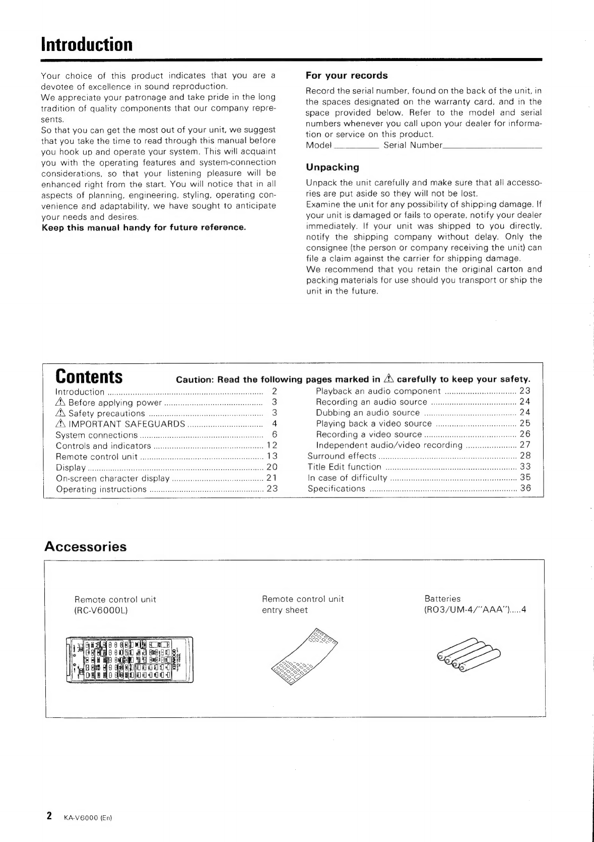
Accessories
Remote
control
unit
(RC-V6000L)
Remote
control
unit
entry
sheet
Batteries
(RO3/UM-4/"AAA").....4
2
KA-V6000
(En)


