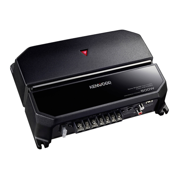
KAC-PS1D/X1R
3
COMPONENTS DESCRIPTION
●AUDIO UNIT (X09-8560-10)
Ref. No. Application / Function Operation / Condition / Compatibility
IC1 µ-com Overall control.
IC3 DC/DC converter driver Generates the gate waveform for switching.
IC5 (2/2) Comparator Compares the analog signal with the triangular wave and generates the PWM waveform for
the minus output-side amplifier of the BTL.
IC6 (1/2) Comparator Detects ASO. Compares current with voltage to detect short in the output.
IC6 (2/2) Comparator Detects the resonance waveform that is caused when the plus and minus terminals are
shorted in the vicinity of the SP terminals, and protects from the short.
IC7 (1/2) Comparator Detects over current with the waveform shaped in IC17 and sends the result of the detection
to the µ-com and the TR used to control the D-class amplifier.
When SP+ or SP- terminal output is shorted to the ground, the current in the + power supply
IC7 (2/2) Comparator and that in the - power supply are unbalanced.The unbalance in the current is converted into
DC voltage in Q176 and Q177, and when the voltage exceeds the preset value the output is
reversed and the protection function is activated.
IC10,11 Isolation AMP Removes the common mode noises in the input signal.
IC12 Buffer AMP Buffer AMP for RCA output.
IC13 (1/2) Signal amplification
Amplifies the output voltage between the SP + and SP - terminals and generates the NF signal.
IC13 (2/2) Signal amplification
Amplifies differences between the input and feedback signals.Initial stage of the D-class amplifier.
IC14 (1/2), Comparator, Triangular wave generation.
IC20 (1/2) Signal amplification
IC14 (2/2) Comparator Compares the analog signal with the triangular wave and generates the PWM waveform for
the plus output + side amplifier of the BTL.
IC15,16,21 NAND gate To gate pulse of the D-class amplifier.
IC17 NAND gate Retains the pulse width and keeps holds a certain width when IC6 and IC7 (2/2) detect its
individual over current.
IC18 Signal amplification Amplifies and rectifies the output voltage at the SP + terminal, and generates DC voltage that
is proportional to the output.
IC19 (1/2) Signal amplification Amplifies the potential differences caused by current running in the GND pattern, and sends
it to the µ-com to obtain current.
IC19 (2/2) Signal amplification Amplifies the DC offset at the SP + terminal, and applies to the DC servo.
IC20 (2/2) Signal amplification
Generates the inverted waveform of the triangular wave that is generated in IC14 (1/2) and IC20 (1/2).
IC22 Filter
Filters and rectifies the resonance waveform that is caused when the plus and minus terminals
are shorted in the vicinity of the SP terminals, and sends the resultant DC voltage to IC6 (2/2).
IC24 Signal amplification When 1Ωload is detected, lowers the voltages at pins 1 and 7 and decreases the signal
clipping level in order to limit the SP output.
IC55~57 BassBoost circuit Boosts the signal with the operations from the remote control.
(Remote control operation) GAIN=0~+18dB, fc=40~100Hz
Q1,2 POWER ON SWITCH
Turns ON/OFF DC/DC converter power supply in response to the output from pin 8 of the µ-com.
Q3~5 5V constant voltage It is used as the constant voltage power supply of 5V for the µ-com and the SW5V.
power supply
Q6 SW5V control Turns ON/OFF 5V to the SW5V line in response to the output from pin 20 of the µ-com.
Q7 Pcon over voltage control Blocks the ON signal to the Pcon and places the Pcon in the OFF condition when the battery
voltage is too high.
