manuals.online logo
Brands
  1. Home
  2. •
  3. Brands
  4. •
  5. Kenwood
  6. •
  7. Car Receiver
  8. •
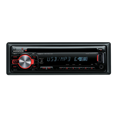
  9. Kenwood KDC-MP538U User manual

Kenwood KDC-MP538U User manual

Other manuals for KDC-MP538U

2

This manual suits for next models

7

Other Kenwood Car Receiver manuals

Kenwood X34-59 User manual

Kenwood

Kenwood X34-59 User manual

Kenwood KDC-C521FM - CD Changer With RF Modulator User manual

Kenwood

Kenwood KDC-C521FM - CD Changer With RF Modulator User manual

Kenwood KDC-2031SA User manual

Kenwood

Kenwood KDC-2031SA User manual

Kenwood KRC-478R/RV User manual

Kenwood

Kenwood KRC-478R/RV User manual

Kenwood KRC-960 User manual

Kenwood

Kenwood KRC-960 User manual

Kenwood DDX6017 User manual

Kenwood

Kenwood DDX6017 User manual

Kenwood KDC-5090B User manual

Kenwood

Kenwood KDC-5090B User manual

Kenwood TH-G71A User manual

Kenwood

Kenwood TH-G71A User manual

Kenwood KDC-BT60U User manual

Kenwood

Kenwood KDC-BT60U User manual

Kenwood EZ700SR User manual

Kenwood

Kenwood EZ700SR User manual

Kenwood KDC-BT665U User manual

Kenwood

Kenwood KDC-BT665U User manual

Kenwood KVT-839DVD User manual

Kenwood

Kenwood KVT-839DVD User manual

Kenwood KDC-3011 User manual

Kenwood

Kenwood KDC-3011 User manual

Kenwood KDC-MP832U User manual

Kenwood

Kenwood KDC-MP832U User manual

Kenwood KVT-717DVD User manual

Kenwood

Kenwood KVT-717DVD User manual

Kenwood KDC-BT43U User manual

Kenwood

Kenwood KDC-BT43U User manual

Kenwood KRC-108S User manual

Kenwood

Kenwood KRC-108S User manual

Kenwood KRC-309S User manual

Kenwood

Kenwood KRC-309S User manual

Kenwood KDC-BT8044U User manual

Kenwood

Kenwood KDC-BT8044U User manual

Kenwood KRC-152LA User manual

Kenwood

Kenwood KRC-152LA User manual

Kenwood KDC-BT530U User manual

Kenwood

Kenwood KDC-BT530U User manual

Kenwood DPX302U User manual

Kenwood

Kenwood DPX302U User manual

Kenwood KRC-235 User manual

Kenwood

Kenwood KRC-235 User manual

Kenwood KDC-MP535U User manual

Kenwood

Kenwood KDC-MP535U User manual

Popular Car Receiver manuals by other brands

Linear Series LS5050 Operation and installation manual

Linear Series

Linear Series LS5050 Operation and installation manual

Sony XR-CA430X Service manual

Sony

Sony XR-CA430X Service manual

T+A Elektroakustik K1 CD-RECEIVER operating instructions

T+A Elektroakustik

T+A Elektroakustik K1 CD-RECEIVER operating instructions

SoundMax SM-CDM1052 instruction manual

SoundMax

SoundMax SM-CDM1052 instruction manual

Xtrons HD107HD user manual

Xtrons

Xtrons HD107HD user manual

Mopar RB3 manual

Mopar

Mopar RB3 manual

Clarion ADDZEST DMZ615 owner's manual

Clarion

Clarion ADDZEST DMZ615 owner's manual

Sony XAV-601BT Specifications

Sony

Sony XAV-601BT Specifications

PIE GM12-POD/S Operation manual

PIE

PIE GM12-POD/S Operation manual

Hyundai H-910H instruction manual

Hyundai

Hyundai H-910H instruction manual

Sony XR-C6100 Service manual

Sony

Sony XR-C6100 Service manual

Sony CDX-L600X - Fm/am Compact Disc Player Installation/connections

Sony

Sony CDX-L600X - Fm/am Compact Disc Player Installation/connections

Motorola VWA63 Service manual

Motorola

Motorola VWA63 Service manual

Sound Storm STM93R user manual

Sound Storm

Sound Storm STM93R user manual

Nextar D3201 instruction manual

Nextar

Nextar D3201 instruction manual

Alpine CDE-163BT owner's manual

Alpine

Alpine CDE-163BT owner's manual

Axxera XDMA7600 Installation & owner's manual

Axxera

Axxera XDMA7600 Installation & owner's manual

XM OnyX quick start guide

XM

XM OnyX quick start guide

manuals.online logo
manuals.online logoBrands
  • About & Mission
  • Contact us
  • Privacy Policy
  • Terms and Conditions

Copyright 2025 Manuals.Online. All Rights Reserved.

SERVICE MANUAL
This product uses Lead Free solder.
This product complies with the RoHS directive for the European market.
© 2008-4 PRINTED IN JAPAN
B53-0631-00 (N)429
KDC-MP538U/MP6039/MP6539U
KDC-W6041U/W6141UY
KDC-W6541U/W6641UY
KDC-X592
CD RECEIVER
TDF SPARE-PANEL
MAIN UNIT NAME TDF PARTS No. TDF NAME
KDC-MP538U Y33-2950-61 TDF-MP86D
KDC-MP6039 Y33-2950-65 TDF-MP6039
KDC-MP6539U Y33-2950-64 TDF-MP6539U
KDC-W6041U Y33-2950-63 TDF-W6041U
KDC-W6141UY Y33-2950-63 TDF-W6041U
KDC-W6541U Y33-2950-62 TDF-W6541U
KDC-W6641UY Y33-2950-62 TDF-W6541U
KDC-X592 Y33-2950-60 TDF-86DX
Mounting hardware assy
(J21-9716-03)
Lever
(D10-7012-04) x2
* DC cord
(E30-6428-05)
* Screw set
(N99-1757-15)
* Escutcheon
(B07-xxxx-xx)
* Carrying case
(W01-xxxx-xx)
* DC cord
(E30-6671-05)
* Screw (4x16)
(N84-4016-48)
* Plastic cabinet assy
(A02-2755-13)
* Remote controller assy (RC-547)
(A70-2085-05)
Battery
(Not supplied)
* Depends on the model. Refer to the parts list.
KDC-MP538U : Panel assy (A64-4436-11)
KDC-MP6539U : Panel assy (A64-4441-11)
KDC-W6141UY : Panel assy (A64-4440-11)
KDC-W6641UY : Panel assy (A64-4438-11)
KDC-MP6039 : Panel assy (A64-4442-11)
KDC-W6041U : Panel assy (A64-4439-11)
KDC-W6541U : Panel assy (A64-4437-11)
KDC-X592 : Panel assy (A64-4435-11)
KDC-X592
KDC-MP538U
KDC-W6541U
KDC-W6641U
KDC-W6041U
KDC-W6141U
KDC-MP6539U
KDC-MP6039
* Screw set
(N99-1790-05)
* Compact disc
(W01-1723-05)
* Cover
(F19-1475-04)
2
KDC-MP538U/MP6039/MP6539U/
W6041U/W6141UY/W6541U/W6641UY/X592
BLOCK DIAGRAM
AM+B
FRONT-END
CD MECHA
PON5V
A8V
A8V
AGC
E-VOL
PRE
MUTE
IC
POWER
PRE OUT
AUX IN
IC451
RDS
DECODER
BU5V
A8V
SERVO+B
UP
BACK
RESET
IC BU5V
u-COM
P-CON
ANT-CON
ACC DET
ILLUMI
BU5V
ILL+B
SW14V
A8V
SW5V
P-CON
ANT CON
ILLUMI
ACC
BACK UP
LINE MUTE
SP OUT
(FL/FR/RL/RR)
FL
RESET SW
LED
BU5V
PON5V
SERVO
A8V
ILL+B
ILL+B
(F/R SW)
WIRED REMOTE
LINE MUTE
LX BUS CONNECTOR
4P
USB5V
to USB u-COM
USB I/F
SW16V
SW16V
SW16V
USB u-COM
PAN5V
BU3.3V
IC1
IC700
IC601
IC501
A322 Q321,322
Q331 J431 CN201
Q407,408
Q401-406
IC301
DME1
Q121
Q141-144
Q145,146
Q151
C151,R152
Q123
Q21,22
Q23,24
IC11
Q141-144
SERVO
+B+B
Q31-34
Q41-44
Q51,52
FDC
Q71,72
FL+B
SW DC/DC
(FL)
(D5V)
DC/DC
SW
PAN5V
HI-SIDE
SW
FL+B
USB5V
VBUS OC
(BT3.3V)
DC/DC
PAN5V BT3.3
Q681,682
Q81,82 IC71
IC211 IC61
IC965
DET
BU/SERGE
SW
EJE/SRC
MATRIX
KEY
ROM
CORRECTIO
ROTARY
ENCODER
REMOTE
CONTROL
DRIVER
LED
FL+B
ED1
S2-6
IC4
S1
S7 IC3
IC602
u-COM
PANEL
LEVEL
SHIFT
AUTHENTICATION
iPod
u-COM
USB Q602,603
Q702,703
IC750
J1
J401
J421
IC700
WH151
SYSTEM
VBUS OC
E2PROM
FST
FM/AM
CD
SPECTRUM
MUTE A
MUTE 0,1,2
WININ OFFSET
MUTE A
PWIC MUTE
for
MPX
RDS
ANALYZER
DC ERR
MUTE 0,1,2
AUX
CH
MUTE C
MUTE C
STBY
PREM/SW M
I2S
I2S
DAC
SWITCH UNIT (X16- )
ELECTRIC UNIT (X34- )
DPU1
CD PLAYER UNIT (X32-6130-00) BOARD
MOTHER
(X34- )
EF
A
C
B
TR COIL
FO COIL
APC
IC4
16.934MHz
CLOCK
IC3
LOADING &
MOTOR
DRIVER
MOTOR
SPINDLE
S2
S1
S3
SLED
MOTOR
DM1
DM2
X1
Q1
RF AMP
SERVO
MP3 DECODER
WMA DECODER
1M bit SRAM
PROCESSOR
AAC DECODER
+
+
+
+
+
CR FILTER
CR FILTER
REVERSAL
CIRCUIT
Q13
BU1.5V REG
IC5
IC6
IC11
SW3.3V REG
SW1.5V REG
LOADING &
VREF
12EJE-SW
LOS-SW
LOE-SW
MOTOR
LO/EJ
A.GND
A8V
A,B,C,E,F
TR OUT
FO OUT
DM OUT
FM OUT
A3.3V
LD
SIGNAL
S.GND
S7.5V
FO OUT
TR OUT
DM OUT
FM OUT
DRV MUTE
SO
SRAMSTB
SI
BUCK
CCE
PIO0
SRAMSTB
BUCK
CCE
PIO0
SO
SI
MRST MRST
C88,R82
C87,R83
R-ch
L-ch L-ch
R-ch
ZDET MUTE L/R
D.GND
D GND
BU1.5V
SW1.5V
SW3.3V
AGND
BU5V
P.ON
PD
BSIF LRCK
BSIF ST REQ
BSIF GATE
BSIF BCK
BSIF DATA
BSIF ST REQ
BSIF GATE
BSIF DATA
BSIF BCK
BSIF LRCK
8EJE-SW
3
KDC-MP538U/MP6039/MP6539U/
W6041U/W6141UY/W6541U/W6641UY/X592
COMPONENTS DESCRIPTION
●ELECTRIC UNIT (X34-588x-xx)
Ref. No. Application / Function Operation / Condition / Compatibility
IC11 Audio8V REF Power Supply Outputs 1.27V.
IC21 REG Power supply for IC700. (USB μ-COM)
IC61 SW REG Power supply for D5V. (To USB and PANEL)
IC71 SW REG Power supply for FL+B. (To PANEL)
IC101 OP-AMP For IC451’s 4V reference voltage supply.
IC211 Hi-side SW Detects USB’s over-current.
IC301 RDS decoder IC Decodes RDS.
IC331 OP-AMP For AGC of spectrum analyzer.
IC451 E-VOL & Source Selector Controls the source, volume, and tone.
IC501 Power IC Amplifies the front L/R and the rear L/R to 50W maximum.
IC601 System μ-COM Controls FM/AM tuner, the changer, CD mechanism, panel, volume and tone.
IC602 Reset IC Lo when detection voltage goes below 3.6V.
IC603 ROM Correction
IC604 Muting Logic IC Controls muting logic.
IC605 Level Shift (3.3V→5V)
IC607 Level Shift (5V→3.3V)
IC700 USB μ-COM USB and CD mechanism control.
IC750 iPod Authentication Coprocessor iPod authentication.
Q11 AUD8V AVR When Q13’s and Q12’s bases goes ON, A8V AVR outputs 8.0V.
Q12 AUD8V AVR SW When Q13's base goes Hi, current is supplied to IC11.
Q13 AUD8V AVR SW When Q13’s base goes Hi, Q12 and Q11 are ON.
Q21,22 BU5V AVR While BU is applied, BU5V AVR outputs +5V.
Q23,24 PON5V When Q24’s base goes Hi, PON5V outputs +5V.
Q31,32 SERVO+B AVR When Q33’s and Q34’s bases go ON, AVR outputs 8V.
Q33,34 SERVO+B SW When Q34's base goes Hi, Q33 is ON.
Q41,42 ILL+B AVR When Q43’s and Q44’s bases go ON, AVR outputs 10V.
Q43,44 ILL+B SW When Q44’s base goes Hi, Q43 is ON.
Q51,52 SW16V When Q9’s and Q34’s bases go ON, voltage is applied. (MAX16V)
Q71,72 FDC+B AVR When Q43’s base goes ON, AVR outputs 9V. (FL filament)
Q81,82 FL+B SW When Q81’s base goes Hi, FL+B outputs 53V.
Q101,102 4VPRE+B When Q104’s and Q105’s bases go ON, 4VPRE+B is output. (MAX12V)
Q103 4VPRE+B Protect When 4VPRE+B has over-current, Q103 turns Q101 off.
Q104,105 4VPRE+B SW When Q105’s base goes Hi, Q104 is ON.
Q121 BU DET SW When the base goes Hi, BU voltage is detected.
Q122 Surge DET SW When the base goes Hi, surge voltage is detected.
Q123 ACC DET SW When the base goes Hi, ACC voltage is detected.
Q141,144 P-CON SW When Q144’s base goes Hi, AVR outputs 14V.
Q142,143 P-CON Protect Protects Q141 when P-CON output is grounded.
Q145,146 Power Antenna SW When Q146’s base goes Hi, power antenna SW outputs 14V.
Q151 Small-lamp DET SW When the base goes Hi, small-lamp is detected.
4
KDC-MP538U/MP6039/MP6539U/
W6041U/W6141UY/W6541U/W6641UY/X592
Ref. No. Application / Function Operation / Condition / Compatibility
Q321,322 AM+B SW When Q322’s base goes Hi, AM+B is output.
Q331 AGC For spectrum analyzer.
Q401~406 Pre-out Mute SW When a base goes Hi, pre-out is set to mute.
Q407,408 Pre-out Mute Driver When a base goes Lo, mute driver is turned on.
Q601 CD SRAM STB SW When the base goes Lo, SRAM is standby.
Q602,603 Level Shift From system μ-COM (5V) to USB μ-COM (3.3V).
Q681,682 PANEL+5V SW When Q682’s base goes Hi, PANEL+5V is output.
Q683,684 Level Shift From CD mechanism (3.3V) to system μ-COM (5V).
Q702,703 3.3V AVR for IC700 (Flash ROM type) When Q702’s base is Hi, 3.3V is ON.
Q704 SRAM Standby Control Buffer When the base is Lo, SRAM is standby.
Q705 CD LOE LIM SW Buffer When the base is Hi, loading ends.
●SWITCH UNIT (X16-63xx-xx)
Ref. No. Application / Function Operation / Condition / Compatibility
IC1 Panel μ-COM Controls panel.
IC3 Remote Control IC Receives remote control signal.
Q1 Triangle Red LED SW Triangle LED lights when the base goes Hi.
Q3 Blue LED SW (left of VOL) Blue LED brightness control (PWM).
Q4 Blue LED SW (Top on FL & ATT Key) Blue LED lights when the base goes Hi.
Q5 Blue LED SW (Under FL) Blue LED brightness control (PWM).
Q6 Blue LED SW (Multi Key) Blue LED brightness control (PWM).
Q11 VFD Filament Voltage (-) VFD cut-off bias supply (5.0V - 7.5V).
Q21 Blue LED SW Blue LED brightness control (PWM).
Q22 Red LED SW Red LED brightness control (PWM).
Q23 Green LED SW Green LED brightness control (PWM).
●CD PLAYER UNIT (X32-6130-00)
Ref. No. Application / Function Operation / Condition / Compatibility
IC3 4ch BTL Driver Driver for focusing & tracking coil, driver for sled & spindle motor, and operation for disc
loading & ejection.
IC4 Servo DSP with built-in Audio DAC With built-in MP3/WMA/AAC decoder and 1M-bit-SRAM.
IC5 D1.5V REG. Power supply for digital 1.5V.
IC6 D3.3V REG. Power supply for digital 3.3V.
IC11 BU1.5V REG. Power supply for back-up 1.5V.
Q1 APC (Auto Power Control) Drives LD (Laser Diode).
Q13 Inverter Inverts ZDET signal.
D2 Laser Diode Protection Prevents reverse bias which is applied to laser. Laser destruction prevention.
D3,4 Static Electricity Countermeasure Prevents malfunction by static electricity.
COMPONENTS DESCRIPTION
5
KDC-MP538U/MP6039/MP6539U/
W6041U/W6141UY/W6541U/W6641UY/X592
MICROCOMPUTER’S TERMINAL DESCRIPTION
●SYSTEM μ-COM : IC601 on X34- (ELECTRIC UNIT)
Pin No. Pin Name I/O Application
Truth Value
Table Processing / Operation / Description
1 WIRED REMO I Remote control signal input Pulse width detection
2 RDS QUAL I RDS decoder QUAL input
3 S SYS DATA O Data from system μ-COM to SOC 400kHz
3 CD SI O CD mechanism serial output (MP6039)
4 S SOC DATA I Data from SOC to system μ-COM 400kHz
4 CD SO I CD mechanism serial input (MP6039)
5 S SOC CLK I Clock from SOC (SOC is the host) 400kHz
5 CD CLK O Serial clock output (MP6039) f=1MHz
6 BYTE -
7 CNVSS -
8 XCIN - 32768Hz
9 XCOUT - 32768Hz
10 RESET -
11 XOUT - 12MHz
12 VSS -
13 XIN - 12MHz
14 VCC1 -
15 NMI I Not used
16 RDS CLK I RDS clock input
17 PANEL DET I Panel connector ON/OFF detection H: Panel OFF, L: Panel ON
18 SRC KEY I Source key input H: OFF, L: ON
19 RDS DATA I RDS decoder data input
20
CD DRIVEMUTE
O CD motor driver mute output
21 EJECT KEY I Eject key input H: OFF, L: ON
22 PANRST O Panel reset H: Normal, L: Reset
23 CD PIO0 I Communication request from CD mechanism DSP
(Command interface) H: Data requested
24 PON CD I/O CD mechanism power supply control H: Power supply ON, Hi-Z: Power supply OFF
25 F SEL1 I/O SW-REG frequency setting (Bluetooth)
26 PWIC BEEP O Beep output 2kHz / 1kHz
27 TUN SCL I/O Front-end I2C clock input/output MAX: 400kHz
28 TUN SDA I/O Front-end I2C data input/output MAX: 400kHz
29 PAN SYS DATA O Data from system μ-COM to panel UART MAX: 500kHz
30 PAN PAN DATA I Data from panel to system μ-COM UART MAX: 500kHz
31 PAN SYS REQ O
Communication request from system μ-COM to panel
32 PAN PAN REQ I
Communication request from panel to system μ-COM
33~35 NC - Not used Output L fixed
36 PON ILL I/O Panel LED power supply control
FL display bias power supply control
H: POWER ON,
Hi-Z: Panel OFF or POWER OFF
37 NC - Not used Output L fixed
38 PON PANEL I/O Power supply for panel μ-COM
FL display VDD supply
H: POWER ON,
Hi-Z: Panel OFF or POWER OFF
6
KDC-MP538U/MP6039/MP6539U/
W6041U/W6141UY/W6541U/W6641UY/X592
Pin No. Pin Name I/O Application
Truth Value
Table Processing / Operation / Description
39 ROMCOR DET I ROM correction writing request H: Possible to rewrite in ROM correction
(I2C opened)
39 EPM I EPM input while writing
Possible to rewrite in Lo at the start-up
40 CD MOTOR O CD motor control qRefer to the truth value table
41
CD LOE LIM SW
I CD detection (Chucking detection) H: Loading completed, L: No disc
42 CD LOS SW I CD loading detection L: Eject completed
43
CD DISC12 SW
I 12cm disc detection L: 12cm disc
44 PAN SC CON O Panel operation control
CE when system μ-COM program is rewritten H: Normal, L: Panel operation stopped
45 CD LOEJ I/O CD motor control qRefer to the truth value table
46 S SOC REQ I
Communication request from SOC to system μ-COM
47 SOC SSTOP O SOC stop H: Normal, L: SOC stopped
47 CD SRAMSTB O Decoder SRAM standby control (MP6039) L: SRAM standby
48 SOC SRST O SOC reset H: Normal, L: Reset (Bolero)
48 CD RST O CD mechanism μ-COM reset (MP6039) H: Normal, L: Reset
49 S SYS REQ O
Communication request from system μ-COM to SOC
49 CD CCE O CD mechanism chip enable (MP6039)
50 SOC MUTE I DAC mute request H: Mute requested, L: Normal
50 CD MUTE I DAC mute request (MP6039) H: Mute requested, L: Normal
51 PON D5V I/O For USB / FDC 5V power supply control H: ON, Hi-Z: OFF
52 PON I/O Power supply control H: ON, Hi-Z: OFF
53
OEM DISP DATA
I/O External display data
54 OEM DISP CLK I/O External display clock
55 OEM DISP CE I/O External display control request
56 P CON I/O P-CON control POWER ON: H, POWER OFF: Hi-Z,
STANDBY source: Hi-Z
57 ANT CON O Antenna control TUNER source: H, POWER OFF: L,
STANDBY source: L
58 NC - Not used Output L fixed
59 ILLUMI DET I Dimmer illumination detection L: ON, H: OFF
60 VCC2 -
61 MUTE 0 O E-VOL FRONT MUTE control L: Mute ON, H: Normal,
Time constant isolation setting: 10ms
62 VSS -
63 MUTE 1 O E-VOL REAR MUTE control L: Mute ON, H: Normal,
Time constant isolation setting: 10ms
64 MUTE 2 O IC-2 SW MUTE control
L: Mute ON, H: Normal,
Time constant isolation setting: 10ms
(Countermeasure for IC-2 shock noise)
65 LINE MUTE I Line mute detection TEL mute: Below 1V, NAVI mute: Over 2.5V
66~68 NC - Not used Output L fixed
69 MUTE SA I/O IC-2 MUTE A control
Spectrum analyzer mute
L: Mute ON, Hi-Z: Normal,
Time constant isolation setting: 0.5ms
70 PWIC DC DET I DC offset detection
MICROCOMPUTER’S TERMINAL DESCRIPTION
7
KDC-MP538U/MP6039/MP6539U/
W6041U/W6141UY/W6541U/W6641UY/X592
Pin No. Pin Name I/O Application
Truth Value
Table Processing / Operation / Description
71 ACC DET I ACC detection ACC detected: L, No ACC: H
72 BU DET I BU detection BU detected: L, No BU or Momentary power
down or Over-voltage: H
73 LX REQ S I Communication request from slave unit
74 MUTE AFS I/O IC-2 MUTE C control / AFS mute L: Mute ON, Hi-Z: Normal,
Time constant isolation setting: 0.5ms
75 SDAEVOL I/O Data output from system μ-COM to E-VOL Communication speed: 200k-400kHz
75 SDAE2P I/O I2C data for ROM correction Communication speed: 200k-400kHz
76 SCLEVOL I/O Clock output from system μ-COM to E-VOL Communication speed: 200k-400kHz
76 SCLE2P I/O I2C clock for ROM correction Communication speed: 200k-400kHz
77 PWIC MUTE O Power IC mute STANDBY source or Momentary power down:
L, TEL mute: L
78 PWIC STBY O Power IC standby POWER ON: H, POWER OFF: L
79 LX REQ M O Communication request to slave unit
80 LX MUTE I Mute request from slave unit H: Mute ON, L: Mute OFF
81 LX CON O Start-up request to slave unit H: Slave unit ON, L: Slave unit OFF
82 LX RST O Forced reset to slave unit H: Reset, L: Normal
83 MUTE PRE FR O External preout mute F/R 0-bit, Momentary power down: L
84 MUTE PRE SW O External preout mute SUB
(Countermeasure for mute shock noise) 0-bit, Momentary power down: L
85 PON AM I/O AM+B power supply control H: AM received, Hi-z: Other conditions
86 TUN IFC OUT I Front-end IFC-OUT input H: Station detected, L: No station
87 TUN SMETER I S-meter voltage detection
88 RDS NOISE I FM noise voltage detection
89 RDS AFS M I/O Noise detection time constant SW L: AF search, Hi-Z: Normal
90 TYPE 1 I A/D (5-pattern)
91 TYPE 2 I A/D (5-pattern)
92,93 NC - Not used Output L fixed
94 AVSS -
95 NC - Not used Output L fixed
96 VREF -
97 AVCC -
98 LX DATA S I Data from slave unit
99 LX DATA M O Data to slave unit
100 LX CLK I/O LX-BUS clock
Truth value table
qCD motor control
CD MOTOR (Pin 40) CD LOEJ (Pin 45)
Standby L L
Eject H H
Load H L
Brake H Hi-z
MICROCOMPUTER’S TERMINAL DESCRIPTION
8
KDC-MP538U/MP6039/MP6539U/
W6041U/W6141UY/W6541U/W6641UY/X592
●PANEL μ-COM : IC1 on X16- (SWITCH UNIT)
Pin No. Pin Name I/O Application
Truth Value
Table Processing / Operation / Description
1 REMO I Remote control signal input Pulse width detection
2 NC - Not used Output L fixed
3 FL SI1 O FL display serial data output Pulse output
4 NC - Not used Output L fixed
5 FL CLK O FL display serial clock output H: Except when data is written
(Including STANDBY)
6 BYTE - GND
7 CNVSS -
8,9 NC - Not used Output L fixed
10 RESET - Reset Being controlled by system μ-COM
H: Normal, L: Reset
11 XOUT - Resonator 12MHz
12 VSS - GND
13 XIN - Resonator 12MHz
14 VCC1 - Power supply (5V) Connects PAN5V
15 NMI I Not used Input fixed
16~19 NC - Not used Output L fixed
20
LED CONT RTY2
O LED rotary (Multi-key side) PWM output H: LED ON, L: LED OFF
20
LED CONT BLUE
O Vari blue PWM output H: LED ON, L: LED OFF
21 NC - Not used Output L fixed
22 FL BK O FL display blanking control H: FL display OFF, L: FL display ON
23 FL LAT O FL display latch control H: Data through, L: Data latch
24
LED CONT UNDER
O
LED side luminescence (Under FL display) PWM output
H: LED ON, L: LED OFF
24
LED CONT RED
O Vari RED PWM output H: LED ON, L: LED OFF
25 NC - Not used Output L fixed
26
LED CONT RTY1
O LED rotary (VOL side) PWM output H: LED ON, L: LED OFF
26
LED CONT GREEN
O Vari GREEN PWM output H: LED ON, L: LED OFF
27,28 NC - Not used Output L fixed
29 PAN DATA O Data transmission from panel
30 SYS DATA I Data reception from system μ-COM
31 SYS REQ I System μ-COM communication request input H: Data communicated
32 PAN REQ O Panel communication request output H: Data communicatied
33 FL SI2 O FL display serial data output Pulse output
34 NC - Not used Output L fixed
35 CLK IN I/O FL display serial clock input Inputs FL display clock
36~38 NC - Not used Output L fixed
39 ROMCOR DET I ROM correction writing mode H: Authorization to rewrite in ROM correction
(I2C opened)
39 EPM I For rewriting in flash ROM (EPM) Input fixed
40~43 NC - Not used Output L fixed
44 FLASH CE I For rewriting in flash ROM (CE)
45,46 NC - Not used Output L fixed
47
LED CONT FLTOP
I/O LED side luminescence (Above FL display) SW H: LED ON, Hi-Z: LED OFF
MICROCOMPUTER’S TERMINAL DESCRIPTION
9
KDC-MP538U/MP6039/MP6539U/
W6041U/W6141UY/W6541U/W6641UY/X592
Pin No. Pin Name I/O Application
Truth Value
Table Processing / Operation / Description
48 LED CONT TRI I/O Triangle LED luminescence SW H: LED ON, Hi-Z: LED OFF
49,50 NC - Not used Output L fixed
51 SDA I/O
Data transmission and reception for ROM correction
Output except when data is read
52 SCL I/O Clock for ROM correction Output except when clock data is read
53~55 NC - Not used Output L fixed
56 ROTALY2 CW I Rotary (Multi key) B input Pulse width detection
1-pulse/2-click, 15-pulse/360°
57 ROTALY2 CCW I Rotary (Multi key) A input Pulse width detection
1-pulse/2-click, 15-pulse/360°
58 ROTALY1 CW I Rotary (VOL) B input Pulse width detection
1-pulse/2-click, 15-pulse/360°
59 ROTALY1 CCW I Rotary (VOL) A input Pulse width detection
1-pulse/2-click, 15-pulse/360°
60 VCC2 - Power supply (5V) Connects PAN5V
61 NC - Not used Output L fixed
62 VSS - GND
63~70 NC - Not used Output L fixed
71 SC CON I System μ-COM communication
Panel operation control
H: Panel operated,
L: Panel operation stopped
72 NC - Not used Output L fixed
73 KR2 I Key return input q
74 KR1 I Key return input q
75 NC - Not used Output L fixed
76 KS1 I/O Key scan output qSwitches between output-L and Hi-Z
77 KS2 I/O Key scan output qSwitches between output-L and Hi-Z
78 KS3 I/O Key scan output qSwitches between output-L and Hi-Z
79 KS4 I/O Key scan output qSwitches between output-L and Hi-Z
80 KS5 I/O Key scan output qSwitches between output-L and Hi-Z
81~90 NC - Not used Output L fixed
91 SA RST O Reset output for spectrum analyzer H: Reset released, L: Reset
92 SA CLK O Clock output for spectrum analyzer
93 SA IN I Data input for spectrum analyzer
94 AVSS - GND
95 NC - Not used Output L fixed
96 VREF - A/D analog reference voltage Connects PAN5V
97 AVCC - Power supply (5V) Connects PAN5V
98~100 NC - Not used Output L fixed
Truth value table
qKEY MATRIX
KR1 (Pin 74) KR2 (Pin 73)
KS1 (Pin 76) TI AM
KS2 (Pin 77) MENU <<
KS3 (Pin 78) AUDIO PLAY
KS4 (Pin 79) ATT >>
KS5 (Pin 80) N/A FM
MICROCOMPUTER’S TERMINAL DESCRIPTION
10
KDC-MP538U/MP6039/MP6539U/
W6041U/W6141UY/W6541U/W6641UY/X592
● How to enter the test mode
Press and hold the [FNC] and [EJECT] keys and reset.
(While ”----” is being displayed, power can be ON for 30
minutes.)
●How to clear the test mode
Reset, momentary power down, ACC OFF, Power OFF,
detach the panel.
●Test mode default condition
• Source is STANDBY.
• Display lights are all turned on.
• The volume is at 30 (-10dB).
• LOUD is OFF.
• CRSC is off regardless of the availability of switching
function.
• SYSTEM Q is NATURAL (=FLAT).
• BEEP should always function when the key is pressed
briefly.
• AUX is ON
• DISPLAY TYPE is TYPE A, SIDE is Display Tag.
• TUNER source display shall be as shown below:
<For European models> Upper row = PS/Frequency,
Middle row = Spectrum analyzer/Clock, Lower row =
Date
<For models of destination “K” and “M”> Upper row =
SNPS, Middle row = Spectrum analyzer/Clock, Lower
row = Date
• CD/USB source display shall be as shown below:
Upper row = P-TIME, Middle row = Spectrum analyzer/
Clock, Lower row = Date
• SOURCE SELECT shall be “2”.
• Illumination color shall be white as a preset color. (Except
KDC-MP6039)
●Specification of the test mode for tuner source
The frequency of 98.3MHz is received when the [4] key is
pressed in the TUNER FM mode.
(
∗1) Only in the test mode, [1] key, [2] key, [3] key, [4] key,
[5] key and [6] key shall be displayed on the multi-
function key.
1. Press the [FNC] key briefly to make the multi-
function display.
2. Rotate the control knob on the right side and use
the [ ] / [ ] keys to display the target key in the
center.
3. Press the [ ] key briefly to finalize the display.
(
∗2) Perform the same operations as above on the keys,
[1], [2], [3], [4], [5], and [6] of the remote controller.
●TUNER Setup adjustment mode specification
1. Use [FM] / [AM] key to select TUNER band.
2. Press and hold [ ] key for 2 seconds to enter TUNER
adjustment mode. At the same time, set FM receive fre-
quency to 98.3MHz.
3. Use [FM] / [AM] key to change between the adjustment
items.
FM Key FM Key
AM Key
AM Key
AM Key
FM Key
Seek Stop Level adjustment
(manual)
Soft Mute adjustment
Seek Stop Level adjustment
(auto)
(Note) The first item shall be Soft Mute adjustment.
But, in the case of AM band, the first item shall be
Seek Stop Level adjustment (auto) because there
is no Soft Mute adjustment for AM band.
4. Proceed with the following steps for every adjustment
item:
Soft Mute Adjustment
∗This item exists only in TUNER FM. Make adjustment
under the condition when VOLUME=30 and LOUD is
OFF.
(Display) SMD–x___ : Adjustment values, 0~F, are
shown in “x”.
a. Use [ ] / [ ] key to set the value between 0 (18dBu)
and F (36dBu).
b. After the completion of the adjustment, press and hold
[] key for 2 seconds to start writing the adjustment
values in E2PROM. At the successful completion of
the writing, “EP_WRITE” is displayed
Seek Stop Level Adjustment (Auto)
(Display) ATN_4.32V : When at Normal (Local OFF)
(Display) ATL_3.45V : When at Local (Local ON)
Current receive level
←
a. In the band in which Local Seek ON/OFF is selectable,
Press [AUTO] / [TI] key briefly to change between Lo-
cal Seek ON and OFF.
b. Press and hold [ ] key for 2 seconds to make the cur-
rent receive level to be the seek stop level in order to
start writing the adjustment values in E2PROM. At the
successful completion of the writing, “EP_WRITE” is
TEST MODE