LVD-K9200
2
CONTENTS/ACCESSORIES
CONTENTS
ACCESSORIES
............cscccsssssnecesccorsensscensnsnsereceseseseees
2
8.
MPX
balance
and
assist
level
circuit
(X25-5410)
...30
CONTROL
si
fos
chciss
Racssisccscvasbaccetipibeasasecpecdeeestsseseteantee
3
9.
Key
control
LED
lighting
up
circuit
.............
31
REMOTE
CONTROL
OPERATION
...............0:cceeseees
4
10.
Key
operation,
VR
control
and
DISASSEMBLY
FOR
REPAIR
.............::cscsssssseesreeeeees
5
lesson
return
function
control
BLOCK
DIAGRAM
.uuu........c
cece
cece
ceceetenececoncecesseneeseees
7
with
the
microphone
(X25-5410)..............
32
CIRCUIT
DESCRIPTION
ADJUSTMENT
..............:cscccccsssssesssssecssssssesersscecersees
33
1.
Flow
chart
for
disc
starting
............::ccseecees
11
WIRING
DIAGRAM
0...
ccc
cceessassereccssssecenenseees
40
2.
Test
Mode
.......ccccccccccsssecseecesseeescesssceesesseseeeees
14
PC
BOARD
(COMPONENT
SIDE
VIEW)
................
41
3.
Description
of
components
...........:.scesseee
17
SCHEMATIC
DIAGRAM
...........cccssccecescceesseeneeeeeeee
49
_4,
Main
u-com
:
M37451M8-329SP
(X35-,
1C11)
......
24
EXPLODED
VIEW
:
MECHANISM.
................c0c0cecee
69
5.
Sub
u-com
:
uPD75238GJ-088
(X25-,
1€301)..........
26
EXPLODED
VIEW
:
UNIT
uuu...
eeseececssssneneeeensees
73
6.
Z
Servo
(X29-2450)
...........cesesecseessseeeeeetneeeeees
28
PARTS
UIST
iescccesenacivesetides
he
ciccsesiacesccecdesiccsctiasesteceys
75
7.
Vocal
mode
circuit
(X25-5410)
............:cseeeees
29
SPECIFICATIONS
...............cccccsesseeeeenes
BACK
COVER
*Refer
to
the
following
service
manual,
if
need
description
about
item
of
table.
Service
manual
parts
No.
:
DP-950
(B51-4351-00),
LVD-320
(B51-4629-00),
LVD-K101
(B51-4260-00)
[unit
Reftio.
|
PartsNo.
[|
_Funetion
Name
|
Reference
service
manual_|
Reference
page
esr
[en
|
eaters
amp
—SCSC~C~C“~Ss~sSC“‘“‘C‘i
OCC
Die
en
cae
oe
ro
SC
ey
al
Tics
|
cao002am
|
Analog
audio
signal
processor
|
_vb320~+(|_—=P2a_—
Ge]
extes008d
|
Bigial
signal
processor
|
vos
——=«dT=SCi‘i
x35-2120
|
Tics
|
Sws87285
|
Disital
filter
&
D/A
converor_|
_vo-320—=«dY;C(ti‘i
Video
FM
signal
demodulation
|
Lvo-azo
«|=
[Pas
IC4
IC6
IC62
YVL151C
Video
signal
processor
LVD-320
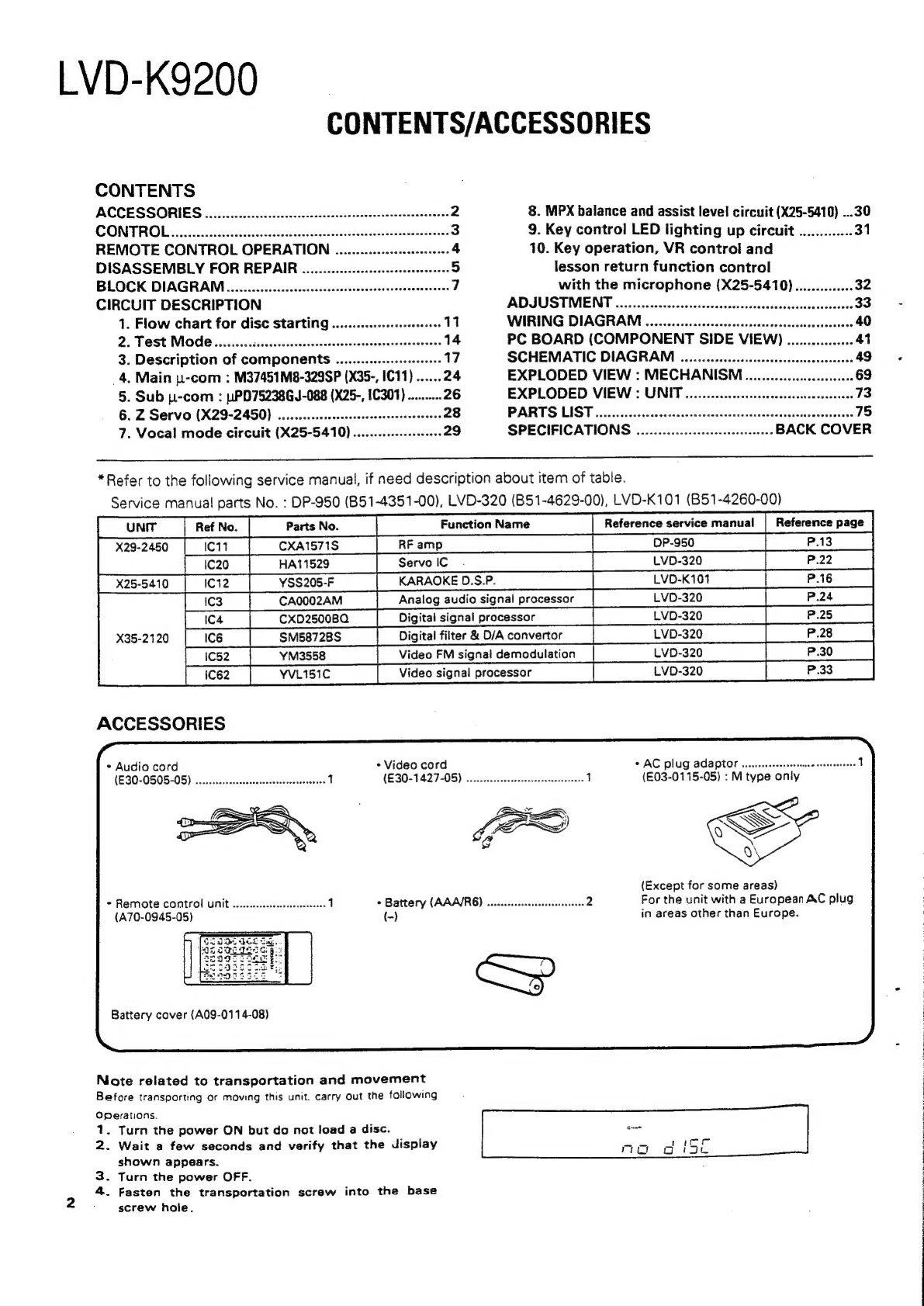
ACCESSORIES
*
Audio
cord
+
Video
cord
¢
AC
plug
adaptor
(E30-0505-05)
(E30-1427-05)
(E03-0115-05)
:
M
type
only
a
aN
4
a
Le
A
ed
~
(Except
for
some
areas)
+
Remote
control
unit
*
Battery
(AAA/R6)
For
the
unit
with
a
European
AC
plug
(A70-0945-05)
(-)
in
areas
other
than
Europe.
Battery
cover
(A09-0114-08)
Note
related
to
transportation
and
movement
Before
transporting
or
moving
this
unit.
carry
Out
the
following
Operations.
1.
Turn
the
power
ON
but
do
not
load
a
disc.
aks
2.
Wait
a
few
seconds
and
verify
that
the
display
Ap
aise
shown
appears.
3.
Turn
the
power
OFF.
4.
Fasten
the
transportation
screw
into
the
base
screw
hole.


