5
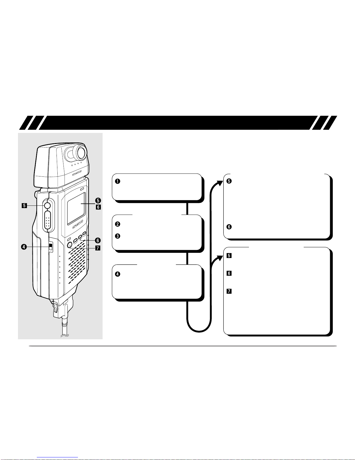
CONNECTION WITH A HANDY TRANSCEIVER
Use the provided cable to connect the VC-H1 with a
handy transceiver.
Note: The VC-H1 functions as a speaker microphone only when
connected with a handy transceiver. You need not switch ON the VC-H1.
1Confirm that the power switches of both the VC-H1
and transceiver are OFF.
2Connect the appropriate end of the provided cable to
the DATA port of the VC-H1.
• To remove the cable from the VC-H1, pull the cable
connector downward while pushing its tabs from both
sides.
3Connect the other end of the cable to the speaker/
microphone jacks on your handy transceiver.
Note: The compatible handy transceivers are TH-26, TH-46, TH-27,
TH-47, TH-28, TH-48, TH-22, TH-42, TH-77, TH-78, TH-79, and TH-G71.
An optional PG-4T cable is available for connecting with a TM-255,
TM-455, TM-733, TM-V7, or TM-G707 transceiver. To make a cable for
connecting with a TS-570 or TS-870 transceiver, you may obtain an
optional connector kit (E59-0407-08) which mates with the VC-H1 DATA
port. For the above options, contact your authorized KENWOOD dealer,
customer service, or service center.
REMOVING/ REINSTALLING THE CAMERA UNIT
Note: Turn OFF the power to the VC-H1 before removing or reinstalling
the camera unit.
To remove the camera unit, first turn it so that it crosses
at right angles with the main unit.
To reinstall the camera unit, first position the port on the
camera unit over the port on the main unit so that the
two units cross at right angles.
Note: The camera unit has a structure that allows the plug assembly to
be slightly moved. This is aimed at absorbing stress to be caused when
the camera unit is turned.
To remove
or