SEER
CONN
So
ia
THANK
YOU!
oii
ccecessscceeeeeeeeeees
Inside
Front
Cover
|
CHAPTER
=
@)]
M5)
GETTING
ACQUAINTED
)
MODELS
COVERED
BY
THIS
MANUAL
nn
cccccceseeccee
ieSinePront
Gover
ape
hogs
ala
te
vot
Me
reek
teltt
en
Ae
ath
EN
Beas
7
FEATURES
ooonccooccoccceeeececceceeceseece
indide
Front
Gover
oe
ee
be
Spevceede
Soh
sedis
besadecsaaesaeee
hes
nitaeaoa
uate
9
NOTICES
TO
THE
USER
o.oo
cccesseeeeeeeeneneeeeaee
i
i
‘
CONE
sepsce
tee
eater
nta
tiie
is
PRECAUTIONS
ccssccessssssssssesssstssssnesesssanetnssen
ee
i
oc
aaa
a
nae
A
Sietasdenecvseeducteaeadaiteses
13
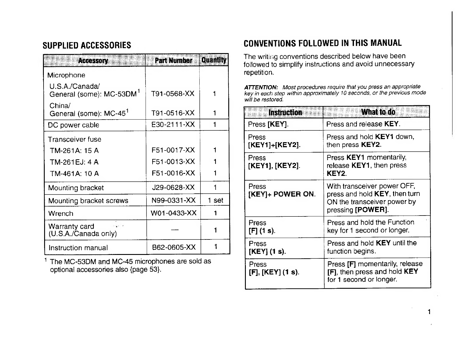
SUPPLIED
ACCESSORIES
......--sesesseesseeesseeerssssreeesens
i
Basic
State
Display
Labels
............ccesesseeeeeesees
13
CONVENTIONS
FOLLOWED
IN
THIS
MANUAL
......
1
Labels
After
Pressing
[F]
...........:cccccssessesssessesees
13
CHAPTER
(1)
Hata
Oe
OPERATING
BASICS
PREPARATION
FOR
MOBILE
AND
FIXED
STATION
OPERATION
SWITCHING
POWER
ON/OFF
....ssscecsssssssseseesesssenee
14
MOBILE
INSTALLATION
PITT
COTTER
TTT
TTT
eT
2
ADJUSTING
VOLUME
Co
EN
leas
a
te
tee
14
Installation
Example
...........
ee
eeeeessessseeseeseeeeeeeaes
2
Installation
Steps
.......eceeceeceeeeeseeeeeeneeseneeeneeseneaees
2
ADJUSTING
SQUELCH
«10...
sseessssessseseesssenessensee
14
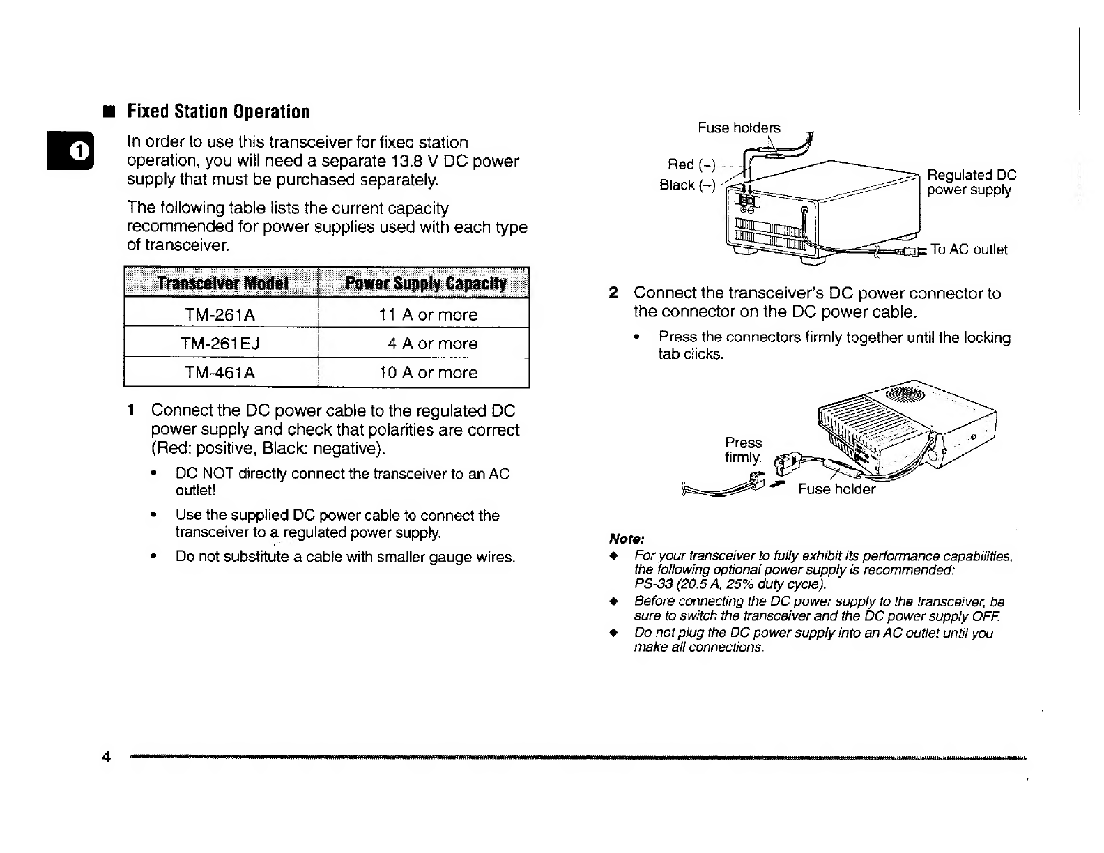
DC
POWER
CABLE
CONNECTION
Bde
siuteddeenth
tates
3
SELECTING
FREQUENCIES
Preece
eC
CCU
RPSe
eer
ee
ress
15
Mobile
Operation
......sc..ccssscessessessessesssssecseesesseeneeece
3
Tuning
COMtrOl
......-ssssssesssessesseeenseeeseeeeensnseenennsee
15
Fixed
Station
Operation
.....c.ccccescsessecsesestesseeeseese
4
Microphone
[UPJ[DWN]
BUItons
«........sseesssee
15
Replacing
Fuses
.......
ec
ecccecsesseeessesseeseereeeereee
5
TRANSMITTING
ue
cece
cccteseeeesseeeesnenreeessseeeneeee
16
ANTENNA
CONNECTION
be
sgt
Ne
asta
aha
red
nee
5
Selecting
Output
POWGS
a
cdiccceccpctvcetsuecsdesaasecvacdeves’
16
ACCESSORY
CONNECTIONS
.....cccccsccccsseessssssssseeess
6
CHAPTER
@)
Mua
ld
External
Speaker
...........cceecseesesseesenseneesseseesenss
6
MENU
DESCRIPTION
.........
eee
seeeseseeeseeeeeenesentees
17
MiCrOphone’
.........
ee
ceeeeeeeeeeeetsstcceesresssesessaeeeeeeenens
6