KeriSystems V-Track User manual

V-Track™ Automatic Long Range Vehicle ID System
Installation Guide
Page 1 of 20 P/N: 01538-001 Rev. G
1.0 System Overview
The Keri V-Track™ System1is similar to the highway toll type systems such as E-ZPass®2or FasTrak®2in that they
both operate in the 900 MHz band. However, V-Track™ is much easier to install and far more tolerant of different vehicle
types and metal surroundings than the toll-authority type transponder. It is also far less expensive.
The V-Track™ Vehicle Identification System consists of a directional Exciter (EX-10 - consisting of an integrated
transmitter and antenna), which sends out a uniquely coded RF signal towards the vehicle. The Transponder (LRT-5) is
mounted on the vehicle's windshield. Once the Transponder enters the field and recognizes the coded signal, it "wakes up"
and transmits its ID number via a secure RF signal to a Receiver decoder (RXR-10). The Receiver can be located up to
100 feet (30M) away from the vehicle. The Receiver is supplied in a weatherproof enclosure for direct outdoor installation
or can be placed indoors, such as in a guardhouse, close to other electronic equipment. The Receiver outputs the decoded
data to an access control unit via standard data cabling. Systems are available that output data in either the standard Keri
MS format or in 26-bit Wiegand format. A second or exit lane can be added to the system by installing a second Exciter.
This Exciter is aimed down the exit lane in the same manner as the entrance lane’s Exciter.
Figure 1: Basic, Single-Lane Gate Controller
Installation and setup is made simple and easy through the use of the LRT-5 Transponder. The LRT-5 is equipped with an
LED that flashes Red when in the coverage area of the Exciter. The flashing Red LED indicates that it is in the Exciter
field and is shipping data to the RXR-10 Receiver.
1. This device complies with part 15 of the FCC Rules. Operation is subject to the following two conditions: (1)
This device may not cause harmful interference, and (2) this device must accept any interference received,
including interference that may cause undesired operation.
2. E-ZPass® and FasTrak® are registered trademarks of E-ZPass® New York and the Bay Area Toll Authority,
respectively.
20 Feet
RXR-10
Receiver
EX-10
Exciter
Up To 100 Feet
LRT-5
Transponder
GATE
V-Track™ Automatic Long Range Vehicle ID System
Installation Guide
Page 2 of 20 P/N: 01538-001 Rev. G
2.0 EX-10 Exciter Installation
The EX-10 Exciter should be installed two to four feet (70 to 130 cm) from the edge of the entry lane. A gimbal mount is
provided allowing for flexible horizontal and vertical orientation of the Exciter. Antenna horizontal and vertical radiation
patterns are shown below. An Exciter height of five to nine feet above the ground is recommended, with six to seven feet
(180 to 210 cm) being a typical height. The area between the antenna and the vehicle lane must be clear of shrubbery
higher than 3 feet (90 cm). Low growing shrubs are acceptable. Taller plants immediately around the Exciter mounting
pole (to hide the pole) are acceptable as long as they are two to three feet below the aimed antenna within the Exciter unit.
The antenna housing may also be painted to blend in with its surroundings so long as a NON-metallic paint is used.
The Exciter’s response-to-vehicle transponder time is set for typical gate operation use. Contact the factory for high-speed
operations.
NOTE: A Yagi antenna may also be used instead of the standard, integrated antenna, if the installation application so
dictates. Please contact Keri Systems for additional information and ordering of the Yagi antenna.
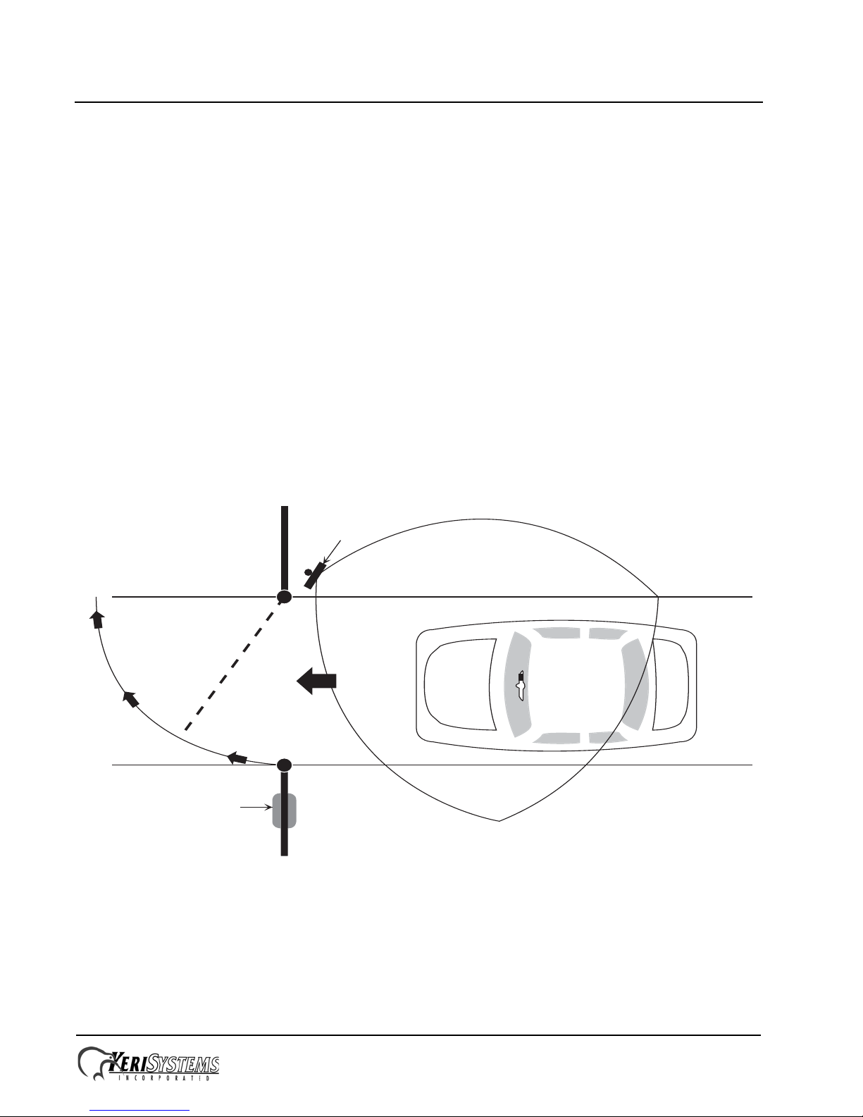
2.1 Exciter Orientation
2.1.1 Horizontal Plane
The horizontal orientation of the Exciter is set so that the center of the pattern is directed at the right edge of the road,
which permits the left half of the detection pattern to cover most of the entry lane. Refer to Figure 2.
Figure 2: The Horizontal Antenna Coverage Pattern
RXR-10
Receiver
EX-10
Exciter
LRT-5
Transponder
GATE

V-Track™ Automatic Long Range Vehicle ID System
Installation Guide
Page 3 of 20 P/N: 01538-001 Rev. G
2.1.2 Vertical Plane
Vertical orientation is adjusted so as to aim the antenna at a spot about twenty feet (6.5 M) on the road from the Exciter.
From this spot forward, the detection area will increase as you get closer to the gate. This is shown in Figure 3.
Figure 3: The Vertical Antenna Coverage Pattern
2.1.3 External Arming Input
Some installations prefer that the V-Track not be active until a vehicle approaches. The V-Track system is built with an
input for external arming. This allows the use of road loops, IR detectors, pressure sensors, etc. to activate the V-Track
system Antenna/Exciter. This system is not active until the loop input wires (brown and blue on the Exciter) are shorted
together. This can be accomplished by using the arming devices output; either an open collector or the dry contacts of a
relay.
The blue wire is the high input and the brown wire is the low (ground). If there is no external arming device used, these
two wires must be connected together and this will turn the Antenna/Exciter on and allow it to function any time a
transponder is in range.
20 Feet
EX-10
Exciter
5 to 9
Feet
Optional Speed Bump
LRT-5
Transponder

V-Track™ Automatic Long Range Vehicle ID System
Installation Guide
Page 4 of 20 P/N: 01538-001 Rev. G
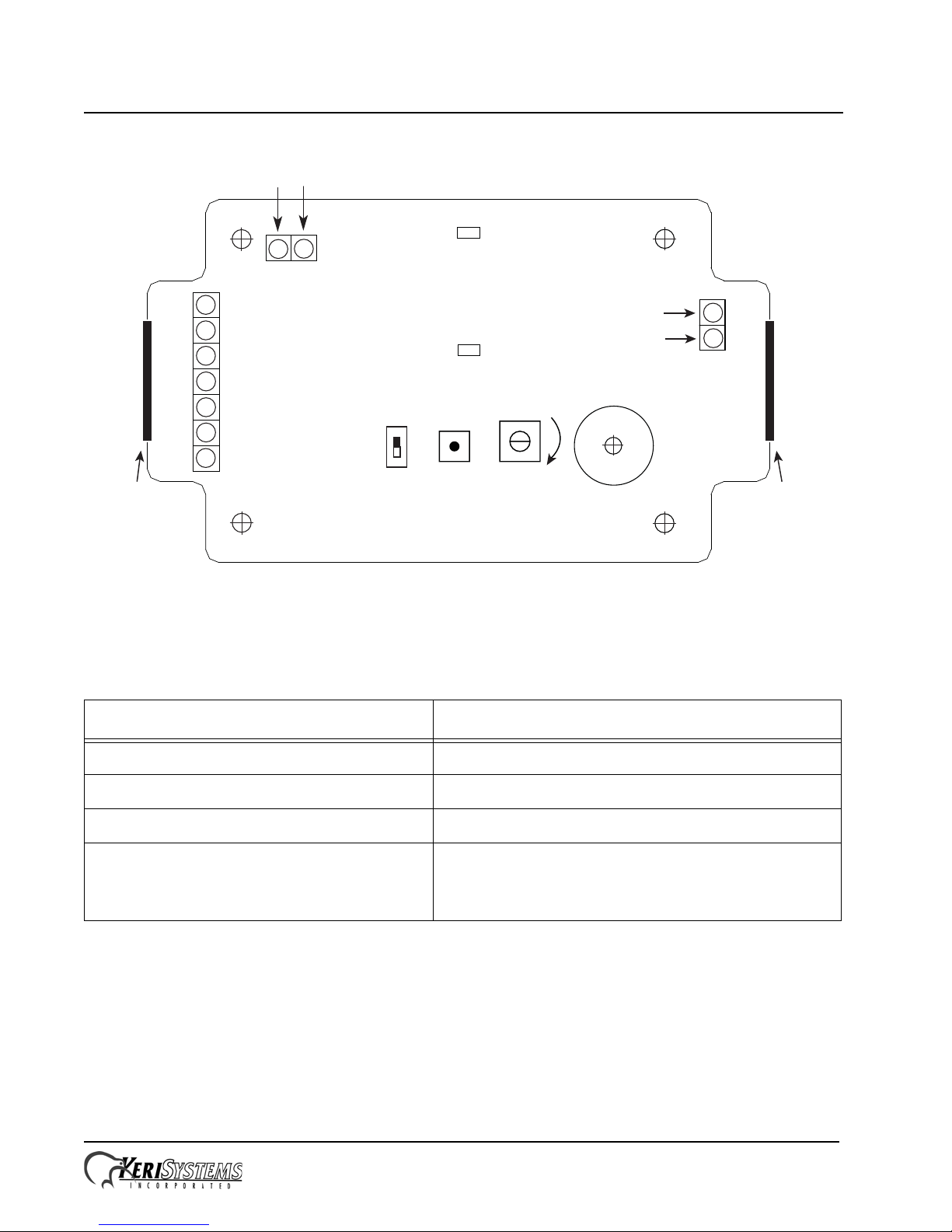
2.2 Exciter Electrical Installation
The Exciter comes configured from the factory for single-lane or for dual-lane entrance/dual-lane exit applications.
Make wiring connections as follows:
• In single-lane applications only the Power (red) and Ground/Shield (black/silver) connections are made. Clip off the
unneeded Green and White wires.
• In dual-lane applications, connect the A-wire (green) to the LRT Receiver at J3 and connect the B-wire (white) to the
LRT Receiver at J3. Then connect the Power (red) and Ground/Shield (black/silver) wires.
• If the Arming Input is not being used, the Arming Input High (blue) and Arming Input Low (brown) wires MUST be
shorted.
Please refer to Section 6.0 in this Installation Guide for more information on Enter/Exit (two-lane) applications.
Figure 4: Exciter PCB
RF Antenna Cable
SHIELD
(connect to ground)
GND - BLACK
+12 VDC - REDA-wire - GREEN (to LRT Receiver, J3)
B-wire - WHITE (to LRT Receiver, J3)
not used in
single-lane
applications
EX-10
Exciter
Exciter
conguration
label
Mounting
Hardware
Exciter
Antenna
Power/Data
Cable
Arming Input Low - BROWN (to Arming Device) Arming Input High - BLUE
(to Arming Device)

V-Track™ Automatic Long Range Vehicle ID System
Installation Guide
Page 5 of 20 P/N: 01538-001 Rev. G
Keri recommends the following cable gauges:
• AWG 18 allows up to 500 feet
• AWG 22 allows up to 200 feet
• AWG 24 allows up to 100 feet
2.3 The Exciter’s Antenna
The EX-10 Exciter’s antenna can have a gain of no more than 8.1 db, per FCC regulations. For best operation the coaxial
cable between the antenna and transmitter should be kept as short as practical. We recommend no more than 10 feet.
Longer coax lengths than this will reduce the operating range of the system.
NOTE: The cable seals in the body of the Exciter enclosure are designed to accommodate one cable. Forcing more than
one cable through these seals compromises the weather-tight seal, allowing water to enter the body of the enclosure.
Table 1: EX-10 Exciter Electrical Requirements
Parameter Requirement
Power Supply Nominal DC Voltage 12.0 VDC
Voltage Range 11.0 VDC to 15.0 VDC
Nominal Current 500 mA
Recommended Power Supply 12 VDC @ 1 A or greater
fully regulated
RF Connector Type RPSMA

V-Track™ Automatic Long Range Vehicle ID System
Installation Guide
Page 6 of 20 P/N: 01538-001 Rev. G
3.0 RXR-10 Receiver Installation
The Receiver range pattern is omnidirectional, a large, circular shape with a radius of up to 100 feet (30M). A typical
mounting location is in a gatehouse for gated communities, or other enclosure, which makes it convenient to provide a
data cable from the Receiver to the control unit. An external antenna can be installed if the Receiver is mounted in a
difficult RF signal area. The LRT-5 Transponder sends its signal to the Receiver at 433 MHz so the detection pattern is
very similar to that of a garage door opener or the remote unlock on your automobile. Cable type and run length are like
any proximity reader and are specified below. The Receiver antenna detection pattern is shown in Figure 5.
Figure 5: RXR-10 Receiver Detection Pattern – 100 Foot Radius Circle
The PC Board outline for the RXR-10 Receiver is shown in Figure 6 on page 7. The Receiver is equipped with a Range
adjustment potentiometer (RV1). For single lane applications the system installer only needs to supply DC power to the
Receiver and Exciter. For information on Enter/Exit applications, please refer to Section 6.0 in this Installation Guide.
RXR-10 Receiver
Gatehouse or similar location
Up To 100 Feet
LRT-5
Transponder
V-Track™ Automatic Long Range Vehicle ID System
Installation Guide
Page 7 of 20 P/N: 01538-001 Rev. G
Figure 6: Receiver PCB
Keri recommends the following cable gauges:
• AWG 22 allows up to 500 feet
• AWG 24 allows up to 200 feet
Wire the Receiver to the access panel per the appropriate diagram in Section 7.3.
NOTE: The cable seals in the body of the Receiver enclosure are designed to accommodate one cable. Forcing more than
one cable through these seals compromises the weather-tight seal, allowing water to enter the body of the enclosure.
Table 2: RXR-10 Receiver Electrical Requirements
Parameter Requirement
Power Supply Nominal DC Voltage 12.0 VDC
Voltage Range 11.0 VDC to 15.0 VDC
Nominal Current 100 mA
Recommended Power Supply 12 VDC @ 250 mA or greater, fully regulated,
- Receiver can be powered by the host controller’s
12 VDC supply
External
Antenna
Connector
Red LED
Green LED
Beeper
RV1
Range
Adjust
S1
Antenna
Ground
1
2
3
4
5
6
7
+12 VDC
Ground
Ground
Ch A Out/D0
Ch A/D1
Ch B Out/D0
Ch B/D1
A / Rx (Green Wire) B / Tx (White Wire)
S2
Grommet
(on enclosure
cover)
Grommet
(on enclosure
cover)
increase
V-Track™ Automatic Long Range Vehicle ID System
Installation Guide
Page 8 of 20 P/N: 01538-001 Rev. G
4.0 V-Track System Setup and Checkout
The Setup and Checkout process requires the use of an LRT-5 Transponder. The LRT-5 is equipped with an LED that
flashes Red when in the coverage area of the Exciter. The Red flashing LED indicates that it is in the Exciter field and is
shipping data to the RXR-10 Receiver.
Perform the following steps after you have installed and wired the V-Track system equipment:
1. Short together the Arming Input Low and High lines (the Brown and Blue wires) on the EX-10 Exciter.
2. Remove the cover from the RXR-10 Receiver and maximize Receiver sensitivity by rotating the range potentiometer
(RV1) fully clockwise (see Figure 6).
3. Power up the Receiver and the EX-10 Exciter.
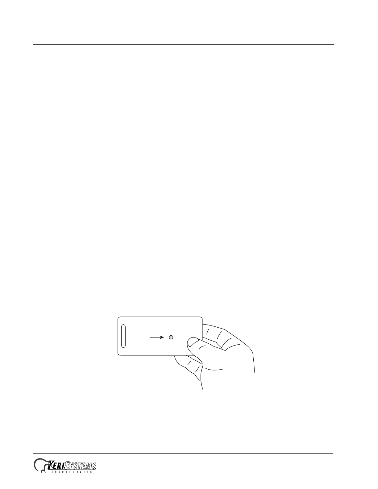
4. Hold the LRT-5 Transponder in your hand. By walking the area you can quickly determine the area of coverage.
When the Red LED is blinking, you are in a covered area. If the LED stops blinking, you are out of the covered area.
Proper orientation of the Exciter/Antenna can be quickly accomplished by using the LRT-5 as your test equipment
(see Figure 7).
5. Correspondingly, while the Transponder is in the vehicle travel lane, the Receiver’s green LED will blink off/on to
indicate the Receiver recognizes the Transponder is with in range and the Receiver’s red LED will flash off every 20
seconds to indicate the Transponder’s ID code was transmitted by the Receiver to the access control panel.
NOTE: In standard operation the Receiver sends Transponder ID data to the access control system every 20 seconds for
as long as a Transponder remains in the Exciter’s field. This feature, called Last Card Lock Out (LCLO), prevents the
Receiver from overwhelming an access control system with repeated submissions of the same Transponder ID. In standard
operation, when a new ID is received (when a new Transponder enters the vehicle travel lane), the Receiver will send the
new ID immediately and apply LCLO to the new ID.
6. If the LED functions between Transponder and Receiver are not consistant, there is a problem with signal coverage in
the vehicle travel lane. Verify the Receiver is within 100 feet of the desired coverage area (see Figure 5) and the
Exciter is properly oriented (see Figure 2 and Figure 3) to cover the vehicle travel lane.
7. If the LED functions between Transponder and Receiver are consistant, you can further verify proper operation by
presenting an LRT-5 Transponder into the vehicle travel lane and verifying the ID code being sent by the Receiver to
the access control system is correct by comparing the ID code on the Transponder to the ID code displayed by the
access control system software.
8. Remove the short between the Arming Input Low and High lines (the Brown and Blue wires) on the EX-10 Exciter.
Figure 7: TT-1 Presentation Orientation for Field Test
Red
LED

V-Track™ Automatic Long Range Vehicle ID System
Installation Guide
Page 9 of 20 P/N: 01538-001 Rev. G
4.1 Receiver Sensitivity Adjustment
For installations of a single Receiver, it is typically fine to leave the sensitivity control at maximum (the factory default
setting).
Installations that have access points 500 feet or less apart require Receiver sensitivity adjustment. Receivers are designed
to be sensitive, long range devices to offer the best possible operation. As a result, if you have access points in reasonably
close proximity the Transponder signal may be received by more than one Receiver. This results in incorrect system
operation and must not be allowed to happen.
If your site has access points in close proximity, following the System Setup and Checkout procedure Keri recommends
the following:
1. Remove the Receiver cover. There two LEDs, one Red and one Green (see Figure 6 on page 7). The Green LED
blinks off when a Transponder is in range and the Red LED blinks off when a proper code is detected and data is
shipped to the host controller.
2. Place your Transponder in the field of Access Point A. Make certain that the LED on the Transponder is blinking
indicating proper operation. Now, look at any nearby Receiver other than that of Access Point A. If its Red LED is
blinking, the sensitivity of that Receiver must be reduced by turning the control in a counter clockwise direction.
Reduce this setting until the Red LED no longer blinks, then turn an additional 1-2 degrees for a safety margin.
3. This procedure needs to be repeated at all Receivers, until all Access Points have been tested. Of course this means
that the Test Transponder will need to be placed at the antenna of each gate and all nearby Receivers checked for
proper sensitivity settings.
4. When this is completed, test to make sure the Transponder is still seen on the desired Receiver. If it is not possible to
reduce unwanted Transponder reads without degrading the desired signals, then the Receivers will need to placed
further apart.
With multiple gates, this task will take a few minutes per Access Point, but is well worth the time spent as it eliminates the
possibility of a vehicle opening an Access Point other than the one it is entering.
4.2 Transponder Enrolling
The V-Track Transponders you receive should be in consecutive ID numbers with no breaks or missing numbers. Keri
recommends enrolling these Transponders using the block enrollment feature provided by the Keri software (enrolling all
consecutively numbered Transponders into the cardholder database at one time by number range). If you are intending to
use learn enrollment (presenting Transponders to a reader one-at-a-time) please contact Keri Technical Support for
information.

V-Track™ Automatic Long Range Vehicle ID System
Installation Guide
Page 10 of 20 P/N: 01538-001 Rev. G
5.0 LRT Vehicle Installation
Figure 8 shows the optimal placement of the Transponder in order of signal response performance. Install the Transponder
using the provided double-sided tape or Velcro™ (see Figure 9 on page 10). Ensure the label-end of the Transponder is
mounted away from the rear-view mirror’s mounting post. Prior to installation, make certain the desired location complies
with all state and local vehicle code laws. Optimal placement of the Transponder is behind the rear-view mirror, out of the
driver's vision (Location 1, below).
Figure 8: Optimal Transponder Installation Locations
Figure 9: Transponder Mounting Tape
1
2
3
double-stick tape for windshield mounting
(remove and replace with Velcro
TM
strips if desired)
label recess
mount this end of Transponder
away from
rear-view mirror mounting post
rear-view
mirror
mounting post
V-Track™ Automatic Long Range Vehicle ID System
Installation Guide
Page 11 of 20 P/N: 01538-001 Rev. G
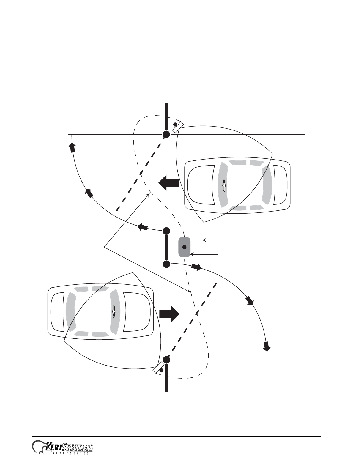
6.0 Enter-Exit Lane Installation
The Keri RXR-10 receiver has the capability of controlling two EX-10 Exciters for Enter/Exit applications (see Figure
10). The EX-10 Exciter should arrive configured for your application from the factor. Labels on the Exciter cover identify
individual units as either Single-Lane, Dual-Lane IN, or Dual-Lane OUT. Refer to Section 9.0 on page 20 should you
need to reconfigure an Exciter for a new purpose.
Figure 10: V-Track Enter-Exit Lane Application
RXR-10 Receiver
Gatehouse or similar location
EXIT
ENTER
EX-10 Exciter
EX-10 Exciter
RS-485 Connection
Shielded, Twisted Pair
V-Track™ Automatic Long Range Vehicle ID System
Installation Guide
Page 12 of 20 P/N: 01538-001 Rev. G
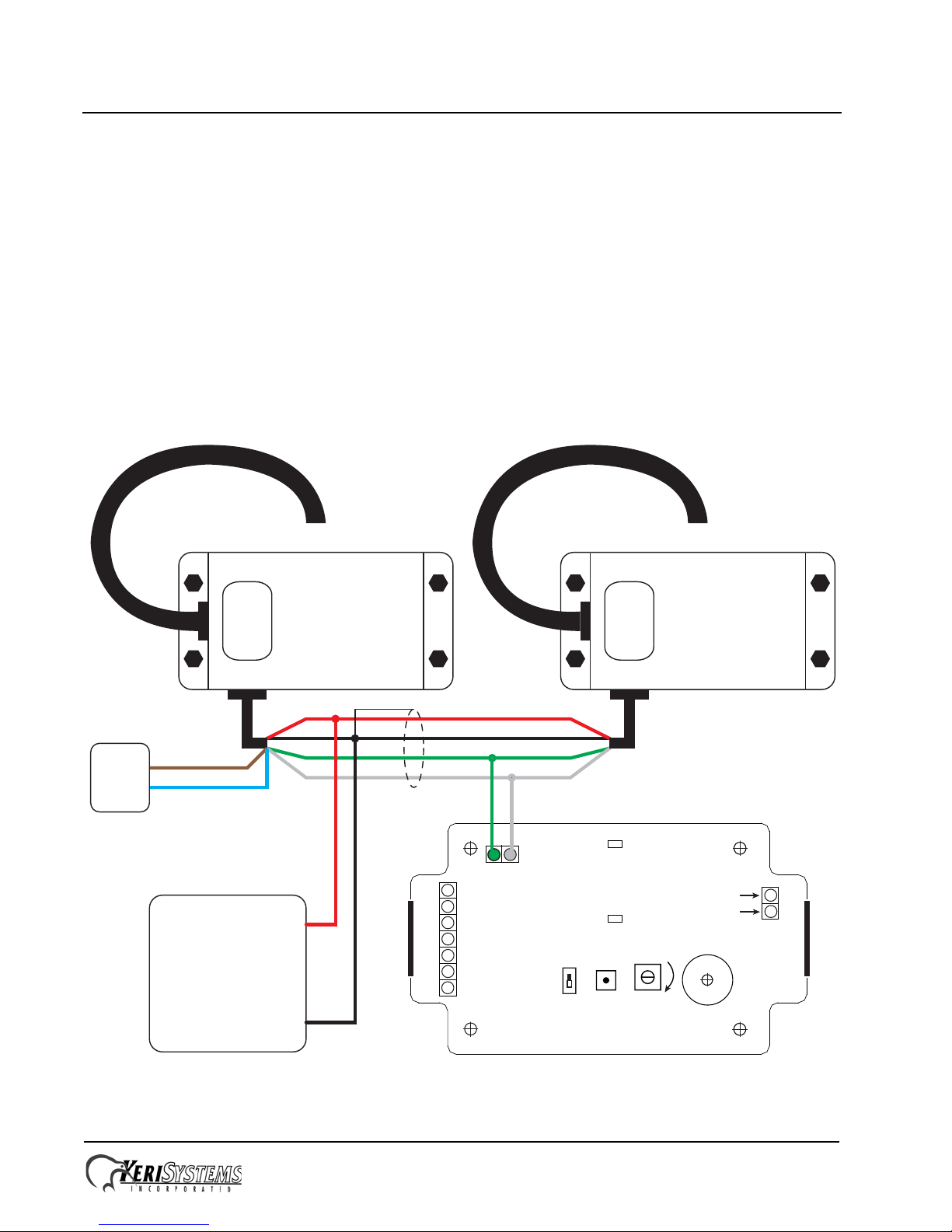
For Enter-Exit applications, the RS-485 electrical interface must be connected between the two EX-10 Exciters and the
RXR-10 Receiver (see Figure 11 for a wiring diagram). The total length of the RS485 wiring must be less than 500 feet.
NOTE: The RS485 interface is only required for two-lane operation. Do NOT connect the RS-485 wiring when in single-
lane operation.
6.0.1 System Checkout
The instructions provided in Section 4.0 apply for Enter-Exit operation; however, they need to be performed for each
vehicle travel lane independently. You may consider reducing each Receiver’s sensitivity to minimize interference
between the vehicle travel lanes.
7.0 Wiring Diagrams
7.1 Dual-Lane Exciters to Receiver
This wiring connection applies to systems in Dual-Lane In/Out applications.
Figure 11: Dual-Lane Exciters to Receiver
RXR-10 Receiver PCB
External
Antenna
Connector
Red LED
Green LED
Beeper
Range
Adjust
Channel
Select
ON
Antenna
Ground
1
2
3
4
5
6
7
+12 VDC
Ground
Ground
Ch A Out/D0
Ch A/D1
Ch B Out/D0
Ch B/D1
Reset
A/Rx B/Tx
NOTE: The RS-485 connection is
not used when using one Exciter
in a single-lane application.
EX-10
Exciter
ENTER
EX-10
Exciter
Exciter
Antenna
Connection
Exciter
Antenna
Connection
Power
Supply
+ 12 VDC
Ground
Power Lines
Red / Black
RS-485 Data Lines
White / Green
Connect Shields to Ground
EXIT
Arming
Device
RED
BLACK
GREEN
WHITE
BROWN
BLUE
NOTE: Short the Brown
and Blue lines if NO
Arming Device is used.

V-Track™ Automatic Long Range Vehicle ID System
Installation Guide
Page 13 of 20 P/N: 01538-001 Rev. G
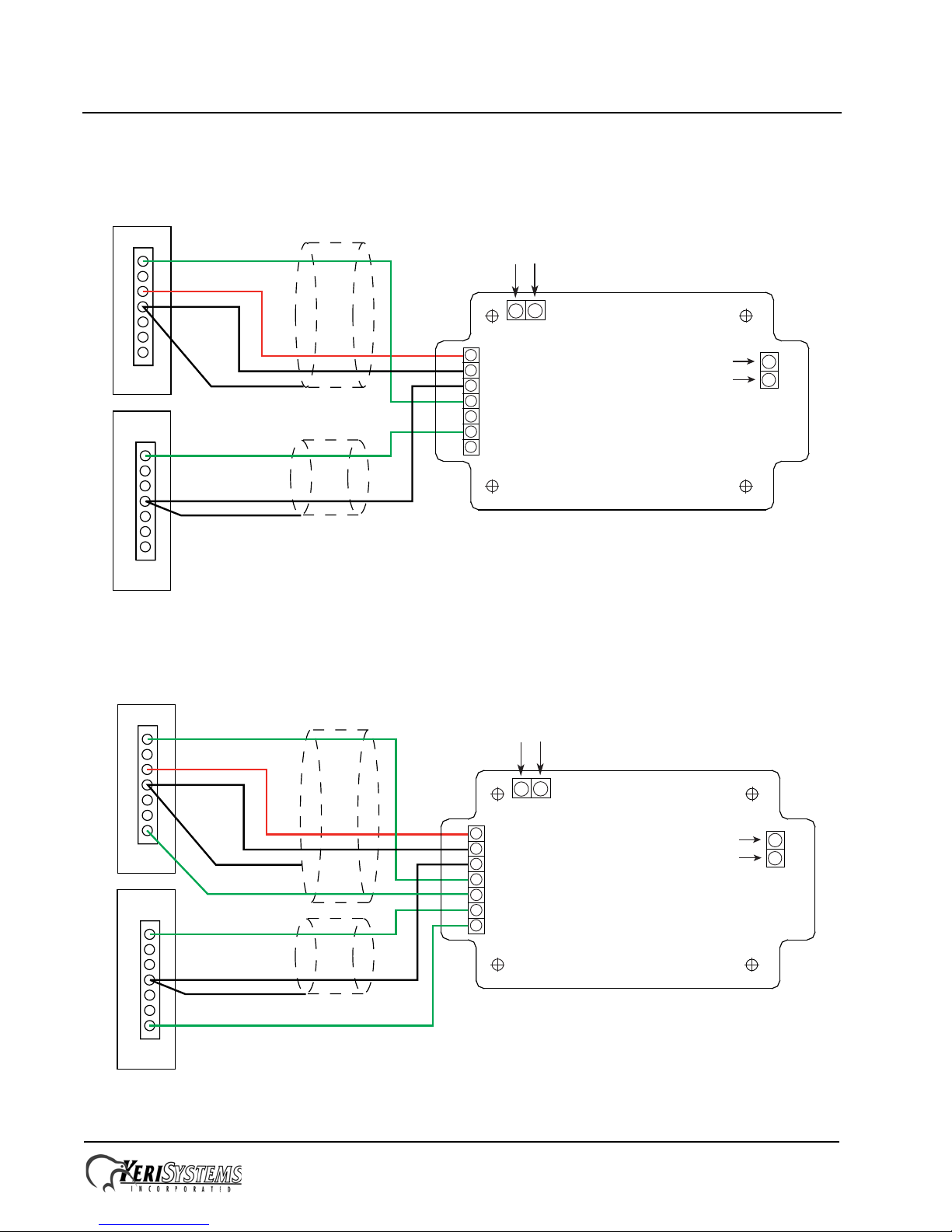
7.2 Single-Lane Exciter Connection
This wiring connection applies to systems in Single-Lane applications.
Figure 12: Single-Lane Exciter Connection
NOTE: The RS-485 connection to an Exciter is not used
in a single-lane application (the White and Green lines).
EX-10
Exciter
ENTER
Exciter
Antenna
Connection
Power
Supply
+ 12 VDC
Ground
Power Lines
Red / Black
Connect Shield
to Ground
Arming
Device
Brown
Blue
NOTE: Short the Brown and Blue
lines if NO Arming Device is used.

V-Track™ Automatic Long Range Vehicle ID System
Installation Guide
Page 14 of 20 P/N: 01538-001 Rev. G
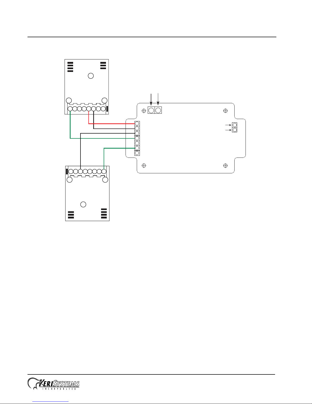
7.3 Single Lane Applications
7.3.1 For PXL-P Controllers – Keri MS-Proximity
Figure 13: Receiver to PXL-P Controller – Single Lane Application
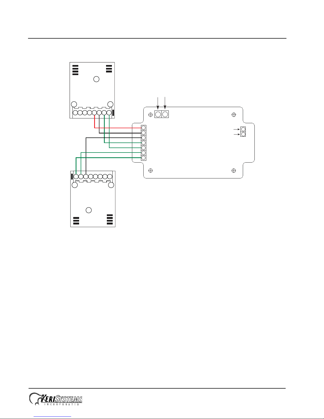
7.3.2 For PXL-W Controllers – Wiegand
Figure 14: Receiver to PXL-W Controller – Single Lane Application
Receiver
PXL-500P
Data Channel A
+12V
Drain
Ground
1
2
3
4
5
6
7
1
2
3
4
5
6
7
TB-5
TB-6
1
2
3
4
5
6
7
External
Antenna
Connector
Antenna
Ground
+12VDC
Ground
Ground
Channel AOut
N/A
Channel BOut
N/A
A/Rx B /Tx
Receiver
PXL-500W
Data Channel A
+12V
Drain
Ground
1
2
3
4
5
6
7
1
2
3
4
5
6
7
TB-5
TB-6
1
2
3
4
5
6
7
External
Antenna
Connector
Antenna
Ground
+12VDC
Ground
Ground
Channel A/D0
Channel A/D1
N/A
N/A
A/Rx B /Tx

V-Track™ Automatic Long Range Vehicle ID System
Installation Guide
Page 15 of 20 P/N: 01538-001 Rev. G
7.3.3 For NXT Controllers via RIM – Keri MS-Proximity
Figure 15: Receiver to NXT Controller via RIM – Keri MS-Proximity – Single Lane Application
7.3.4 For NXT Controllers via RIM – Wiegand
Figure 16: Receiver to NXT Controller via RIM – Wiegand – Single Lane Application
External
Antenna
Connector
Antenna
Ground
1
2
3
4
5
6
7
1 2 3 4 5 6 7 8
NXT-RIM
Receiver
+12VDC
Ground +12VDC
Ground
Ground
Channel AOut
N/A
Channel BOut
N/A
A/Rx B /Tx
External
Antenna
Connector
Antenna
Ground
1
2
3
4
5
6
7
123 4 5 6 7 8
NXT-RIM
Receiver
+12VDC
Ground
Ground
Wiegand D0
Wiegand D1
N/A
N/A
A/Rx B /Tx
V-Track™ Automatic Long Range Vehicle ID System
Installation Guide
Page 16 of 20 P/N: 01538-001 Rev. G
7.4 Enter/Exit Two Lane Applications
7.4.1 For PXL-P Controllers – Keri MS-Proximity
Figure 17: Receiver to PXL-P Controller - Enter/Exit, Two Lane Application
7.4.2 For PXL-W Controllers – Wiegand
Figure 18: Receiver to PXL-W Controller - Enter/Exit, Two Lane Application
1
2
3
4
5
6
7
1
2
3
4
5
6
7
PXL-500P
PXL-500P
Data Channel A
Data Channel B
+12VDC
Drain
Ground
Drain
Ground
TB-5/6
TB-5/6
Receiver
External
Antenna
Connector
Antenna
Ground
1
2
3
4
5
6
7
+12VDC
Ground
Ground
Channel AOut
N/A
Channel BOut
N/A
A/Rx B /Tx
1
2
3
4
5
6
7
1
2
3
4
5
6
7
PXL-500W
PXL-500W
Ch A/D0
Ch B/D0
+12VDC
Drain
Ground
Drain
Ground
TB-5/6
TB-5/6
Receiver
External
Antenna
Connector
Antenna
Ground
1
2
3
4
5
6
7
+12VDC
Ground
Ground
Channel A/D0
Channel A/D1
Channel B/D0
Channel B/D1
A/Rx B /Tx
Ch A/D1
Ch B/D1
V-Track™ Automatic Long Range Vehicle ID System
Installation Guide
Page 17 of 20 P/N: 01538-001 Rev. G
7.4.3 For NXT Controllers via RIM – Keri MS-Proximity
Figure 19: Receiver to NXT Controller via RIM – Keri MS-Proximity – Enter/Exit, Two Lane Application
External
Antenna
Connector
Antenna
Ground
1
2
3
4
5
6
7
123 4 5 6 7 8
NXT-RIM
Receiver
+12VDC
Ground
Channel
A
1
23
4
5678
NXT-RIM
+12VDC
Ground
Ground
Channel AOut
N/A
Channel BOut
N/A
Channel
B
Ground
NOTE: Connect power only to theNXT-RIM
with the“Channel A Out” connection).
A/Rx B /Tx
V-Track™ Automatic Long Range Vehicle ID System
Installation Guide
Page 18 of 20 P/N: 01538-001 Rev. G
7.4.4 For NXT Controllers via RIM – Wiegand
Figure 20: Receiver to NXT Controller via RIM – Wiegand – Enter/Exit, Two Lane Application
8.0 Troubleshooting Read Range Issues
This section will help you troubleshoot read range issues with the V-track system. You will need an LRT-5 Transponder to
perform these steps. In order to resolve these issues it helps to understand the basic operation of the V-Track system. It
consists of three parts:
• Antenna/Exciter
• Receiver
• Vehicle Tag
The antenna/exciter operates as a remote “switch” that activates the tag. Whenever the tag is in the field, it will transmit
data. This is easily proven with the use of the provided test tag. For this portion of testing, no receiver is required.
When the tag is activated it will transmit the encoded ID number via an RF signal to the receiver.
The receiver can be located up to 100 ft from the vehicle being detected. When a signal with correct data is received, the
receiver processes this and ships it to the host controller through the connecting data cable.
External
Antenna
Connector
Antenna
Ground
1
2
3
4
5
6
7
123 4 5 6 7 8
NXT-RIM
Receiver
+12VDC
Ground
Channel B
1
23
4
5678
NXT-RIM
+12VDC
Ground
Ground
Channel A/D0
Channel A/D1
Channel B/D0
Channel B/D1
Channel A
Ground
NOTE: Connect power only to theNXT-RIM
with the“Channel A Out” connection).
A/Rx B /Tx

V-Track™ Automatic Long Range Vehicle ID System
Installation Guide
Page 19 of 20 P/N: 01538-001 Rev. G
8.1 Antenna/Tag Orientation
We sometimes encounter complaints that the read range varies widely – sometimes acceptable and sometimes almost
useless. On several occasions it was determined that the antenna was installed in the vertical plane. The tags were being
presented in the horizontal plane. While this does work with somewhat reduced range, it can easily become impossible for
the installer to orient the antenna to provide the desired coverage area. Before starting we want to ensure that the antenna
and tag are both oriented in the same polarity.
Orient the antenna in the horizontal plane. This is when the white coaxial cable exits the square antenna on the side. If it
exits top or bottom it is polarized in a vertical mode. The tag is also horizontally polarized when held in the horizontal
position.
Ignore the receiver and controller for now, our first concern is with the Exciter/Antenna and LRT-5 tag.
USE THE TAG! As explained in the installation instructions, you orient the antenna in the approximate direction of
required coverage. Then you take the test tag and walk the area while watching for the LED blinking. So long as the LED
is blinking you are in the “read” area. When the LED stops, you are outside the area. It may be necessary to adjust the
antenna orientation a few times until you have the desired area of coverage.
NOTE: If the receiver output is used for this purpose, there is a 20 second delay between responses. This delay makes is
almost impossible to rely on the receiver for orientation and testing purposes. This is why we recommend that you forget
about the receiver until later in the testing process. This delay is a lockout function to prevent multiple reads from the
same vehicle from unnecessarily filling the data base. If the vehicle has to wait a few seconds for the gate to open you
would see many reads without the last card lockout. It is explained in more detail in the Installation Guide.
8.2 Using the Receiver as a Tester
When you are comfortable that you have the optimum area of coverage for this job, it is time to move on to the receiver.
Place the test tag in an area where it is being activated by the exciter. Remove the cover from the receiver housing. You
will see that the receiver is mounted on the cover. There is a red LED and a green LED. These are both illuminated
constantly when the power is applied. They will blink off under the following conditions:
• Green LED blinks off when a signal from a tag is received.
• The Red LED will blink off when the receiver receives this signal and determines that it is a valid V-Track code.
When the Red LED blinks off, the encoded data has been shipped to the receiver output port and will be transmitted
over the connecting cable to the host controller.
• With the tag in the field the Green LED should blink quite often. The Red LED should blink every 25 seconds.
Each time the Red LED blinks, you should see the response at the controller. If there is no data received at the controller,
you have an installation related problem, such as:
• Bad cable connection
• Data lines reversed
• Wrong wiring of data cable, crossed wires, etc
• Wrong type data output, Wiegand as opposed to Keri MS reader format
• Data cable connected to the wrong receiver output port
- Channel A output is for single lane systems
- Dual lane systems will transmit on both A and B outputs, corresponding to the lane in which it the tag was located
Once you are sure that the data is being received and seen at the controller, place a tag in the desired location of a vehicle.
A quick test should show that it also works in the vehicle.
You should now have a working V-Track system.

V-Track™ Automatic Long Range Vehicle ID System
Installation Guide
Page 20 of 20 P/N: 01538-001 Rev. G
8.3 Points to Remember
The “Range” control on the receiver has absolutely no impact on the antenna power or its coverage area. This is a receiver
sensitivity control that allows the receive range to be reduced to eliminate unwanted signals from other V-Track systems
in the same general area. It only affects the usable distance between the vehicle tag and the receiver. It is recommended to
set it at maximum if there are no other systems in the vicinity.
If it is necessary to mount the receiver in a housing, we recommend using a non-metallic box. Radio frequencies (RF) will
not travel through metal. If it is necessary to use a metal housing, then an external antenna must be attached to the
receiver.
9.0 Contact Keri Systems
end of document
Keri USA Keri UK, Ireland, Europe
2305 Bering Drive
San Jose, CA 95131 Unit 17
Park Farm Industrial Estate
Ermine Street
Buntingford
Herts SG9 9AZ UK
Telephone: (800) 260-5265
(408) 435-8400 Telephone: + + 44 (0) 1763 273 243
Fax: (408) 577-1792 Fax:+ 44 (0) 1763 274 106
Web: www.kerisys.com Web:www.kerisystems.co.uk
E-mail: [email protected]
Table of contents
Popular Automobile Accessories manuals by other brands

Kuda-Phonebase
Kuda-Phonebase 056000 Installation instruction

Glacier
Glacier Air-Boss 67 Intake Plenum installation instructions

Whispbar
Whispbar K561W Fitting instructions

Kuda
Kuda 191470 Installation instruction

Charge Amps
Charge Amps Halo Pole Mount manual

Steinhof
Steinhof S-398 FITTING AND OPERATION MANUAL

Bedrug
Bedrug Bedliner installation instructions

Dakota Digital
Dakota Digital REM-1C manual

OHC Motors
OHC Motors Intelligence Instruction book

Blaupunkt
Blaupunkt AVMC 1.0 Operating and installation instructions

Quadratec
Quadratec QuadraTop Adventure Top 1113.00 Series installation manual

Kuda-Phonebase
Kuda-Phonebase 276100 Installation instruction


