Kessel UNIVA-Aqualift User manual

DEINBAU- UND BEDIENUNGSANLEITUNG
GB
INSTALLATION AND OPERATING INSTRUCTIONS
F
INSTRUCTIONS DE ONTAGE ET DE SERVICE
KESSEL - Aqualift Hebeanlage
bis Baujahr 12/95
DDie komplette Schmut wasserhebeanlage
mit Rückschlagklappe
GB Complete Wastewater lifting
System with backflow Preventer
FPoste complet de relevage
des eaux usées avec clapet antiretour
Produktvorteile
Name/Unterschrift Datum Ort Stempel Fachbetrieb
Installation
der Anlage urde durchgeführt von Ihrem Fachbetrieb:
Inbetriebnahme Ein eisung
Änderungsstand: 11/2009- G
Sachnummer: 099-143
Techn. Änderungen vorbehalten

2
Inhaltsverzeichnis
Allgemeines
.......................................................................................................... Seite 3/4
Einbau / Installation / Installation
.......................................................................................................... Seite 5-9
Einbaubeispiele / Examples of installation
odele d’installation
.......................................................................................................... Seite 10
Einbaumuster / odel of installation
odèle d’installation
.......................................................................................................... Seite 11
Einbautips / odels of installation
odèles d’installation
.......................................................................................................... Seite 12/13
Technische Daten / Technical data
Donnèes techniques
.......................................................................................................... Seite 14
Leistungstabelle / Table of performance
Tableau de rendement
.......................................................................................................... Seite 15
Abmessungen (Pumpe) / Dimensions (Pump)
Dimensions (Pompe)
.......................................................................................................... Seite 15
Achtung! / Attention! / Attention!
.......................................................................................................... Seite 16
Gewährleistung / Warranty / Garantie
.......................................................................................................... Seite 17-19

Allgemeines
D
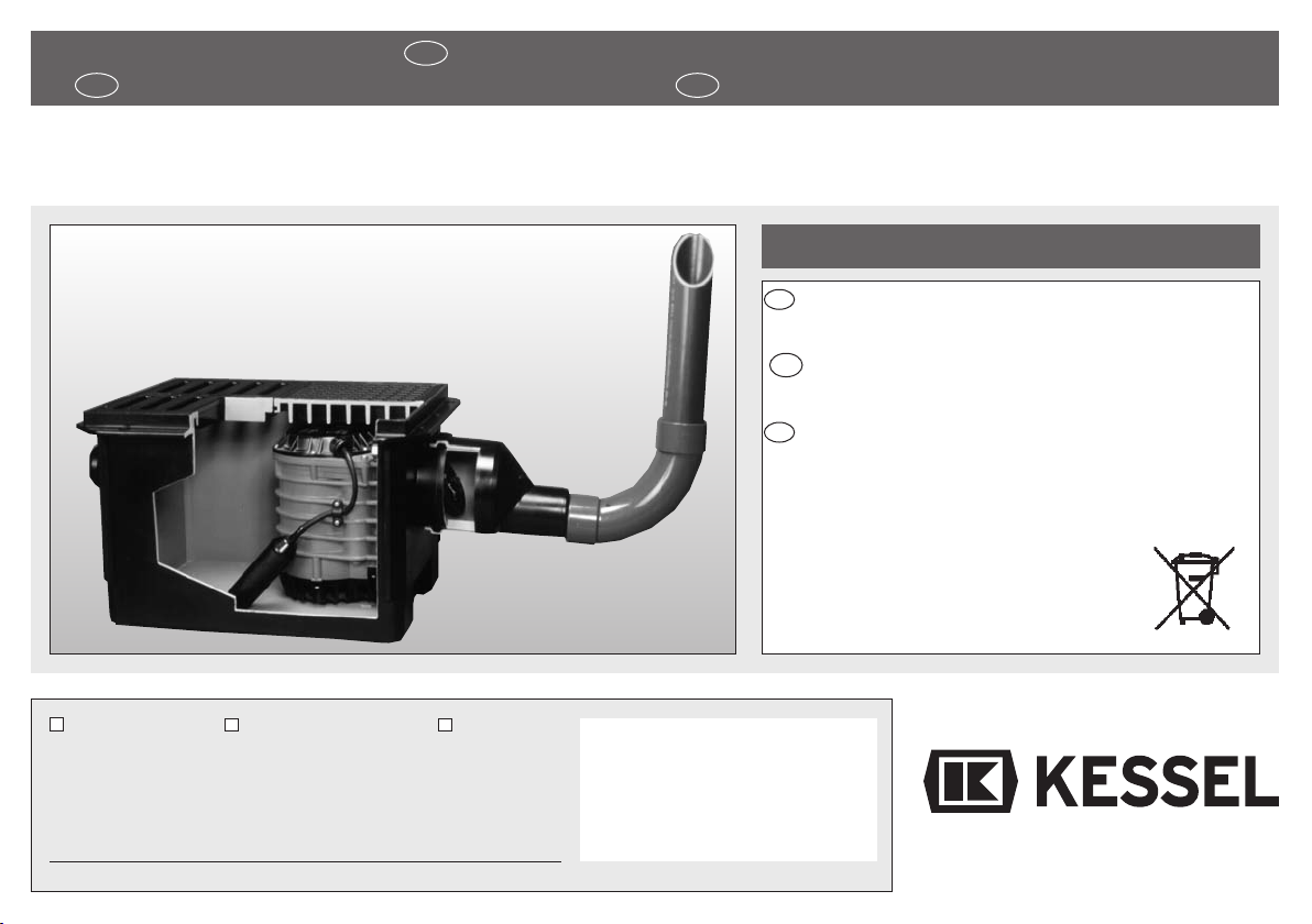
Die komplette Schmutzwasserhebe-
anlage mit Rückschlagklappe
Durch den Einsatz von dauerresistenten,
hochwertigen und hochschlagfesten Kunst-
stoffen haben wir eine Schmutzwasserhe-
beanlage geschaffen, die in ihrer Leistung
zum benötigten Platzaufwand unübertrof-
fen ist. Die hierzu verwendeten Stähle sind
absolut korrosionsfrei, die Kunststoffe sind
gegen haushaltsübliche Laugen und Säu-
ren beständig, ebenso gegen Kälte und
eißwasser (bis 95° C). Leistungstabelle
der Pumpe beachten (siehe letzte Seite).
Als weitere Punkte neben dem geringen
Gewicht sind die äußerst niedrige Ein-
bauhöhe und die einfache Montage der
UNIVA-Aqualift- ebeanlage zu nennen.
Der UNIVA-Aqualift ermöglicht durch wahl-
weisesAnbringen von Zulaufstutzen DN 50-
70 oder 100 den Anschluß von Ferneinläu-
fen und gewährleistet somit die sichere Ent-
sorgung von Duschen, Waschmaschinen
usw., sowie von Regenwasser aus tiefgele-
genen Räumen oder Kellerabgängen. Au-
ßerdem ist der Anschluß für Gebäude- und
Grundstücksentwässerung über Drainage-
rohr-Zuleitungen möglich. Bei Verwendung
von Aufsatzstücken kann ein stufenlos ver-
tiefter Einbau erreicht werden. Grundkörper
und Aufsatzstücke sind dicht miteinander
zu verbinden (z. B. mit Silikon, oder Tangit).
GB
Complete Wastewater lifting
System with backflow Preventer
By the use of very persistent and impact re-
sistant plastics of high-quality (slight by re-
sistant to alkaline and acid solutions, to cold
and hot water up to 95° C) as well as stain-
less steels, we have created a wastewater
lifting system which is unexcelled in its per-
formance and does not require much space.
As other advantages, we must hold up light-
ness, as well as the low height of installation
and the easy setting of the wastewater lifting
system UNIVA-Aqualift. Through the possi-
bility of adapting inlet nozzles Ø 50, 70, 100,
the UNIVA-Aqualift system enables the
branch of arriving water mains thus guaran-
teeing the disposal of water coming from
showers, washing maschines etc., as well
as rainwater from underground rooms or
outdoor basement stairs. Besides the
branch for a house-drainage system can be
connected by supply drainage pipes.
Through employment of frames (size 3, ref.
32 500), you can obtain a deeper setting, as
well as a larger capacity of the system, at all
the same time the frames enable an instal-
lation at a frost free level.
F
Poste complet de relevage des eaux
usées avec clapet antiretour
Grâce à des matières plastiques très perfor-
mantes (résistant facilement aux éléments
caustiques et aux acides, résistant égale-
ment aux variations de température jusquʼà
95° C) et avec très haute résistance aux
3

Allgemeines
chocs, grâce aussi aux aciers inoxydables,
nous avons créé un poste de relevage des
eaux usées qui par son faible encombre-
ment ne coûte rien point de vue place.
En tant quʼautres points avantageux, il faut
citer la légèreté, ainsi que la faible hauteur
dʼinstallation intérieure et la facilité de mon-
tage du poste de relevage UNIVA-Aqualift.
Grâce à la possibilité dʼadapter des rac-
cords dʼalimentation Ø 50, 70, 100, le poste
UNIVA-Aqualift perment le branchement de
conduits dʼarrivée et facilité ainsi Iʼévacua-
tion de Iʼeau des douches, machines à laver
etc., ainsi que des eaux pluviales depuis les
pièces de sous-sol ou sorties de cave. De
plus, le branchement pour Iʼextraction de
Iʼeau des bâtiments et terrains est possible
sur uns amenée de tuyau de drainage. En
utilisant des rehausses (standard 3 réf.
32500) on peut atteindre un approfondisse-
ment de Iʼinstallation ainsi quʼune plus gran-
de capacité du poste; en même temps, ces
rehausses permettent une installation à un
niveau épargné par le gel.
4

Einbau · Installation · Installation
햲햴
햳
Einhängeflansch der Pumpe
und des Gehäuses
Suspension flange of the pump
and housing
Bride de suspension de la pompe
du boîtier
Hebeanlage von oben, ohne Gitterrost und Abdeckplatte dargestellt.
Lifting unit shown from above without grate and locking cover plate.
Poste de relevage vu de haut présenté sans grille et sans couvercle.
5 eter mit Schukostecker für Anschluß
an Steckdose 230 V ~ 50 Hz. Absicherung mind. 6 Amp. träge
Wire of 5 m with plug. Power 230 V ~ 50 z.
Protection of min. 6 Amp. inert
Câble de 5 m avec prise de courant pour branchement
au secteur 230 V ~ 50 z.
Protection au moins de 6 Amp. inerte
Um Schmutzablagerungen zu vermeiden,
sollte beim Einbau des Reduzierstückes darauf geachtet werden,
daß die gerade Fläche unten liegt.
To avoid deposits of dirt, pay attention, by setting the reducer,
that it is situated on the flat part.
Afin dʼéviter les dépôts de saletés, il faut faire attention,
en montant la pièce de réduction, que celle-ci repose sur al partie plate.
Stufenlose Einbautiefe durch
beliebiges Absägen der UNIVA-
Aufsatzstücke (Best.-Nr. 32500)
Perfect equalizing by sawing the UNIVA-
frames off (ref. 32500)
Mise à niveau parfaite par découpage des
rehausses UNIVA (réf. 32500)
5

D
1. Vor dem Einbau der UNIVA-Aqualift-
Hebeanlage sind alle Teile auf äußere
Transportschäden zu überprüfen.
2. Reduzierstück (2) auf gewünschten
Druckleitungsanschluß DN 50 oder DN 40
absägen. Reduzierstück auf Ablaufstutzen
kleben (PVC-Kleber). Druckleitung (DIN
8063) anschließen (Verbindung muß Iängs-
kraftschlüssig erfolgen).
3. Kabelaustritt (7) am Gehäuse (1) oder
Aufsatzstück Best.-Nr. 32500 wahlweise
nach »Roter Montageanleitung für Zu- und
Ablaufstutzen« anbringen und beigefügten
Zulaufstutzen (7) DN 50 einschrauben
(siehe Bild 3). Ferneinläufe von Duschen,
Waschmaschinen oder Kellerabläufen fest-
legen und wahlweise Zulaufstutzen (13)
rechts, links oder mittig DN 50-70 oder 100,
anbringen.
4. Gehäuse (1) nach Anschluß sämtlicher
Rohrleitungen im Betonbett eingießen.
Zum evtl. Ausgleich des Kellerbodens ist
ein Aufsatzstück Best.-Nr. 32500 zu ver-
wenden, durch beliebiges Absägen des
Aufsatzstückes kann jede Einbautiefe
stufenlos erreicht werden.
Grundkörper
und Aufsatzstücke sind dicht miteinander
zu verbinden (z.B. mit Silikon oder Tangit).
5. Aus- und Einbau der Pumpe:
a) Ausbau:
Durch Lösen der beiden Sechskantmuttern
(10) kann die Pumpe (4) komplett mit Rück-
schlagklappe (8) und Rollring (3) aus dem
Gehäuse (1) genommen werden. Dadurch
ist ein ungehinderter Zugang zum Reinigen
der Druckleitung möglich. Durch Abziehen
der kompletten Rückschlaghalterung (8)
können Pumpe und Klappe leicht gereinigt
werden.
b) Einbau:
Vor Einbau sämtliche Dichtflächen reinigen,
Rollring (3) (bei Bedarf neuen Rollring DN
100) in die dafür vorgesehene Ringnut der
Pumpe (4) einlegen. Rückschlaghalterung
(8) fest auf Pumpenflansch aufdrücken.
Komplette Pumpe auf die zwei Schrauben
(9) im Gehäuse (1) aufstecken, an die Ge-
häusewand schieben und nach unten in den
Einhängeflansch (14) einrasten lassen. Ein
leichtes Schrägstellen der Pumpe erleich-
tert das Einrasten in den Einhängeflansch
(14). Anschließend mit den beiden Sechs-
kantmuttern (10) Pumpe und Gehäuse ver-
schrauben. Kabel mit Stecker (6) durch Ka-
belrohr (siehe Bild 3) mittels eines Zug-
drahtes einziehen und an Steckdose an-
schließen. Behälter mit Wasser auffüllen
und Schwimmerschalter (5) auf Funktion
überprüfen. Abdeckplatte (12) und Gitter-
rost (11) einlegen; es ist darauf zu achten,
daß die Abdeckplatte (12) über der Pumpe
liegt.
Besondere Bestimmungen des Instituts
für Bautechnik, Berlin:
Die Kellerentwässerungspumpen dürfen
zum eben von leicht verschmutztem Ab-
wasser nicht jedoch von solchen aus Klo-
sett- und Urinanlagen, in der Grundstücks-
entwässerung gemäß den Bestimmungen
der Norm DIN 1986 verwendet werden.
Die Druckrohrleitungen müssen über die
Einbau · Installation · Installation
6

Einbau · Installation · Installation
örtlich festgelegten Rückstauebenen hoch-
geführt werden. Der Anschluß an den
Druckstutzen muß Iängskraftschlüssig er-
folgen.
Bei Anlagen, die innerhalb von Gebäuden
verwendet werden, sind die Bestimmungen
der Norm DIN 4109 - Schallschutz im och-
bau - zu beachten.
Wartung:
Die Pumpe mindestens zweimal jährlich
äußerlich reinigen und die Einlauföffnungen
säubern, bzw. mit klarem Wasser durch-
spülen. Die Pumpe niemals selber öffnen
(nur durch Fachmann), da bei unsach-
gemäßem Eingriff die Abdichtung der Pum-
pe beschädigt werden und Öl in das Ab-
wasser gelangen könnte.
Entsprechend den Vorschriften für abwas-
sertechnische Anlagen dürfen mit der
UNIVA-Aqualift- ebeanlage keine Fäkalien
und keine brennbaren oder explosiven
FIüssigkeiten gefördert werden.
Vorsicht:
Benutzung in Schwimmbecken
und Gartenteichen und deren Schutzbe-
reich nur zulässig, wenn diese nach VDE
0100 § 49d errichtet sind. Bitte fragen Sie
Ihren Elektrofachmann.
GB
1. Before installation of the wastewater
lifting system UNIVA-Aqualift, please
check up the pieces with regard to ex-
ternal transport damages.
2. Reducer(2) to be sawn off at DN 50 or 40
according to the reguired branch of pressu-
re main. Place sealing ring (3) DN 100 into
the slot, grease and fit to the branch piece
of the housing. Pay attention that it is situa-
ted on the flat part (see drawing 1). If it is
sticked together with PVC glue, no sealing
ring (3) is needed.
3. Fix the outlet nozzle (7) of the wire to the
housing (1) or the frame ref. 32500 accor-
ding to the „red instructions for installation of
the inlet of outlet nozzle“ and screw in the
inlet nozzle (7) DN 50 (drawing 3). Fix the
arriving mains of showers, washing machi-
nes or basement sewers and connect inlet
nozzles (13) on the right, on the left or in the
middle DN 50, 70 or 100.
4. After branch of all pipes, place housing
(1) into a concrete bed.
In order to achie-
ve continuous adjustment to floor level,
use frames ref. 32500; to have a perfect
equalisation saw the frames off.
A seal of
Terroson inserted between the housing and
the frame enables, if requested a watertight
closure.
5. Removal and setting of the pump:
a) Removal:
By unscrewing both hexagon bolts (10), the
pump (4) can be completely taken off from
the housing (1) with backflow preventer (8)
and joint ring (3). By this it is possible to
clean the pressure pipe. Taking off the com-
plete backflow preventer unit, the pump and
the preventer can be easily cleaned.
b) Setting:
Before setting clean all joint surfaces, insert
sealing ring (3) (if necessary new joint DN
100) into the slot of the pump (4), fit the
7

Einbau · Installation · Installation
backflow preventer unit (8) into the flange of
the pump. Fix the complete pump in the
housing (1) with both screws (9), insert
along the inside surface of housing and
place on the suspension flange (14).Aslight
tilt of the pump facilitates its installation into
the suspension flange (14). At last, fix the
pump to the housing with both hexagon
bolts (10). Insert the electrical cable and the
plug through the blank pipe (drawing 3) with
a wire and branch into the stocket. Fill up the
housing with water and test the automatic
float (5). Put on the locking cover plate (12)
and the grate (11); it is important that the
cover plate is situated over the pump.
Particular prescriptions of the Institut
for Technical Setting, Berlin:
Basement sewers can be used in a house-
drainage system to lift wastewater which is
not very dirty, however, not coming from sa-
nitary installation (WC), according to the
prescriptions of the effluent standard DIN
1986.
Pressure pipes must always be lead over
local backwater level. The link to the pres-
sure pipe must be made with an elbow of
45°. For installation in buildings, refer to the
effluent standard DIN 4109 - protection
against noise in surface engineering.
aintenance:
Clean the pump and wash the infall ope-
nings with clear water at least twice a year.
Never open the pump by yourself (only by
an expert), because in the event of wrong
handling, the sealing of the pump can be da-
maged and oil could get into the wastewa-
ter. According to the prescriptions for instal-
lation of drainage systems, no fecal sub-
stances and no inflammable or explosive li-
quids must be extracted by the wastewater
lifting system UNIVA-Aqualift.
Attention:
To be used for swimming-pool
and garden ponds as well as the protected
area around them, only if they are establi-
shed according to VDE 0100 § 49d. Contact
your electrician.
F
1. Avant d’installer le poste de relevage
UNIVA-Aqualift, contrôler que les pièces
n’ont été endommagées par le transport.
2. Réduction (2) à scier selon le branche-
ment du tuyau pression souhaité. Placer le
joint (3) dans la rainure, graisser et em-
boîtier à Iʼouverture du boîtier. Lors de cette
opération, bien observer que la partie plate
est en bas (voir schéma 1). En collant avec
de la colle PVC, le joint (3) peut être sup-
primé.
3. Apporter la sortie de câble (7) au boîtier
(1) ou à la rehausse réf. 32500 selon „les in-
structions de montage en rouge pour le rac-
cord dʼentrée ou de sortie“ et visser le rac-
cord dʼalimentation (7) DN 50 (voir schéma
3). Fixer les conduites dʼarrivée des dou-
ches, machines à laver ou sortie de cave et
les amener aux raccords (13) de droite, de
gauche ou du milieu DN 50, 70 ou 100.
4. Après branchement de Iʼensemble de la
tuyauterie, placer le boîtier (1) dans un
moule de béton.
Pour une éventuelle mise
8

à niveau au sol de la cave, utiliser une re-
hausse réf. 32500; le découpage de la
rehausse perment une mise à niveau
parfaite.
Un joint en Terroson placé entre le
boîtier et la rehausse perment, si cela est
souhaité, un assemblage étanche.
5. Démontage et montage de la pompe:
a) Démontage:
En desserrant les deux écrous (10) on peut
sortir complètement la pompe (4) du boîtier
avec clapet anti-retour (8) et joint (3). De
cette façon, il est alors possible de nettoyer
le tuyau pression. En retirant le système
complet anti-retour, on peut ainsi nettoyer la
pompe et le clapet.
b) Montage:
Avant le montage, nettoyer Iʼensemble des
surfaces de jonction, placer le joint (3) (si
besoin nouveau joint DN 100) dans la rainu-
re de la pompe (4), emboîter le système
anti-retour (8) sur la bride de la pompe.
Fixer la pompe complette dans le boîter (1)
avec les deux vis (9), glisser vers le bas le
long de la paroi du boîtier et laisser reposer
sur la bride suspension (14). Une Iégère in-
clinaison de la pompe facilite la fixation
dans la bride de suspension. Enfin, fixer la
pompe au boîtier avec les deux écours (10).
Glisser le câble et la prise de courant (6)
dans la gaine (voir schéma 3) à Iʼaide dʼun
fil de fer et brancher au secteur. Remplir le
boîtier dʼeau et tester le flotteur automatique
(5). Placer le couvercle (12) et la grille (11);
il est important que le couvercle (12) se
situe au-dessus de la pompe.
Prescriptions particulières de I’lnstitut
de ontages Techniques, Berlin:
Les pompes vide-cave peuvent être uti-
lisées dans le drainage domestique pour le
relevage des eaux peu sales et non des
eaux provenant des installations sanitaires
(WC), selon les prescriptions de la norme
DIN 1986. Les tuyaux de pression doivent
être conduits en permanence au-dessus du
niveau des remous. Le branchement au
raccord de pression doit arriver en angle de
45°.
Pour les installations dans les bâtiments, il
faut seréférer aux prescriptions de la norme
DIN 4109 - protection contre le bruit dans
les constructions en surface.
Entretien:
Nettoyer la pompe extérieurement au moins
deux fois par an et laver les ouvertures dʼar-
rivée à Iʼeau claire. Ne jamais ouvrir la
pompe soi-même (seul un spécialiste peut
le faire), car en cas de mauvaise manipula-
tion, Iʼétanchéité de la pompe peut être
détériorée et de Iʼhuile pourrait arriver dans
les eaux usées.
Selon les inducations pour les installations
dʼévacuations dʼeau, aucune vidange et
aucun liquide inflammable ou explosif ne
doivent être extraits par le poste de releva-
ge UNIVA-Aqualift.
Attention:
Lʼutilisation dans les piscines et
réserves de jardin et dans leur zone de pro-
tection nʼest permise que si celles-ci sont
aménagées selon VDE 0100 § 49d. Rens-
eignez-vous auprès de votre électricien
agréé.
Einbau · Installation · Installation
9

Einbaubeispiele · Examples of installation · odele d’installation
Rohrverlegung für Kabel, Kabellänge: 5 m, Steckdose: 230 V ~ 50 Hz
Insertion of the cable through blank pipes length of cable: 5 m, power: 230 V ~ 50 z
Passage du câble sous gaine longueur du câble: 5 m, moteur: 230 V ~ 50 z
Kabelanschluß mit Zulaufstutzen DN 50 Nr. 39005
Connection with inlet nozzle DN 50 ref. 39005
Passage avec racord DN 50 réf. 39005
HT-Rohr
T-blank pipe
gaine T
Panzerrohr
Kabelanschluß mit NH-Ver-
schraubung und Gegenmutter
Innen Ø 48,7 mm
Typ 48
Stiffblank pipe connection with
N screwed and lock nuted link
Ø inside 48.7 mm
type 48
Gaine rigide passage avec
fermeture à vis et contre-écrou
N
Ø int. 48,7 mm
type 48
Wellrohr
Kabelanschluß mit BI O-Ver-
schraubung und Gegenmutter
Innen Ø 47,7 mm
Typ 48
Semistift blank-pipe connection
with BIMO screwed and lock
nuted link Ø inside 47.7 mm
type 48
Gaine semi-rigide
passage avec fermeture
à vis et contre-écrou
BIMO Ø int. 47,7 mm
type 48
D
Beispiel einer UNIVA-Aqualift- ebeanlage mit
Aufsatzstück Größe 3. Einbaumöglichkeiten
zur Installation des Elektrokabels und Schu-
kostecker mit verschiedenen Kabelrohren.
GB
Lifting system UNIVA-Aqualift with frame
size 3. Possibility to insert the cable and the
plug through different blank pipes.
F
Exemple de poste de relevage UNIVA-
Aqualift avec rehausse standard 3.
Possibilité dʼutiliser des gaines différentes
pour le passage du cable et de la prise.
Ferneinläufe ins Gehäuse oder Aufsatzstück DN 100 - 70 oder 50
rechts, links oder mittig möglich.
Infall pipes into the housing or into the frame DN 100, 70 or 50
possible on the right, on the left or in the middle.
Conduits dʼarrivée dans le boîtier ou la rehausse
DN 100, 70 ou 50 possible à droite, gauche ou au millieu.
Achtung für 87° HT-Bogen
müssen 2 x 45° HT-Bogen
eingesetzt werden.
Important: use two bends of
45° instead of one bend of 87°.
Attention: utiliser deux coudes
de 45° au lieu dʼun de 87°.
an
on
ouvert
aus
off
fermé
10

Einbaumuster · odel of installation · odèle d’installation
D
Einbau- und Anschlußmöglichkeiten an
UNIVA-Aqualift- ebeanlage mit höhenver-
stellbarem Aufsatzstück.
GB
Possibilities of installation and branch to the
pump UNIVA-Aqualift with adjustable frame.
F
Possibilité dʼinstallation et de branchement
à la pompe UNIVA-Aqualift avec adaptation
en hauteur des rehausses.
11

Einbautips · odels of installation · odèles d’installation
D
햲Ein leichtes Schrägstellen der Pumpe
bzw. des Notverschlusses erleichtert das
Einrasten in den Einhängeflansch (G). Beim
Einbau des Kellerablaufes ist darauf zu ach-
ten, daß die Wand im Bereich der schwar-
zen Pfeile nicht verzogen wird.
햳Der Zulaufstutzen bietet die Möglichkeit,
die ebeanlage oder das Aufsatzstück
nachträglich in jeder Richtung aufzubohren,
um Ferneinläufe zuzuführen.
GB
햲A slight tilt of the pump or of the security
lever makes easier the installation into the
suspension flange (G). By installing the ba-
sement outlet, it is important not to bend the
wall in the area shown by the black pointer.
햳The inlet nozzle offers the possibility of
boring later in all directions through the lif-
ting unit or the frames in order the lead arri-
ving mains.
F
햲
Une Iégère inclinaison de la pompe ou de
la fermeture de sécurité facilite Iʼinstallation
dans la bride de suspension (G). En montant
le système dʼevacuation de sous-sol, il est
important de faire attention à ne pas coucher
la paroi montrée par la flèche hove-joint.
햳
Le raccord dʼalimentation offre la possibilité
de percer ultérieurement dans toutes les di-
rections le poste de relevage ou les rehausses
afin dʼamener des conduites dʼarrivée.
햲햳햴
12

Einbautips · odels of installation · odèles d’installation
Gehäusedeckel
Cover plate of the housing
Couvercle du boîtier
Dichtring DN 100
Sealing ring DN 100
Joint DN 100
Klappenhalterung mit
Rückschlagklappe
Backflow preventer and support
Clapet anti-retour et support
Kondensator
Condenser
Condensateur
Ansaugkorb
Suction basket
Panier dʼaspiration
5 m-Anschlußklappe
mit Schukostecker HO7RN
Wire with plug O7RN length 5 m
Câble électrique avec prise
de courant O7RN longueur 5 m
otorschutzschalter
Security swith of the
motor
Interrupteur de sécurité
du moteur
Stator
Stator
Stator
Schwimmerschalter
für automatische
Niveauschaltung
Automaticfloat for
automatic levelling
Flotteur automatique
Flügelrad
Ventilator
Ventilateur
Ansaugdeckel
Suction cover plate
Couvercle dʼaspiration
13

Technische Daten · Technical data · Données techniques
D
**) P1 = die dem Netz entnommene
Wirkleistung
**) Im Freien mit 10 m verwenden
GB
**) P1 = active power
**) use a wire of 10 m outdoors
F
**) P1 = dépit de pompage pris au réseau
**) En air libre utiliser un câble de 10 m
Typ Leistung
P1*)
Drehzahl Stromart Betriebsspannung
Type Performance Revolutions Power Voltage
Type Rendement Nombre de Tours Courant Tension
Wechselstrom 50 z
Aqualift 0.5 kW 2850 U/min. Alternating courant 50 z 230 Volt
Courant alternatif 50 z
Nennstrom Sicherung Kabellänge Steckvorrichtung otorschutz
Nominal Power Security Length of wire Plugging device Protection of Motor
Courant Nominal Sécurité Longueur de câble Dispositif de Branchement Protection du Moteur
6 Amp. träge 5 m Schuko 2-pol. eingebaut
2,4 Amp. 6 Amp. inert 10 m **) Bipolar plug mounted
6 Amp. inerte Fiche bipolaire montée
14

Leistungstabelle · Table of performance · Tableau de rendement
D
Tauchtiefe 10 m
Dauertemperatur bei Schmutzwasserför-
derung 40° C.
AB-Betrieb 50% ED 30 min.
GB
Depth of immision 10 m
Continued temperature in case of extrac-
tion of wastewater 40° C.
AB-operation 50% outfall length 30 min.
F
Profondeur dʼimmersion 10 m
Température continue par pompage des
eaux usées 40° C.
Durée dʼecoulement 30 min.
Typ otorleistung Förderstrom Förderhöhe (m)
• Pumping level (m) • auteur de relevage (m)
Type Performance Delivery Q
Type Rendement Débit 12345678910
0.5 l/min 190 170 140 110 85 50 stand.
Aqualift P1/kW m
3
/h 11.4 10.2 8.4 6.6 5.1 3–
Abmessungen (Pumpe) · Dimensions (Pump) · Dimensions (Pompe)
Gewicht Höhe Größter Durchmesser Breite Tiefe
Weight eight Largest calibre Breadth Depth
Poids auteur Plus grand calibre Largeur Profondeur
185 mm ohne Schwimmer 160 mm ohne Schwimmer 165 mm ohne Rückstauklappe
6.1 kg 215 mm 185 mm without float 160 mm without float 165 mm without backflow preventer
185 mm sans flotteur 160 mm sans flotteur 165 mm sans clapet anti-retour
15

Achtung! · Attention! · Attention!
D
Achtung!
Tauchmotorpumpen enthalten zur Schmie-
rung und Kühlung Öl, das bei Beschädigung
der Pumpe austreten und das Fördermedi-
um verunreinigen kann! Bevor Sie Ihre
UNIVA-Aqualift-Tauchpumpe in Betrieb
nehmen, lassen Sie fachmännisch prüfen,
ob eine der angeführten elektrischen
Schutzmaßnahmen vorhanden ist: Erdung,
Nullung, Trenntrafe oder Fehlerstrom-
schutzschaltung; diese müssen den örtli-
chen EVU-Vorschriften entsprechen und
einwandfrei funktionieren. (EVU = Energie-
Versorgungsunternehmen)
Die elektrische Steckvorrichtung ist vor
Nässe zu schützen! Bei Überschwem-
mungsgefahr die Steckvorrichtung im über-
flutungssicheren Bereich montieren. Ge-
prüfte Sicherheit nach VDE-Vorschriften
gemäß aschinenschutzgesetz der Lan-
desgewerbeanstalt Nürnberg und der ETVA
Wien nach ÖVE-Vorschriften. Allgemeine
bauaufsichtliche Zulassung Nr. Z-53.3-310
des Instituts für Bautechnik, Berlin
GB
Attention!
The motors of submersible pumps contain
lubricating and cooling oil which may spill
over and clog the medium of extraction in
case of damage of the pump! Before you
use your submersible pump UNIVA-Aqua-
lift, let a specialist control if one of the follo-
wing protective measures has been taken:
earthing, neutral point, transformer with a
circuit breaker of security switch for the case
of power failure, they must correspond to
the prescriptions of the local EVU and per-
fectly work. (EVU = power station)
Keep the plug in a dry place in case of
danger of inundation, put the plugging
device in a protected place.
Tested security according to VDE in-
structions, law for the protection of ma-
chines of the National Industrial Institu-
tion at Nuremberg, and ETVA Vienna ac-
cording to ÖVE instructions.
Test certificate Z-53.3-310
of the Institute for Technical Setting, Berlin.
F
Attention!
Les moteurs de pompes submersibles con-
tiennent
de Iʼhuile lubrifiante et de refroidis-
sement qui peut, en cas de détérioration de la
pompe, se répandre et endrasser le médium
dʼextraction! Avant de mettre en marche votre
pompe submersible UNIVA-Aqualift, faites
contrôler par un spécialiste que les mesures
de protection données sont bien existantes:
mise à la terre, neutre, transformateur de sé-
curité ou interrupteur de sécurité en cas de
panne de courant; ceux-ci doivent répondre
aux indications de la EVU locale et parfaite-
ment fonctionner. (EVU = centrale électrique)
Protéger la prise de courant de l’humidité!
En cas de danger d’inondation, monter la
prise de courant dans un milieu protégé.
Sécurité testée d’après les instructions de
la loi sur la protection des machines de I’ln-
stitution Industrielle à Nuremberg et d’a-
près les instructions ÖVE de I’ETVA vien-
nois. Numero d’agrement Z-53.3-310
de
Iʼlnstitut pour les Techniques de Montage,
Berlin.
16

17
Gewährleistung
1. Ist eine Lieferung oder Leistung mangel-
haft, so hat KESSEL nach Ihrer Wahl den
Mangel durch Nachbesserung zu beseitigen
oder eine mangelfreie Sache zu liefern.
Schlägt die Nachbesserung zweimal fehl oder
ist sie wirtschaftlich nicht vertretbar, so hat der
Käufer/Auftraggeber das Recht, vom Vertrag
zurückzutreten oder seine Zahlungspflicht
entsprechend zu mindern. Die Feststellung
von offensichtlichen Mängeln muss unverzüg-
lich, bei nicht erkennbaren oder verdeckten
Mängeln unverzüglich nach ihrer Erkennbar-
keit schriftlich mitgeteilt werden. Für Nach-
besserungen und Nachlieferungen haftet
KESSEL in gleichem Umfang wie für den ur-
sprünglichen Vertragsgegenstand. Für Neu-
lieferungen beginnt die Gewährleistungsfrist
neu zu laufen, jedoch nur im Umfang der Neu-
lieferung.
Es wird nur für neu hergestellte Sachen eine
Gewährleistung übernommen.
Die Gewährleistungsfrist beträgt 24 Monate
ab Auslieferung an unseren Vertragspartner.
§§ 377.378 GB finden weiterhinAnwendung.
Über die gesetzliche Regelung hinaus erhöht
die KESSEL AG die Gewährleistungsfrist für
Leichtflüssigkeitsabscheider, Fettabscheider,
Schächte, Kleinkläranlagen und Regenwas-
serzisternen auf 20 Jahre bezüglich Behälter.
Dies bezieht sich auf die Dichtheit, Gebrauch-
stauglichkeit und statische Sicherheit.
Voraussetzung hierfür ist eine fachmännische
Montage sowie ein bestimmungsgemäßer Be-
trieb entsprechend den aktuell gültigen Ein-
bau- und Bedienungsanleitungen und den gül-
tigen Normen.
2. KESSEL stellt ausdrücklich klar, dass Ver-
schleiß kein Mangel ist. Gleiches gilt für Feh-
ler, die aufgrund mangelhafter Wartung auf-
treten.
Stand 10.11.2009

18
Warranty
1. In the case that a KESSEL product is de-
fective, KESSEL has the option of repairing
or replacing the product. If the product re-
mains defective after the second attempt to
repair or replace the product or it is eco-
nomically unfeasible to repair or replace the
product, the customer has the right to can-
cel the order / contract or reduce payment
accordingly. KESSEL must be notified im-
mediately in writing of defects in a product.
In the case that the defect is not visible or
difficult to detect, KESSEL must be notified
immediately in writing of the defect as soon
as it is discovered. If the product is repaired
or replaced, the newly repaired or replaced
product shall receive a new warranty identi-
cal to that which the original (defective)
product was granted. The term defective
product refers only to the product or part
needing repair or replacement and not nec-
essarily to the entire product or unit.
KESSEL products are warranted for a peri-
od of 24 month. This warranty period begins
on the day the product is shipped form
KESSEL to its customer. The warranty only
applies to newly manufactured products.
Additional information can be found in sec-
tion 377 and 378 of the GB.
In addition to the standard warranty,
KESSEL offers an additional 20 year war-
ranty on the polymer bodies of class I / II fuel
separators, grease separators, inspection
chambers, wastewater treatment systems
and rainwater storage tanks. This addition-
al warranty applies to the watertightness,
usability and structural soundness of the
product.
A requirement of this additional warranty is
that the product is properly installed and op-
erated in accordance with the valid installa-
tion and userʼs manual as well as the corre-
sponding norms / regulations.
2. Wear and tear on a product will not be
considered a defect. Problems with prod-
ucts resulting from improper installation,
handling or maintenance will also be con-
sidered a defect.
10.11.2009

19
Garantie
1. Si une livraison ou une prestation est dé-
fectueuse, KESSEL sʼengage, selon votre
choix, à éliminer, par réparation, le manque
constaté ou à livrer un article sans défaut.
Si la réparation échoue par deux fois ou si
elle nʼest pas rentable financièrement, l'a-
cheteur / le client a le droit de résilier le con-
trat ou de diminuer en conséquence le pai-
ement dû. La constatation de manques évi-
dents doit faire lʼobjet dʼun compte-rendu
immédiat ; en cas de manques non recon-
naissables ou cachés, ce compte-rendu
écrit sera envoyé dès que ces manques au-
ront été constatés. KESSEL est respons-
able des réparations et livraisons po-
stérieures dans les mêmes conditions que
celles de l'objet du contrat originel. En cas
de nouvelles livraisons, le délai de garantie
reprend, mais seulement en ce qui concer-
ne le volume d'une nouvelle livraison.
Une garantie ne peut être transmise quʼaux
objets nouvellement fabriqués.
La durée de garantie est de 24 mois après
livraison par notre contractant.
Les §§ 377.378 du GB (code du commer-
ce) sont applicables ultérieurement.
En se basant sur la réglementation légale,
KESSEL AG augmente et accorde un délai
de garantie de 20 ans sʼappliquant au con-
teneur pour le décanteur, le dégraisseur, les
puits, les petites stations d'épuration et les
citernes d'eau de pluie. Ceci concerne
l'étanchéité, lʼaptitude à l'emploi et la sécu-
rité statique.
Il faut, pour cela que le montage ait été ef-
fectué par une entreprise professionnelle et
que lʼexploitation se déroule conformément
aux directives de montage et de service
ainsi quʼaux normes actuellement en vi-
gueur.
2. KESSEL rappelle que l'usure n'est pas un
défaut pris en compte par la garantie. Il en
est de même pour les défauts dus à une
maintenance défectueuse.
En date du 10.11.2009

Alles für die Entwässerung
Rückstauverschlüsse
Hebeanlagen
Abläufe / Rinnen
innerhalb von Gebäuden
Abläufe
außerhalb von Gebäuden
Abscheider
Fettabscheider
Öl-/Ben inabscheider
Stärkeabscheider
Sinkstoffabscheider
Kleinkläranlagen
Schächte
Regenwassernut anlagen
K
K
K
K
K
K
Table of contents
Other Kessel Water System manuals