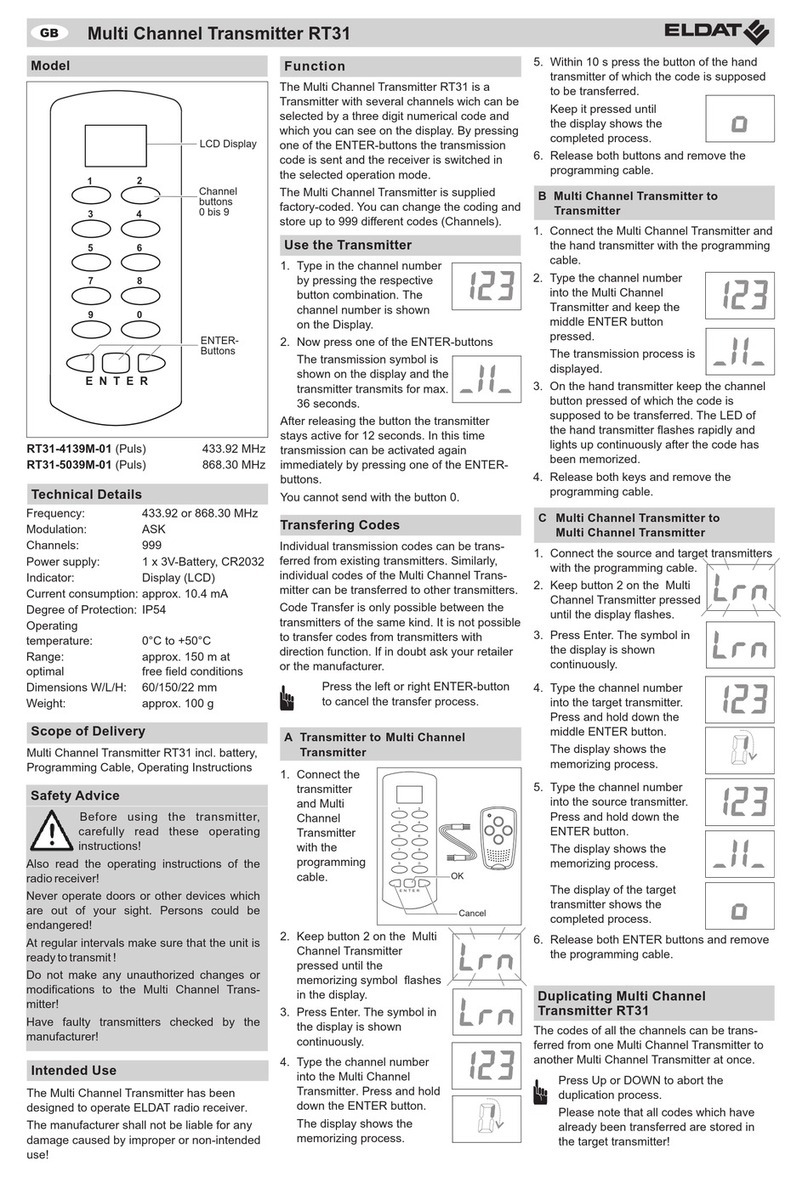
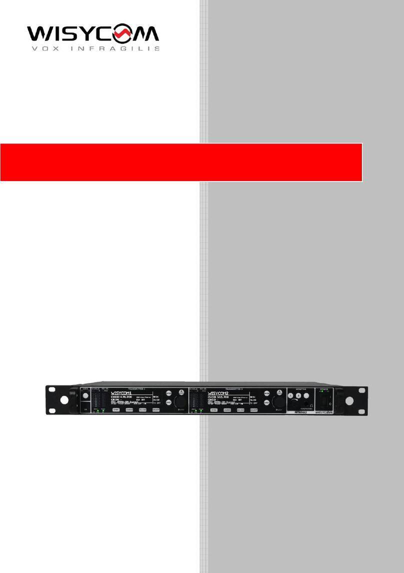
Keysight Technologies E6960A 1000Base-T1 User manual

Keysight E6960A
1000Base-T1 Transmitter
Compliance Application
User Guide and
Method of
Implementation

2 Keysight E6960A User Guide and Method of Implementation
Notices
Copyright Notice
© Keysight Technologies 2017 - 2019
No part of this manual may be repro-
duced in any form or by any means
(including electronic storage and
retrieval or translation into a foreign
language) without prior agreement and
written consent from Keysight Technol-
ogies as governed by United States and
international copyright laws.
Trademarks
[Relevant acknowledgements should
be included here. Reference “LA-403
When to Use the Trademark Symbol
and Other Trademark Acknowledge-
ments” for guidance. If no acknowl-
edgements are required, remove the
caption.]
Manual Part Number
E6960-90001
Edition
Edition 3.0, March 2019
Printed in:
Printed in Malaysia
Published by:
Keysight Technologies
Bayan Lepas Free Industrial Zone,
11900 Penang, Malaysia
Technology Licenses
The hardware and/or software
described in this document are fur-
nished under a license and may be
used or copied only in accordance with
the terms of such license.
Declaration of Conformity
Declarations of Conformity for this
product and for other Keysight prod-
ucts may be downloaded from the
Web. Go to http://www.keysight.com/
go/conformity. You can then search by
product number to find the latest Dec-
laration of Conformity.
U.S. Government Rights
The Software is “commercial computer
software,” as defined by Federal Acqui-
sition Regulation (“FAR”) 2.101. Pursu-
ant to FAR 12.212 and 27.405-3 and
Department of Defense FAR Supple-
ment (“DFARS”) 227.7202, the U.S.
government acquires commercial com-
puter software under the same terms
by which the software is customarily
provided to the public. Accordingly,
Keysight provides the Software to U.S.
government customers under its stan-
dard commercial license, which is
embodied in its End User License
Agreement (EULA), a copy of which can
be found at http://www.keysight.com/
find/sweula. The license set forth in the
EULA represents the exclusive authority
by which the U.S. government may use,
modify, distribute, or disclose the Soft-
ware. The EULA and the license set
forth therein, does not require or per-
mit, among other things, that Keysight:
(1) Furnish technical information
related to commercial computer soft-
ware or commercial computer software
documentation that is not customarily
provided to the public; or (2) Relinquish
to, or otherwise provide, the govern-
ment rights in excess of these rights
customarily provided to the public to
use, modify, reproduce, release, per-
form, display, or disclose commercial
computer software or commercial com-
puter software documentation. No
additional government requirements
beyond those set forth in the EULA
shall apply, except to the extent that
those terms, rights, or licenses are
explicitly required from all providers of
commercial computer software pursu-
ant to the FAR and the DFARS and are
set forth specifically in writing else-
where in the EULA. Keysight shall be
under no obligation to update, revise or
otherwise modify the Software. With
respect to any technical data as
defined by FAR 2.101, pursuant to FAR
12.211 and 27.404.2 and DFARS
227.7102, the U.S. government
acquires no greater than Limited Rights
as defined in FAR 27.401 or DFAR
227.7103-5 (c), as applicable in any
technical data.
Warranty
THE MATERIAL CONTAINED IN THIS
DOCUMENT IS PROVIDED “AS IS,”
AND IS SUBJECT TO BEING
CHANGED, WITHOUT NOTICE, IN
FUTURE EDITIONS. FURTHER, TO THE
MAXIMUM EXTENT PERMITTED BY
APPLICABLE LAW, KEYSIGHT DIS-
CLAIMS ALL WARRANTIES, EITHER
EXPRESS OR IMPLIED, WITH REGARD
TO THIS MANUAL AND ANY INFORMA-
TION CONTAINED HEREIN, INCLUD-
ING BUT NOT LIMITED TO THE
IMPLIED WARRANTIES OF MER-
CHANTABILITY AND FITNESS FOR A
PARTICULAR PURPOSE. KEYSIGHT
SHALL NOT BE LIABLE FOR ERRORS
OR FOR INCIDENTAL OR CONSE-
QUENTIAL DAMAGES IN CONNECTION
WITH THE FURNISHING, USE, OR
PERFORMANCE OF THIS DOCUMENT
OR OF ANY INFORMATION CON-
TAINED HEREIN. SHOULD KEYSIGHT
AND THE USER HAVE A SEPARATE
WRITTEN AGREEMENT WITH WAR-
RANTY TERMS COVERING THE MATE-
RIAL IN THIS DOCUMENT THAT
CONFLICT WITH THESE TERMS, THE
WARRANTY TERMS IN THE SEPARATE
AGREEMENT SHALL CONTROL.
Safety Information
CAUTION
A CAUTION notice denotes a hazard. It
calls attention to an operating proce-
dure, practice, or the like that, if not
correctly performed or adhered to,
could result in damage to the product
or loss of important data. Do not pro-
ceed beyond a CAUTION notice until
the indicated conditions are fully
understood and met.
WARNING
A WARNING notice denotes a hazard. It
calls attention to an operating proce-
dure, practice, or the like that, if not
correctly performed or adhered to,
could result in personal injury or death.
Do not proceed beyond a WARNING
notice until the indicated conditions are
fully understood and met.

Keysight E6960A User Guide and Method of Implementation 3
Table of Contents
1Overview
Introduction . . . . . . . . . . . . . . . . . . . . . . . . . . . . . . . . . . . . . . . . . . . . . .10
Installing the Compliance Test Solution Software . . . . . . . . . . . . . .12
Installing the License Key . . . . . . . . . . . . . . . . . . . . . . . . . . . . . . . . .12
Preparing to Take Measurements . . . . . . . . . . . . . . . . . . . . . . . . . . . . .13
Calibrate the Oscilloscope . . . . . . . . . . . . . . . . . . . . . . . . . . . . . . . . .13
General Test Setup . . . . . . . . . . . . . . . . . . . . . . . . . . . . . . . . . . . . . .14
Starting the Automotive Ethernet Compliance Test Solution Software 18
Top Menu Bar . . . . . . . . . . . . . . . . . . . . . . . . . . . . . . . . . . . . . . . . . . .24
Tabs . . . . . . . . . . . . . . . . . . . . . . . . . . . . . . . . . . . . . . . . . . . . . . . . . .24
Test Mode 1. TX_TCLK125 Frequency and Transmit Jitter Tests . . . . .25
Test Setup . . . . . . . . . . . . . . . . . . . . . . . . . . . . . . . . . . . . . . . . . . . . .25
Specification References . . . . . . . . . . . . . . . . . . . . . . . . . . . . . . . . . .25
TX_TCLK125 Frequency Test . . . . . . . . . . . . . . . . . . . . . . . . . . . . . . .25
Transmit Clock Jitter (MASTER/SLAVE) . . . . . . . . . . . . . . . . . . . . . .26
Test Mode 2. Transmit Clock Frequency (MASTER) and MDI Output Jitter
(MASTER) Tests . . . . . . . . . . . . . . . . . . . . . . . . . . . . . . . . . . . . . . . . .27
Test Setup . . . . . . . . . . . . . . . . . . . . . . . . . . . . . . . . . . . . . . . . . . . . .27
Specification References . . . . . . . . . . . . . . . . . . . . . . . . . . . . . . . . . .27
Transmit Clock Frequency . . . . . . . . . . . . . . . . . . . . . . . . . . . . . . . . .27
MDI Output Jitter (MASTER) . . . . . . . . . . . . . . . . . . . . . . . . . . . . . . .27
Test Mode 4. Transmitter Distortion and MDI Return Loss . . . . . . . . . .29
Test Setup . . . . . . . . . . . . . . . . . . . . . . . . . . . . . . . . . . . . . . . . . . . . .29
Using the Optional E6960A Frequency Divider Board . . . . . . . . . . .30
Specification References . . . . . . . . . . . . . . . . . . . . . . . . . . . . . . . . . .30
Transmitter Distortion Tests Information . . . . . . . . . . . . . . . . . . . . .30
Transmitter Distortion Enhance Clock Recovery Algorithm . . . . . . .31
MDI Return Loss Test . . . . . . . . . . . . . . . . . . . . . . . . . . . . . . . . . . . . .32
Test Setup . . . . . . . . . . . . . . . . . . . . . . . . . . . . . . . . . . . . . . . . . . . . .33
MDI Return Loss Test Information . . . . . . . . . . . . . . . . . . . . . . . . . . .35
Test Mode 5. Transmitter Power Spectral Density, Transmitter Power Level

4 Keysight E6960A User Guide and Method of Implementation
and Transmitter Peak Differential Output Tests . . . . . . . . . . . . . . . . 36
Test Setup . . . . . . . . . . . . . . . . . . . . . . . . . . . . . . . . . . . . . . . . . . . . . 36
Specification References . . . . . . . . . . . . . . . . . . . . . . . . . . . . . . . . . . 37
Transmitter Power Spectral Density (PSD) . . . . . . . . . . . . . . . . . . . . 38
Transmitter Power Level . . . . . . . . . . . . . . . . . . . . . . . . . . . . . . . . . . 39
Transmitter Peak Differential Output . . . . . . . . . . . . . . . . . . . . . . . . 39
Test Mode 6. Output Droop Tests . . . . . . . . . . . . . . . . . . . . . . . . . . . . . 40
Test Setup . . . . . . . . . . . . . . . . . . . . . . . . . . . . . . . . . . . . . . . . . . . . . 40
Specification References . . . . . . . . . . . . . . . . . . . . . . . . . . . . . . . . . . 40
Transmitter Output Droop Positive Test Information . . . . . . . . . . . . 40
Transmitter Output Droop Negative Test Information . . . . . . . . . . . 41
Viewing the Test Report . . . . . . . . . . . . . . . . . . . . . . . . . . . . . . . . . . . . . 42
Reference Documents . . . . . . . . . . . . . . . . . . . . . . . . . . . . . . . . . . . . . . 44
Other Keysight Automotive Ethernet Applications and Software . . 44
A Setting Up the N5395C Ethernet Transmitter Test Fixture
Introduction . . . . . . . . . . . . . . . . . . . . . . . . . . . . . . . . . . . . . . . . . . . . . . 46
Jumper Settings . . . . . . . . . . . . . . . . . . . . . . . . . . . . . . . . . . . . . . . . 48
B Configure External Instruments
Introduction . . . . . . . . . . . . . . . . . . . . . . . . . . . . . . . . . . . . . . . . . . . . . . 52
C External Instrument Calibration
Introduction . . . . . . . . . . . . . . . . . . . . . . . . . . . . . . . . . . . . . . . . . . . . . . 56
Calibrating the AWG . . . . . . . . . . . . . . . . . . . . . . . . . . . . . . . . . . . . . 56
Calibrating the ENA . . . . . . . . . . . . . . . . . . . . . . . . . . . . . . . . . . . . . . 59
D Using the E6960-66600 Frequency Divider Board
Introduction . . . . . . . . . . . . . . . . . . . . . . . . . . . . . . . . . . . . . . . . . . . . . . 64
Static-safe Handling Procedures . . . . . . . . . . . . . . . . . . . . . . . . . . . 65
Frequency Divider Board Test Setup . . . . . . . . . . . . . . . . . . . . . . . . 67
Connector Description . . . . . . . . . . . . . . . . . . . . . . . . . . . . . . . . . . . 68
DIP Switch Description . . . . . . . . . . . . . . . . . . . . . . . . . . . . . . . . . . . 69
LED Description . . . . . . . . . . . . . . . . . . . . . . . . . . . . . . . . . . . . . . . . 70

Keysight E6960A User Guide and Method of Implementation 5
List of Figures
Figure 1-1 Connection to the Oscilloscope Using a Pair of SMA
Cables . . . . . . . . . . . . . . . . . . . . . . . . . . . . . . . . . . .15
Figure 1-2 Connection to the Oscilloscope using a Differential
Probe . . . . . . . . . . . . . . . . . . . . . . . . . . . . . . . . . . . .16
Figure 1-3 General Test Setup using the N5395C Evaluation Board
17
Figure 1-4 Launching the E6960A Compliance Test Application .
18
Figure 1-5 E6960A 1000Base-T1 Compliance Test Application Main
Window . . . . . . . . . . . . . . . . . . . . . . . . . . . . . . . . . .19
Figure 1-6 Select Tests Menu with all tests selected . . . . . . . . . .20
Figure 1-7 Configure Tab for Test Mode 1 . . . . . . . . . . . . . . . . . .22
Figure 1-8 Connect Tab for Test Mode 1 . . . . . . . . . . . . . . . . . . . .23
Figure 1-9 Connection for Transmitter Distortion Test Using Keysight
81150A Function Generator . . . . . . . . . . . . . . . . . .29
Figure 1-10 Single Ended Connection Setup for MDI Return Loss
Test . . . . . . . . . . . . . . . . . . . . . . . . . . . . . . . . . . . . .33
Figure 1-11 Differential Connection Setup for MDI Return Loss Test
34
Figure 1-12 Power Spectral Density Test Using N9010B Signal
Analyzer . . . . . . . . . . . . . . . . . . . . . . . . . . . . . . . . . .36
Figure 1-13 Typical Results Tab . . . . . . . . . . . . . . . . . . . . . . . . . . .42
Figure 1-14 Top Portion of a Typical HTML Report . . . . . . . . . . . . .43
Figure A-1 N5395C Ethernet Electrical Transmitter Test Fixture .47
Figure A-2 Return Loss Impedance Calibration Board . . . . . . . . .47
Figure A-3 Section 11 on the Ethernet Test Fixture. . . . . . . . . . . .48
Figure A-4 Jumper Location for Ethernet Test Fixture . . . . . . . . .49
Figure B-1 E6960A Compliance Test Application Main Menu . . .52
Figure B-2 BroadR-Reach Compliance Test Application External In-
struments List . . . . . . . . . . . . . . . . . . . . . . . . . . . . .53
Figure C-1 AWG Calibration Setup for the Disturbing Signal Source
57
Figure C-2 E6960A Compliance Test Application Main Menu . . .58
Figure C-3 ENA Calibration Setup (Return Loss) . . . . . . . . . . . . . .59

6 Keysight E6960A User Guide and Method of Implementation
Figure C-4 ENA Calibration Setup (ECal Module) . . . . . . . . . . . . . 61
Figure D-1 Keysight’s E6960-66600 Frequency Divider Board . . 64
Figure D-2 Check the Use 10MHz Ref Clock on Main Application
Window . . . . . . . . . . . . . . . . . . . . . . . . . . . . . . . . . . 66
Figure D-3 Test Setup for 10 MHz Frequency Reference . . . . . . . 67

Keysight E6960A User Guide and Method of Implementation 7
List of Tables
Table 1-1 Test Modes . . . . . . . . . . . . . . . . . . . . . . . . . . . . . . . . . .10
Table 1-2 Tabs Menu functions . . . . . . . . . . . . . . . . . . . . . . . . . .21
Table A-1 List of Compliance Test Board Sections . . . . . . . . . . .46
Table D-1 Switch A function states . . . . . . . . . . . . . . . . . . . . . . .69
Table D-2 Switch B function states . . . . . . . . . . . . . . . . . . . . . . .70
Table D-3 LED indicators . . . . . . . . . . . . . . . . . . . . . . . . . . . . . . .70
Table D-4 LED A indicators . . . . . . . . . . . . . . . . . . . . . . . . . . . . . .71
Table D-5 LED B indicators . . . . . . . . . . . . . . . . . . . . . . . . . . . . . .71

8 Keysight E6960A User Guide and Method of Implementation
THIS PAGE HAS BEEN INTENTIONALLY LEFT BLANK.

Keysight E6960A 1000Base-T1 Transmit Compliance Solution
User Guide and Method of Implementation
9
1 Overview
Introduction 10
Preparing to Take Measurements 13
Starting the Automotive Ethernet Compliance Test Solution Software 18
Test Mode 1. TX_TCLK125 Frequency and Transmit Jitter Tests 25
Test Mode 2. Transmit Clock Frequency (MASTER) and MDI Output Jitter
(MASTER) Tests 27
Test Mode 4. Transmitter Distortion and MDI Return Loss 29
Test Mode 5. Transmitter Power Spectral Density, Transmitter Power Level and
Transmitter Peak Differential Output Tests 36
Test Mode 6. Output Droop Tests 40
Viewing the Test Report 42
Reference Documents 44

1Overview
10 Keysight E6960A User Guide and Method of Implementation
Introduction
Testing a 1000Base-T1 PHY's transmitter is accomplished through the use of
various test modes defined in the 1000Base-T1 specification. See “Reference
Documents” on page 44.
Keysight’s E6960A 1000Base-T1 TX Compliance Application Software (provided
as a software option to the E6961A Automotive Ethernet Solution) provides five
test modes for the testing and validating the transmitter waveform, transmitter
distortion, transmitted jitter, and transmitter droop. The test modes change only
the data symbols provided to the transmitter circuitry and do not alter the
electrical and jitter characteristics of the transmitter and receiver from those of
normal operation.
Using the Keysight E6960A 1000Base-T1 Compliance application software along
with an N5395C Ethernet Test Fixture greatly simplifies compliance testing. The
software automatically configures all of the required test equipment reducing the
overall test time.
The E6960A Software:
– Lets you select individual or multiple test to run.
Table 1-1 Test Modes
Test Mode Description
1 Setting Master and Slave PHYs for Transmit Clock Jitter in Linked Mode
2 Transmit MDI jitter test in MASTER mode
3 Not Used
4 Transmitter distortion test
5Normal Operation in Idle Mode. Power Spectral Density (PSD) mask and power level test.
6 Transmitter Droop Test
NOTE
This E6960A User Guide is written as a guide to using the E6960A 1000Base-T1
TX Compliance Application software.

Overview 1
Keysight E6960A User Guide and Method of Implementation 11
– Lets you identify the device being tested and its configuration.
– Shows you how to make oscilloscope connections to the device under test.
– Automatically checks for proper oscilloscope configuration.
– Automatically sets up the oscilloscope for each test.
– Allows you to determine the number of trials for averaging in each test.
– Provides detailed information of each test that has been run. The result of
maximum 64 worst trials can be displayed at any one time.
– Creates a printable HTML report of the tests that have been run. This report
includes pass/fail limits, margin analysis, and screen captures.

1Overview
12 Keysight E6960A User Guide and Method of Implementation
Installing the Compliance Test Solution Software
1Make sure you have the minimum version of Infiniium oscilloscope software
(see the software release notes) by choosing Help > About Infiniium... from the
main menu.
2To obtain the E6960A Compliance Application software, go to Keysight
website: http://www.keysight.com/find/E6960A.
3Click the Trials & Licenses tab.
4Click the Details & Download button.
5Read and verify the Prerequisites and installation information. Follow the
instructions to download and install the application software. Click the red
Download button.
Installing the License Key
1Request a license code from Keysight by following the instructions on the
Entitlement Certificate. You will need the oscilloscope's “Option ID Number”,
which you can find in the Help > About Infiniium... dialog box.
2After you receive your license code from Keysight, choose Utilities > License
Manager > Legacy Licenses.... Depending on the license acquired, select
either Local License or Server License.
3In the Install Option License dialog box, enter your license code and click
Install License. Additional information is required for server based licensing.
Please refer to your entitlement.
4Click OK in the dialog box that tells you to restart the Infiniium oscilloscope
application software to complete the license installation.
5Click Close to close the Install Option License dialog box.
6Choose File > Exit.
7Restart the Infiniium oscilloscope application software to complete the license
installation.
You can also install the license using Keysight License Manager. For detailed
instructions, refer to the online help for the Keysight License Manager.

Overview 1
Keysight E6960A User Guide and Method of Implementation 13
Preparing to Take Measurements
Before running the E6960A automated compliance tests, you should calibrate the
oscilloscope and probe. After calibrating the oscilloscope and probe, you are
ready to start the Compliance Test Application and perform the measurements.
Calibrate the Oscilloscope
For information on performing the internal diagnostic and calibration cycle for
your Keysight Infiniium oscilloscope, refer to the "User Calibration" topic in your
oscilloscope's online help.
Probe Calibration
Before performing the automated tests, you should calibrate the probes.
Calibration of the solder-in probe heads consists of a vertical calibration and a
skew calibration. The vertical calibration should be performed before the skew
calibration. Both calibrations should be performed for best probe measurement
performance.
For information on performing probe vertical and skew calibration in your Keysight
Infiniium oscilloscope, refer to the "DC Attenuation/Offset Calibration" and "Skew
Calibration" topics in your oscilloscope's online help.
For more information on calibration/deskew procedures for your particular probe,
refer to the probe's user's guide in the Keysight Probe Resource Center.
NOTE
If the ambient temperature changes more than 5 °C from the calibration
temperature, internal calibration should be performed again. The delta between
the calibration temperature and the present operating temperature is shown in
the Utilities > Calibration menu.
NOTE
If you switch cables between channels or other oscilloscopes, it is necessary to
perform cable and probe calibration again. Keysight recommends that, once
calibration is performed, you label the cables with the channel on which they
were calibrated.

1Overview
14 Keysight E6960A User Guide and Method of Implementation
General Test Setup
Test Modes 1, 2, 5, and 6 require only the Infiniium oscilloscope and the device to
be tested (Device Under Test or DUT). The test setup is described below.
Differential Signal supplied to the Oscilloscope can be achieved either by using
Two Oscilloscope Channels or a Single Differential Probe. The type of
connection accepted can be selected in the Setup tab of the test application.
Two Oscilloscope Channels refers to connecting the differential automotive pair
to the oscilloscope using only SMA cables. Refer to Figure 1-1 for more details.
Single Differential Probe refers to connecting the differential automotive pair to
the Oscilloscope using a single differential probe. Refer to Figure 1-2 for more
details. The only variation would be the Power Level Test that requires a balun.
Any variation from the above definition of differential signaling type is not
recommended.
Test Mode 4 requires the N5395C Ethernet Test Fixture and an Arbitrary
Waveform Generator (AWG). Refer to “Test Mode 4. Transmitter Distortion and
MDI Return Loss” on page 29 for specific setup details.
Test Mode 4 also includes an MDI S-Parameter Test.
Test Mode 5 can also use the N9010B Signal Analyzer. Refer to “Test Mode 5.
Transmitter Power Spectral Density, Transmitter Power Level and Transmitter
Peak Differential Output Tests” on page 36 for specific setup details.
NOTE
For all tests, use the software supplied with your transmitter PHY to control the
Device Under Test.

Overview 1
Keysight E6960A User Guide and Method of Implementation 15
Two Oscilloscope Channels Connection to Oscilloscope
Two SMA cables are needed to directly connect the output of the transmitter to
the oscilloscope. The specific oscilloscope channel used can be selected in the
Configure tab of the application.
An optional TX_TCLK may be supplied to the oscilloscope to run the tests.
Figure 1-1 Connection to the Oscilloscope Using a Pair of SMA Cables
Transmitter
under test
TX+
TX-
100
SMA Cables
Transmitter Clock to oscilloscope Ref Clock In

1Overview
16 Keysight E6960A User Guide and Method of Implementation
Single Differential Probe Connection to Oscilloscope
A differential probe is used to connect the output of the transmitter to the
oscilloscope. The specific oscilloscope channel used can be selected in the
Configure tab of the application.
An optional TX_TCLK may be supplied to the oscilloscope to run the tests.
Figure 1-2 Connection to the Oscilloscope using a Differential Probe
Transmitter
under test
TX+
TX-
100
High
Impedance
Differential
Probe
Transmitter Clock to oscilloscope Ref Clock In

Overview 1
Keysight E6960A User Guide and Method of Implementation 17
Connection Using the N5395C Ethernet Transmitter Test Fixture
Alternately, you can use Section 1 of the N5395C Ethernet 10/100/1G Transmitter
Electrical Test Fixture to make connections to the Transmitter under test. The
SMA connections shown are for wire pair A (DA+ and DA–). This connection is only
valid if the DUT has an RJ45 connector. To test to wire pair B, C, or D, connect the
oscilloscope SMA cables to the appropriate Evaluation Board SMA connectors.
See Figure 1-3 below. In the event the DUT does not have an RJ45 connector,
user will need to replace Section 1 with any adapter that converts the differential
automotive pair to SMA.
Figure 1-3 General Test Setup using the N5395C Evaluation Board
BNC to
SMA
Cables
D+ D-
Transmitter
Under Test
(DUT)
RJ45 CAT5e LAN Cable N5395C Ethernet Transmitter Test Fixture

1Overview
18 Keysight E6960A User Guide and Method of Implementation
Starting the Automotive Ethernet Compliance Test Solution
Software
1Ensure that the 1000Base-T1 Device Under Test (DUT) transmitter is operating
and set to desired test modes.
2To start the Compliance Test Application from the Infiniium oscilloscope's main
menu, select Analyze > Automated Test Apps > E6960A 1000Base-T1 Test
App.
Figure 1-4 Launching the E6960A Compliance Test Application

Overview 1
Keysight E6960A User Guide and Method of Implementation 19
Figure 1-5 E6960A 1000Base-T1 Compliance Test Application Main
Window
3Figure 1-5 above shows the E6960A 1000Base-T1 Compliance Test
Application main window.
4The Compliance Application software automatically sets frequency, etc. of the
external instruments (oscilloscope, ENA, generators, etc.) if they are properly
configured. Refer to Appendix B, “Configure External Instruments” on page 51.
1
2
3
4
Item Description
1Use TX_CLK. Check this if your DUT has its own Transmit Clock. Otherwise, the default clock signal is
used.
2Requires Frequency Divider Board. Refer Appendix D “Using the E6960-66600 Frequency Divider
Board” on page 63
3 Refer to Appendix C “External Instrument Calibration” on page 55
4 Refer to Appendix B “Configure External Instruments” on page 51

1Overview
20 Keysight E6960A User Guide and Method of Implementation
5The task flow pane, and the tabs in the main pane, show the steps you take in
running the automated tests.
Figure 1-6 Select Tests Menu with all tests selected
6Figure 1-6 above shows all the tests that are available in E6960A 1000Base-T1
Compliance Test Application.
Displays test limits, test description, and IEEE
specification reference for the selected test.
Table of contents
