Kia 3WF60 AQ700 User manual

1
2
3
4
5
6
7
8
9
10
Torque Wrench
Wire CutterTrim Removal Tool
Denotes safety equipment required to be used, such as a
mask, safety glasses, gloves or hearing protection.
Hood Lever Tool
Extension
Phillips Screwdriver
Ratchet 10mm Socket 12mm Socket 8mm Socket
Note: Difficulty stated above reflects the minimum level of expertise required to install the
accessory: ( A ) Customer ( B ) Dealer Technician ( C ) Master Technician
Instructional Symbols / Definitions
If vehicle does not have the following standard equipment, DO NOT PROCEED WITH INSTALLATION:
automatic transmission, power doors & locks, smart key and push button ignition system.
Installation Restrictions
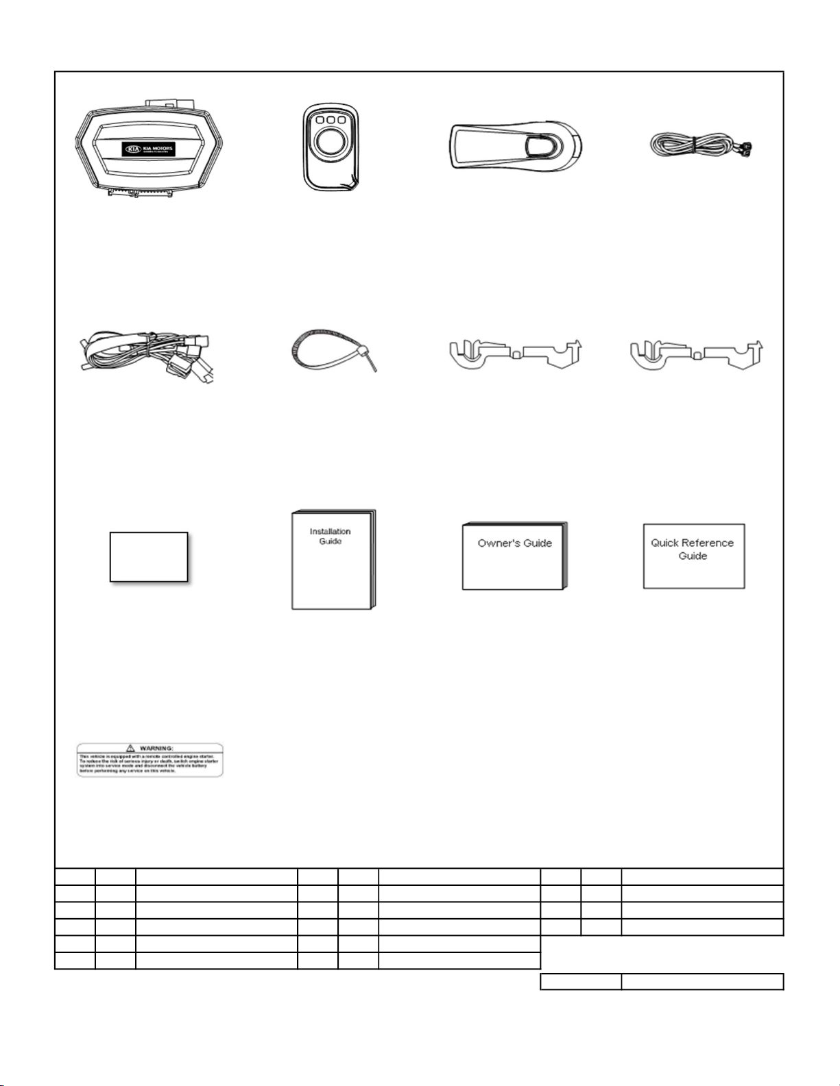
Part No.:
3WF60 AQ700
Vehicle Model:
Sportage
Model Year:
2014 ~
Difficulty:
Accessory:
( B )
Remote Engine Start - Push Start
Genuine Accessories
Technical Support
Hours: 9:00 a.m. - 5:00 p.m. EST Monday - Friday
For Authorized Dealers: 855-225-7344
Notes to the installer
Read the entire installation manual prior to beginning the installation of the accessory.
Ensure that the vehicle is properly protected in the area that the accessory is to be installed.
To prevent vehicle damage, never place tools on top of painted surfaces, seats, dash pad, console or floor carpet / mat.
Always wear appropriate safety equipment, including gloves and eye protection when required.
Prior to disconnecting the negative lead to the battery, note the AM/FM and satellite radio set frequenecies on the inspection page, if applicable.
To prevent stress on the remote start wire harness, ensure the tilt/telescope steering column is fully extended, if equipped.
Ensure the transportation fuse is properly installed before performing the function check.
Open driver’s door window.
Vehicle should be at room temperature.
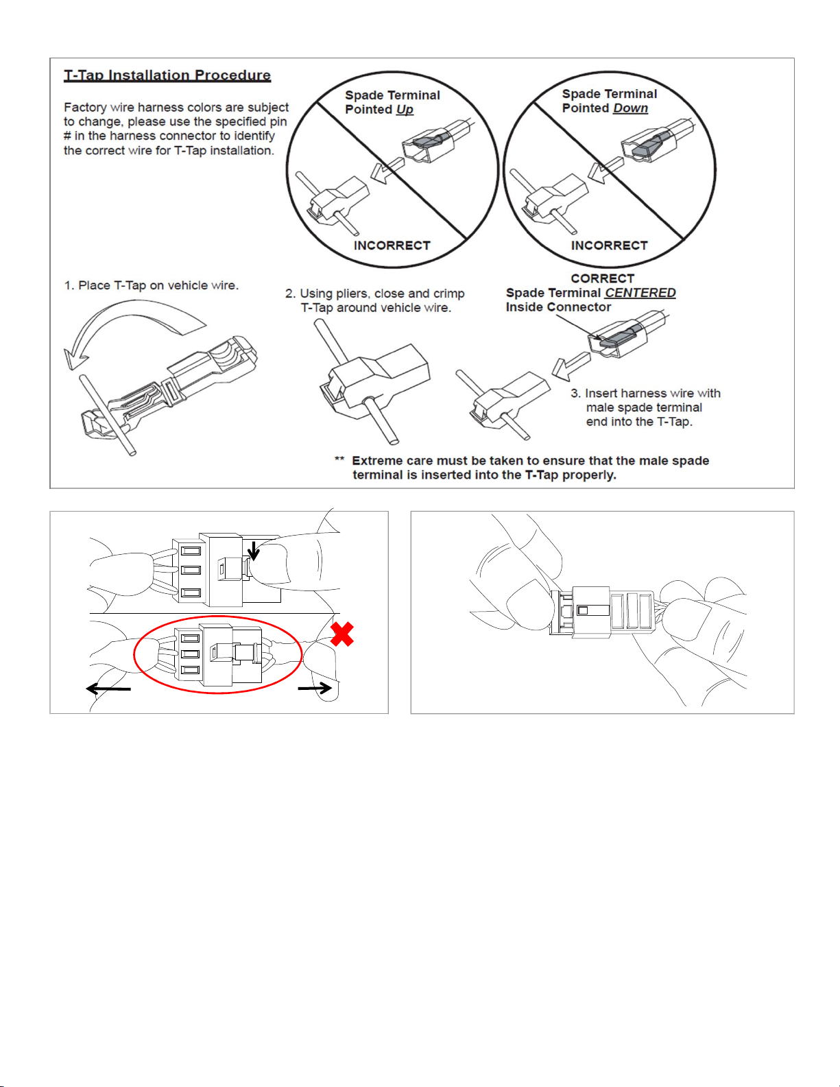
Factory wire harness colors are subject to change. Please use the specified pin # in the harness connector to identify the correct wire for tapping.
Pliers
Denotes warnings that may lead to
serious physical injury or vehicle
damage.
Denotes cautions to be taken to
avoid physical injury or electronic
component damage.
Denotes cautions to be taken to
avoid vehicle or component damage.
Clean Cloth
50/50 Isopropyl Alcohol
(70%) & Water
Basic Required Hand Tools
Denotes quality processes to be
checked prior to moving to the next
step.
Denotes specific tools that are
necessary to complete the step.
Denotes instructional steps
necessary to complete the process.
Safety Glasses
Hearing Protection
Mask
Gloves
N
O
T
Revision Date
08/10/2016 Page 1 of 18

* Extra components intentionally placed in kit as spares.
Please follow directions for proper placement of each component.
5. 1 Main Harness 10. 1 Installation Guide
4. 1 Antenna Harness 9. 3 Foam Tape
3. 1 Antenna 8. 2 Female T-tap (Red)* 13. 1 Warning Label
2. 2 Remote Transmitter 7. 3 Female T-Tap (Yellow)* 12. 1 Quick Reference Guide
1. 1 Main Controller Module 6. 23 Cable Tie* 11. 1 Owner's Guide
No. Qty. Description No. Qty. Description No. Qty. Description
Warning Label
⑬
⑨⑩⑪⑫
Genuine Accessories
Kit Overview
①②③④
P/N: 3WF60 AQ701MC P/N: 3WF60 AQ700RT P/N: 3WF60 AQ700AT P/N: 3WF60 AQ700AH
⑤⑥⑦⑧
41 TOTAL
Main Controller Module Remote Transmitter Antenna Antenna Harness
Main Harness Cable Tie Female-T-Tap (Yellow) Female T-Tap (Red)
Foam Tape Installation Guide Owner's Guide Quick Reference Guide
P/N: 3WF60 AQ700MH
Revision Date
08/10/2016 Page 2 of 18

Special Procedures
Disconnecting Connectors
Lock Connectors
When disconnecting connectors, grasp the connectors , not the wire When locking connectors, listen for a click indicating
they are securely locked.
Genuine Accessories
NO GOOD
"CLICK"
When disconnecting connectors, press the lock tab and pull apart by
grasping the connectors. DO NOT PULL ON WIRES.
GOOD
Revision Date
08/10/2016 Page 3 of 18

Store the removed parts in a safe location to prevent damage.
4
N
O
T
E
1. Dislodge the Weatherstrip at the Dash End Cap Panel area.
2. Remove the Fuse Panel Cover.
3. Using a Trim Removal Tool, remove the Driver Side Dash End Cap
Panel by prying outward to disengage the three (3) Pressure Clips.
N
O
T
E
1. Using a Phillips Screwdriver, remove the four (4) Phillips Screws
from the Lower Dash Panel as shown.
Trim Removal Tool 3Phillips Screwdriver
WARNING! Shock Hazard. Do not touch vehicle's negative
battery terminal to vehicle's positive battery terminal. Serious
physical injury or electronic component damage may occur.
Genuine Accessories
N
O
T
E
1. Locate the Hood Lever on the Driver's Kick Panel as shown above.
2. Pull the Hood Lever to open the Hood.
N
O
T
E
1. Using a Ratchet and 10 mm Socket, remove and isolate the
Negative Battery Cable from the Battery.
1Ratchet and 10mm Socket 2
Negative Battery
Cable
Fuse Panel Cover
Phillips
Screws
Dash End Cap Panel
Pressure
Clips
Revision Date
08/10/2016 4 of 18

CAUTION! Be careful not to damage the Steering Column Shroud when removing.
Store the removed part in a safe location to prevent damage.
N
O
T
E
1. Using a Phillips Screwdriver, remove the three (3) Phillips Screws securing the Steering Column Shroud, one (1) underneath and
two (2) behind the Steering Wheel. Turn the Steering Wheel for access.
2. Release the Steering Wheel Tilt Adjust Lever.
3. Using a Trim Removal Tool, pull down on the Steering Column Shroud Lower Cover to separate.
If applicable, disconnect the Steering Wheel Heater Switch Connector and dislodge the Connector Retainer Clip.
Remove the Steering Column Shroud Lower Cover.
4. Adjust the Telescoping Tilt Steering Column to the fully extended position and lock into place.
CAUTION! Be careful not to damage the Lower Dash Panel
when removing.
Store the removed part in a safe location to prevent damage.
WARNING! Knee bolster plate may be sharp.
Store the removed part in a safe location to prevent damage.
7
Phillips Screwdriver and Trim Removal Tool
Genuine Accessories
N
O
T
E
1. Using a Trim Removal Tool, carefully pry the Lower Dash Panel
outward to release the two (2) Retaining Tabs on the side and the
six (6) Pressure Clips.
2. Disconnect the OBDII Connector from the Lower Dash Panel.
3. Disconnect any remaining connectors, if equipped.
4. Pull upward and rearward to remove the Lower Dash Panel, taking
care to avoid damaging the Hidden Tab located behind the kick
panel, as shown.
N
O
T
E
1. Using a Ratchet, Extension and 10 mm Socket, remove
the five (5) 10 mm Bolts securing the Knee Bolster Plate.
Trim Removal Tool 5Ratchet, Extension and 10mm Socket 6
Retaining
Tabs
Bolts
Connector
Retainer Clip
3-Pin M94 Steering
Wheel Heater Switch
Connector
Hidden Tab
Steering Wheel Heater Switch
Pressure
Clips
Phillips
Screws
Revision Date
08/10/2016 5 of 18

Trim Removal Tool
Genuine Accessories
N
O
T
E
1. Using a Trim Removal Tool, carefully pry outward to release the three (3) Pressure Clips, then slide the Passenger Side Console Cover towards the rear to
release the one (1) Hook.
2. Remove the Passenger Side Console Cover from the vehicle.
CAUTION! Be careful not to damage the Passenger Side Console Cover when removing.
Store the removed part in a safe location to prevent damage.
1. Carefully dislodge the Weatherstrip from the Driver Side Kick Panel
and Front Door Step Sill area.
2. Using a Trim Removal Tool, remove the Driver Side Front Door
Step Sill Trim Panel by inserting the Trim Removal Tool under the Trim
Panel and prying upward to release the four (4) Clips and two (2)
Hooks.
N
O
T
E
1. Using an 8mm Socket or Hood Lever Tool, remove the Hood Latch
Release Lever by compressing the center post tabs while
simultaneously prying the lever away from the Kick Panel
using a Trim Removal Tool.
2. Remove the Driver Side Kick Panel by pulling inwards to release the
two (2) Pressure Clips.
CAUTION! Be careful not to damage the Driver Side Front Door
Step Still Trim when removing.
Store the removed part in a safe location to prevent damage.
CAUTION! Be careful not to damage the Hood Lever or the
driver's Kick Panel when removing.
Store the removed part in a safe location to prevent damage.
10
9
N
O
T
E
Trim Removal Tool 8Trim Removal Tool, 8mm Socket or Hood Lever Tool
Press Hood
Lever Tool or
8mm Socket onto
Tabs
Pressure Clips
Pressure
Clips
Hook Hook
Pressure
Clips
Passenger Side Console Cover
Clips
Hooks
Pry Lever using
Trim Removal
Tool
Revision Date
08/10/2016 6 of 18

N
O
T
E
CAUTION! Be careful not to damage the Passenger Kick
Panel when removing.
Store the removed part in a safe location to prevent damage.
1. Locate the one (1) 12-Pin Female Connector under the Steering Column.
2. Disconnect the 12-Pin Female Connector and plug in the corresponding Remote Start Harness Connectors.
3. Using one (1) Cable Tie, secure the 12-Pin Horn T-harness to Factory Harness, as shown above.
4. Using a Wire Cutter, trim off excess cable tie.
Wire Cutter
WARNING! Engine Stall Hazard. To prevent stress / damage to the Remote Start Wire Harness, ensure that it does not contact
any vehicle components or any sharp metal edges by adjusting the Tilt / Telescopic Steering Column in all positions.
N
O
T
E
13
1. Carefully dislodge the Weatherstrip from the Passenger Side Kick
Panel and Front Door Step Sill area.
2. Using a Trim Removal Tool, remove the Passenger Side Front
Door Step Sill Trim Panel by inserting the Trim Removal Tool under
the Trim Panel and prying upward to release the four (4) Clips and
two (2) Hooks.
N
O
T
E
1. Remove Passenger Kick Panel by pulling inwards to release the
two (2) Pressure Clips.
CAUTION! Be careful not to damage the Passenger Side Front
Door Step Sill Trim when removing.
Store the removed part in a safe location to prevent damage.
Genuine Accessories
12
Trim Removal Tool 11 Trim Removal Tool
Hooks
Clips
Pressure Clips
Cable Tie
Remote Start
T-harness
Connectors
12-Pin Female
Horn Connector
Steering Column M20-R
12-Pin Female
Horn Connector
Revision Date
08/10/2016 7 of 18

Genuine Accessories
N
O
T
E
*Refer to page 3 for T-Tap Installation Procedure.
1. Find the factory I/P-E 54-Pin Female Connector located behind the Fuse Panel.
2. Pull down the Lever to disconnect the connector.
3. Using a Wire Cutter, remove the existing Cable Tie while taking care not to cut the Wire Harness.
4. Remove the Harness Cover to identify the correct pin / wire and to allow access to the wire harness for T-Tap installation.
5. Using a Pliers, crimp the two (2) T-Taps (Yellow) at four (4) inches above the connector. One (1) T-Tap point is crimped on the Blue Wire located in pin #25
of the 54-pin I/P-E Female Connector and the other one is crimped on the White Wire located in pin #31 of the 54-pin I/P-E Female Connector.
6. Connect the Blue (IG1) wire from the Remote Start Harness to the Blue Wire (Pin #25 of the 54-pin I/P-E Female Connector) by engaging the T-Tap
and connect the White Wire (IG2) from the Remote Start Harness to the White Wire (Pin # 31 of the 54-pin I/P-E Female Connector) by engaging
the T-Tap.
7. Assemble the I/P-E 54-Pin Female Connector with the Harness Cover.
8. Using one (1) Cable Tie, secure the Harness Cover of I/P-E 54-Pin Female Connector to the Wires, as shown above.
9. Using a Wire Cutter, trim off excess cable tie.
10. Reconnect the I/P-E 54-Pin Female Connector Lever to the locked position and confirm the connector is fully locked into place.
There are two White Color Wires (Pin #31 and Pin #54). T-Tap point should be Pin #31.
Wire Cutter and Pliers 14
Blue Wire
Pin #25 (IG1)
T-Tap Install Point
Cable
Tie
I/P-E
54-Pin
Female
Connector
Terminal End View
White Wire
Pin #31 (IG2)
T-Tap Install Point
4 inch
25
31
Fuse Panel
(Backside)
I/P-E 54-Pin
Female
Connector
Harness Cover
Lever
4 inch
Lever
Blue Wire
Pin #25
(IG1)
White Wire
Pin #31
(IG2)
Revision Date
08/10/2016 8 of 18

N
O
T
E
16
1. Locate the BCM Module at the upper side of the Accelator Pedal.
2. There are four (4) connectors on the BCM Module. Disconnect the factory 20-pin M13-B Female Connector and then plug in the corresponding
Remote Start T-Harness Connectors.
3. Using one (1) Cable Tie, secure the Remote Start Horn T-Harness Connector to the Factory Harness.
4. Using a Wire Cutter, trim off excess cable tie.
Genuine Accessories
15
Wire Cutter
1. Locate the 1-Pin MDPS Connector at the Driver's Kick Panel area as shown above.
2. Press the tab to release the 1-Pin MDPS Female Connector.
3. Disconnect the Factory 1-Pin MDPS Female Connector and then plug in the corresponding Remote Start T-harness Connectors.
4. Using two (2) Cable Ties, secure the Remote Start Harness to the Factory Harness as shown above.
5. Using a Wire Cutter, trim off excess cable ties.
CAUTION! There are two (2) 20-pin connectors on the BCM Module. The 20 Pin M13-B BCM Connector is located at the lower rear side of the
BCM.
Make sure you connect the corresponding Remote Start T-harness Connector to the 20-Pin M13-B BCM Connector as shown.
Wire Cutter
N
O
T
E
Warning! Make sure that both connectors on the MDPS Remote Start T-Harness are fully seated and locked in place, otherwise power assist
steering may be lost.
Cable Ties
1-Pin MDPS
Female Connector
Remote Start
Harness
Remote
Start Horn
T-harness
Connector
Cable Tie
BCM
M13-C
Connector
Fuse
Panel
MDPS
M13-B
20-Pin Female
CAN Connector
MC51 1-Pin MDPS
Female Connector
Remote Start
T-harness
Connectors
Revision Date
08/10/2016 9 of 18

Genuine Accessories
Ratchet, Torque Wrench, Extension and 12mm Socket 17
N
O
T
E
1. Locate the Factory 24-Pin I/P-B Female START Connector and 3-Pin I/P-A Female Connector on the front side of Fuse Panel
2. Disconnect the Factory 3-Pin I/P-A Female Connector.
3. Disconnect the Factory 24-Pin Female START Connector and then plug in the corresponding Remote Start Harness Connector.
4. Route I/P-A 3-Pin Female Connector over the 24-pin T-harness and GROUND Wire, then reconnect to the Fuse Panel.
N
O
T
E
1. Using a Ratchet, Extension and 12 mm Socket, remove the 12 mm Bolt located below the A-Pillar adjacent to the Fuse Box at the Dash End Cap area.
Route the GROUND wire in front of the Fuse Box and through the opening as shown above. Insert the Bolt through the GROUND Wire Ring Terminal
and reinstall.
2. Using a Torque Wrench, Extension and 12 mm Socket, tighten the bolt to: 16.7 ~ 21.6 N.m (1.7 ~ 2.2 kgf.m, 12.3 ~ 15.9 lb-ft).
18
I/P-B 24-Pin
Female START
Connector
I/P-A
3-Pin Female
Connector
GROUND
Wire
Remote Start
24-Pin T-harness
Connectors
Bolt
Opening
GROUND
Wire
Fuse Panel
(Front)
I/P-A
3-Pin Female
Connector
Remote Start
24-Pin T-harness
Connectors
I/P-A
3-Pin Female
Connector
Revision Date
08/10/2016 10 of 18

1. Place the Main Controller Module on the left side of the Factory Harness / Grommet and using two (2) Cable Ties, secure to the Factory Harness as shown
above.
2. Using a Wire Cutter, trim off excess cable ties.
Pay attention not to allow other factory components to depress the antenna button.
Make sure wire harnesses do not interfere with driver's feet or pedals.
Wire Cutter 21
N
O
T
E
N
O
T
E
1. Connect the 6-pin Remote Start Harness Connector
(Opaque Color) to the Main Controller Module.
2. Connect the 10-pin Remote Start Harness Connector (White color)
to the Main Controller Module.
3. Connect the 6-pin Antenna Connector (Blue color) to the
Main Controller Module.
N
O
T
E
1. Remove the film from the double sided tape on the Antenna and
adhere to the top of the Main Controller Module as shown above.
2. Connect the 6-pin Antenna Connector (Black color) to the Antenna.
Make sure the connector is fully seated and locked.
3. Join the two (2) Cable Ties together and install around the Module
and Antenna to secure both parts together.
4. Using a Wire Cutter, trim off excess wire ties.
Ensure that each connector is fully seated on the Main Controller
Module and Ignition Switch Module.
Pay attention not to route Cable Ties over Antenna Button or
electrical connectors.
Genuine Accessories
19 Wire Cutter 20
Cable Tie Mounting Holes
Cable Ties
Main Controller Module
Factory
harness
Main Controller Module - Two (2) cable ties
"Run Cable Tie" through the each hole on Main
Controller Module and tie to vehicle harness.
Grommet
on Bulkhead
Opaque 6-Pin
Connector
Blue 6-Pin
Connector
White 10-Pin
Connector
Blue 6-Pin
Connector
Black 6-Pin
Connector
Cable Tie (2)
Revision Date
08/10/2016 11 of 18

Genuine Accessories
22
N
O
T
E
1. Run the Immobilizer Data Bypass Wire through the Driver Console Side Cover.
- Immobilizer Data Bypass Wire : T-Tap Connector (Red), T-Tap Wire (Blue).
2. Pull the Immobilizer Data Bypass Wire completely through to the Passenger's Console Side Cover.
3. Using two (2) Cable Ties, secure the Immobilizer Data Bypass Wire to the Factory Harness (BCM Module connector wires), as shown above.
4. Using a Wire Cutter, trim off excess cable ties.
Wire Cutter
23
1. Using eight (8) Cable Ties, secure the Remote Start Harness to the Vehicle Harnesses as shown above.
2. Using a Wire Cutter, trim off excess cable ties.
Make sure wire harnesses do not interfere with driver's feet or pedals.
Wire Cutter
N
O
T
E
Brake Pedal
Cable Ties
BCM
Driver's Console
Side Cover
Cable Ties
MDPS
Remote Start
Data Bypass Wire
Accelerator
Pedal
Revision Date
08/10/2016 12 of 18

Make sure wire harnesses do not interfere with passenger's feet.
Genuine Accessories
24
N
O
T
E
*Refer to page 3 for T-Tap Installation Procedure.
1. Locate the 24-Pin Female Connector (Yellow) located at the Passenger Side Kick Panel,
The circuit colors are: Vehicle side (Blue) = Remote Start Harness (Blue).
2. Using one (1) provided T-Tap (Red), install on the Blue Wire in pin #7 of MC11 24-Pin Female Connector, then use a Pliers to close
and crimp the T-Tap to the Wire.
3. Route the Blue Wire of the Remote Start Harness to the T-Tap, then insert the spade end of the Remote Start Harness to the T-Tap Connector.
4. Please refer to Page 3 for further T-Tap installation details.5. Using one (1) Cable Tie, secure the Remote Start Harness to the Factory Harness as shown above.
5. Using a Wire Cutter, trim off excess cable tie.
Wire Cutter and Pliers
2625 Clean Cloth, 50/50 Mix of Isopropyl Alcohol (70%) and
Water
Wire Cutter
N
O
T
E
Make sure Remote Start Wire harness is hidden under the carpet
and does not interfere with passenger's feet.
1. Carefully pull back the Passenger Kick Side Floor Carpet.
2. Using three (3) Foam Tapes, secure the Immobilizer Data Bypass
Wire, as shown above.
3. Using one (1) Cable Tie, secure the Immobilizer Data Bypass Wire to the
Factory Harness as shown above.
4. Using a Wire Cutter, trim excess Cable Tie.
5. Reinstall the Passenger Kick Side Floor Carpet.
N
O
T
E
1. Using 50/50 Isopropyl Alcohol (70%) and Water Mix, clean the top
surface of the Radiator Core Support. Ensure that the surface is
completely dry.
2. Remove the backing on the provided one (1) Warning Label and
secure in place as shown above.
MC11 24-Pin Female
Connector
Terminal End View
24-Pin Female
Connector (Yellow)
Cable Tie
Factory Harness
Foam Tapes
Cable Tie
Remote Start Wire
Factory
Harness
Warning Label
T-Tap (Red)
Remote Start
Immobilizer Data Bypass
Wire (Blue)
Revision Date
08/10/2016 13 of 18

Genuine Accessories
Ratchet and 10mm Socket 27 Torque Wrench and 10mm Socket 28
N
O
T
E
1. Reconnect the Negative Battery Cable.
2. Test LOCK/UNLOCK function using the Smart Key Fob.
3. Get in the vehicle with the Smart Key Fob, then press the Brake Pedal and
push the START Button to start the engine.
4. Wait for 5 seconds, then push the START Button to stop the engine.
5. Temporarily replace the Hood Lever.
6. Close the Doors, Trunk and Hood.
7. Perform the Function Check on the following page.
N
O
T
E
1. Reinstall all panels in reverse order of removal.
When reinstalling the Knee Bolster Plate, use a Torque Wrench and 10mm
Socket to tighten the five (5) 10mm Bolts to:
10.0 N.m (1.0 Kgf.m, 7.0 lb.ft).
2. Attach the Remote Transmitters to the Factory Key Fob Rings.
3. Place the Quick Reference Guide and the Owner’s Guide into
the Glove Compartment.
If the vehicle is not responding, please carefully re-check all
wiring connections, especially antenna wiring and main module
connections per the Troubleshooting Section.
Negative Battery
Cable
Revision Date
08/10/2016 14 of 18

1
2
3
4
5
6
7
8
9
10
11
1. Press button one time
(All doors, hood & trunk are closed)
1. Remote Lock LED flash, vehicle signal lights flashes once
and All doors will lock.
Genuine Accessories
Items To Be Checked Results Of The Check
Function Check
1. Press button 2 times
2. Press button 2 more times
1. Remote Unlock LED flash, vehicle signal light flashes twice
and Driver's door will unlock.
2. Remote Unlock LED flash, vehicle signal light flashes twice
and All doors will unlock.
1. Press button one time
2. Then within 3 seconds, press and hold button
until Remote Key LED flashes.
1. Remote Lock LED flash, vehicle signal light flashes once and All
doors will lock.
2. Remote key LED will flash, the engine will crank and start within
5 seconds and the vehicle signal light flashes twice after Engine Start.
SMART KEY (After starting engine with remote)
1. Press UNLOCK button
2. Press UNLOCK button one more time
3. Press button or button
1. Vehicle signal lights flashes twice and Driver's door will unlock.
2. Vehicle signal lights flashes twice and All doors will unlock.
3. The Engine will shut down.
1. Open any door
(After starting engine with remote)
1. The Engine will shut down within 30 seconds of opening the door.
1. Open trunk
(After starting engine with remote)
1. The Engine will shut down within 60 seconds of opening the trunk.
SMART KEY
1. Press LOCK button
2. Press button or button within 3 seconds
of LOCK button press.
1. Vehicle signal light flashes once and All doors will lock.
2. Engine will crank and start within 5 seconds,
vehicle signal light flashes twice after Engine Start.
1. Press button 2 times
(After starting engine with remote)
2. Press button 2 more times
(After starting engine with remote)
1. Remote Unlock LED flash, vehicle signal light flashes twice
and Driver's door will unlock.
2. Remote Unlock LED flash, vehicle signal light flashes twice
and All doors will unlock.
1. Press button one time
(After starting engine with remote)
1. Remote Lock LED flash, vehicle signal light flashes once
and All doors will lock.
1. Press and hold button for 2 seconds
(After starting engine with remote)
1. Remote Key LED flash, the Engine will shut down.
1. Open the hood.
(After starting engine with remote)
1. The Engine will shut down immediately.
Revision Date
08/10/2016 15 of 18

Issue / Concern Item To Be Checked
Genuine Accessories
Troubleshooting
■ Check the vehicle status.
① Engine is OFF
② ACC is OFF
③ All Doors are Closed
④ Hood and Trunk are Closed
The vehicle LOCKS, UNLOCKS, but does not
START (no cranking sound).
■ Make sure the Valet mode is OFF.
Please refer to Owner's Guide - Page 6.
Valet/Service Mode, To Exit Valet Mode/Service
mode.
■ Improper button activation procedure.
■ After verifying the Valet mode is OFF and the
buttons are pressed correctly, If the vehicle still
does not start, it might be an Installation Issue
- Call the Technical Support number on page 1 for
assistance.
The vehicle does not LOCK using the
Remote Start Key Fob.
Engine turns off when entering vehicle
after starting engine with remote.
■ Vehicle will shut off after 30 seconds if brake and
Start Button have not been activated as noted
in the Owner's Guide
Please refer to Owner's Guide - Page 4.
Remote Starting your Vehicle, Driving Off.
■ Verify vehicle Start Button is pressed
within 3 seconds of brake activation.
■ Verify the Smart Key is inside the vehicle.
■ Verify the Smart Key's battery is OK.
The Remote Fob does NOT LOCK, UNLOCK,
or START the vehicle. The LED lights light up
when buttons are pressed.
The vehicle LOCKS, UNLOCKS, but does not
START and there is CRANKING sound from
the engine.
■ Confirm the MDPS connection is correctly
installed, please refer to step 15 for correct
installation.
■ Check the battery in the vehicle.
■ If the vehicle still does not start, it might be an
Installation Issue
- Call the Technical Support number on page 1
for assistance.
■ The Remote Fob is not pairing to the vehicle.
Please see Remote Start Fob Pairing Procedure.
The LED light on the remote Fob does not
light up.
■ Change the batteries in the Remote Fob.
Please refer to the Owner's Guide for details.
Revision Date
08/10/2016 16 of 18

Genuine Accessories
NOTE: The system can recognize up to three (3) remote Fobs; the kit includes two (2) remote Fobs.
If a new Fob, or additional Fob, is needed later, the Fob pairing process should be done with the original Fob, or oldest
available Fob.
Remote Start Fob Pairing Procedure
1
N
O
T
E
1) Open the driver's door and trunk.
2) Press button of Smart Key three (3) times within 5 seconds.
3) After step 2 within 5 seconds.
Press button on the 1st Remote Start Fob one time.
4) After registering the 1st Remote Start Fob, within another 5 seconds,
Press button on the 2nd Remote Start Fob one time.
5) Verify that both Remote Start Fobs are functioning correctly by performing lock/unlock function.
Remote Start Fob 1X
Smart Key
3
X
Revision Date
08/10/2016 17 of 18

Genuine Accessories
Wiring Schematic
Revision Date
08/10/2016 18 of 18
Table of contents
Other Kia Remote Starter manuals