Kikusui PIA5100 User manual

PIA5100 1
About this Manual
These manuals are intended for users of this product and their
instructors. It provides an overview of the product, connecting
procedures, safety precautions, and so on. Please read this
manual before you operate the product.
Explanations are given under the presumption that the reader
has knowledge of electricity.
Every e ort has been made to ensure the accuracy of this
manual. However, if you have any questions or nd any errors
or omissions, please contact your Kikusui agent or distributor.
If you nd any misplaced or missing pages in the manuals,
they will be replaced. If the manual gets lost or soiled, a new
copy can be provided for a fee. In either case, please contact
your Kikusui agent or distributor. At that time, inform your agent
or distributor of the “Part No.” written on the front cover of this
manual.
After you have nished reading this manual, store it so that you
can use it for reference at any time.
Notations used in this manual
• The term “PC” is used to refer generally to both personal
computers and workstations.
• The screen captures and illustrations used in this manual
may di er from the actual items.
• The following markings are used in the explanations in this
manual.
—Note—
Indicates information that you should know.
Firmware versions that this manual covers
This manual applies to products with rmware versions 1.0X.
For information on how to check the current rmware version,
see step 2 in
“Changing the communication conditions” (p. 4).
When making an inquiry about the product, please provide us
with the model (PIA5100), rmware version and serial number.
Checking the Package Contents
When you receive the product, check that all accessories are
included and that the accessories have not been damaged
during transportation. If any of the accessories are damaged or
missing, contact your Kikusui agent or distributor.
Accessories
Features
The PIA5100 is an interface converter that provides GPIB
function through the RS232C or USB interface of an measuring
instrument/power supply without GPIB.
It enables communication with IEEE488.2-compatible mea-
suring instruments/power supply without diffi cult con guration
and communication even with incompatible instruments/power
supply by editing communication conditions in custom mode.
Measuring
instrument
/Power supply
PIA5100
GPIB cable
USB cable
or
RS232C crossover cable
Connect to a DC 5V power supply
(measuring instrument,
power supply, AC adapter,
USB port)
PC*
* A GPIB interface by National Instruments, Keysight, or
Contec (32 bit only) is required.
Power cord set (1 set) [91-80-9929]
Input power cord
(length: approx. 50 cm)
USB Btype-EIAJ#2
adapter for input
power supply
Operation manual
(this manual; 1 copy)
Magnetic sheet (1 sheet)
[R7-000-001]
EIAJ#2
connector
Φ3.4×1.4
connector
PART NO. Z1-006-430, I0034201
Jan 2021
PIA5100
Operation Manual
GPIB Converter
www.kikusui.co.jp/en
KIKUSUI ELECTRONICS CORP.
1-1-3, Higashiyamata, Tsuzuki-ku, Yokohama,
224-0023, Japan
TEL: +81-45-482-6353 Fax: +81-45-482-6261

2 PIA5100
Safety Information
Safety precautions
The following safety precautions must be observed to
avoid re hazards, electric shock, accidents, and device
failures.
Using the product in a manner that is not speci ed in this
manual may impair the protection functions provided by
the product.
• Never use the product for purposes other than the product’s
intended use.
• This product is not designed or manufactured for general
home or consumer use.
• Always use the product within the rated input line voltage
range.
• Use the power cord provided to apply power. For details, see
“Accessories” (p. 1) or “Component Names” (p. 2).
• Do not remove the external cover.
• If you notice a malfunction or abnormality in the product, stop
using it immediately, and remove the power cord plug from
the outlet. Make sure the product is not used until it is com-
pletely repaired.
• Do not disassemble or modify the product.
• Check periodically that there are no tears or breaks in the
power cord.
• If a panel needs cleaning, gently wipe it using a soft cloth with
water-diluted neutral detergent. Do not use volatile chemicals
such as benzene or thinner.
• Kikusui service engineers will repair the product. If the
product needs to be repaired, contact your Kikusui agent or
distributor.
Precautions when choosing the installation
location
• When installing this product, be sure to observe the tempera-
ture and humidity ranges indicated below.
Operating temperature range: 0 °C to 50 °C (32 °F to 122 °F)
Operating humidity range:
20 %rh to 85 %rh (no condensation)
• When storing this product, be sure to observe the tempera-
ture and humidity ranges indicated below.
Storage temperature range: -20 °C to 70 °C (-4 °F to 158 °F)
Storage humidity range: 90 %rh or less (no condensation)
• Do not place objects on top of the product. Placing heavy
objects on top of the product may cause it to malfunction.
• When you move the product, be sure to include this manual.
Component Names
22
11
11
9
9
8
8
7
7
6
6
5
5
4
4
3
3
10
10
1
1
No. Name Description
11GPIB port A port for connecting a GPIB cable. It is for
connecting to a PC that will control a measur-
ing instrument/power supply.
22
DIP switch For setting the GPIB address of the PIA5100
as seen from the PC.
For setting custom mode on and o .
For switching the RS232C and USB connection.
33POWER LED Lights green when the PIA5100 is turned on.
Lights red when DFU mode is turned on.
44USB LED Lights when an instrument/power supply is
connected through USB. Lights orange while
an instrument/power supply is being detected.
Lights green when it is detected.
55RS232C LED Lights when an instrument/power supply is
connected through RS232C. Lights orange
while an instrument/power supply is being
detected. Lights green when it is detected.
66DC IN 5V
connector
Power supply connector (EIAJ#2 jack). For
connecting the AC adapter.
For an instrument/power supply with dedicated
power supply wires (DC OUT 5V connector),
connect the supplied input power cord to con-
nect to the DC OUT 5V connector.
77
RS232C port A Dsub9 pin port for connecting a RS232C
cable.
88
USB port A port for connecting a USB cable.
Standard A type socket.
For connecting to a measuring instrument/
power supply complying with USBTMC
(USB488).
99
DFU MODE
switch
For setting DFU mode, which is used for rm-
ware updating, on and o .
1010
SERVICE PORT
connector
For connecting to a PC through a USB cable
when changing communication conditions in
custom mode and when updating rmware.
Mini B type socket.
1111
Serial No. Serial number.

PIA5100 3
Installation and Preparation
When you connect a PC and an IEEE488.2-compatible measur-
ing instrument/power supply to the PIA5100, you can control the
measuring instrument/power supply as a GPIB instrument.
To use an incompatible measuring instrument/power supply,
change the communication conditions (p. 4) immediately
after making the connections.
1
Use the DIP switch to set the GPIB address.
Set the address by setting the top ve switches ON and OFF.
The selectable range is 1 to 30.
Example: When the GPIB address is 10.
2
Use the DIP switch to set CUSTOM MODE to OFF,
and then select RS232C or USB.
Example: USB connection.
3
Connect the PIA5100 to a DC 5V power supply,
PC, and measuring instrument/power supply.
Connect to the PC
with a GPIB cable.
For a USB connection,
connect to the measuring
instrument/power supply with a USB cable.
Connect to the DC 5V power supply
(see “Power Supply Methods” ).
For a RS232C
connection, connect to
the measuring
instrument/power supply
with an RS232C
crossover cable.
4
For a RS232C connection, set the communication
conditions of the measuring instrument/power
supply as follows.
Baudrate 19 200 bps
Parity bit None
Data length 8 bit
Stop bits 1 bit
Flow control None
For the setting procedure, see the manual for the measuring
instrument/power supply.
This setting is not necessary for the PMX series.
5
Turn on the PC and the measuring instrument/
power supply.
When the measuring instrument/power supply is detected,
for a RS232C connection, the RS232C LED lights green.
For a USB connection, the USB LED lights green.
—Note—
• If a communication error occurs, it may take time before the
measuring instrument/power supply is detected due to retry.
• If you affi x the supplied magnetic sheet to the rear panel of the
PIA5100, you can attach the PIA5100 to the measuring instru-
ment’s/power supply’s case or the like.
Functional Limitations
The following GPIB-speci c functions cannot be used on the
PIA5100.1
• Serial polling, parallel polling
• Remote local control
• Device clear
However, for serial polling and remote local control, equivalent
functions can be used through similar commands.
1. If KISTD Mode is set to YES on the RS232C Host tab (p. 4), the above
limitations are cleared.
Substitute commands
The following are substitute commands that are supported by
typical measuring instruments/power supply supporting the
SCPI language.
GPIB function Substitute command Description
Serial Polling *STB? Queries the status byte
GET
(Group Execute Trigger)
*TRG Executes device
trigger
GTL
(Go To Local)
SYSTem:LOCal Switches from remote
to local control
REN
(Remote Enable)
SYSTem:REMote Switches from local to
remote control
LLO
(Local Lock Out)
SYSTem:RWLock Switches to remote
control and locks local
control
—Note—
The above substitute commands may not be supported depend-
ing on the measuring instrument/power supply. Before using
substitute commands, check whether they are supported in the
manual for the measuring instrument/power supply.
Power Supply Methods
The PIA5100 supports the following power supply methods.
■Power supply from the instrument/power supply
If the measuring instrument/power supply has a DC OUT 5V
connector, you can use the supplied input power cord to supply
power from the instrument/power supply.
DC IN 5V DC OUT 5V (Φ3.4×1.4)
Power cord (included)
PIA5100 Measuring
instrument
/Power supply
■Power supply from the USB port
You can use the supplied power cord set to supply power from
an AC-USB adapter or the PC’s USB port.
DC IN 5V
Power cord
(included)
USB cable
AC-USB
adapter or PC
PIA5100
USB Btype-EIAJ#2
Adapter (included)
■Power supply from the AC adapter
The AC adapter can be used to supply power.
DC IN 5V (EIAJ#2) AC adapter
PIA5100

4 PIA5100
Changing Communication
Conditions (custom mode)
When connecting to a measuring instrument/power supply
not compatible with IEEE488.2 or when communication is not
possible using the RS232C communication conditions set in
“Installation and Preparation” (p. 3), change the PIA5100
communication conditions and switch to custom mode.
Use the dedicated application GPIB-CONV Custom Con g to
change the communication conditions.
Installing the application
1
Download GPIB-CONV Custom Con g from the
Kikusui Electronics Corporation website (http://
www.kikusui.co.jp/en/download/).
2
Install GPIB-CONV Custom Con g in the PC.
Double-click the installer to start the installation wizard.
Follow the instructions on the screen to install the
application.
Changing the communication conditions
To change communication conditions, connect the PIA5100’s
SERVICE PORT to the PC.
1
Connect the PIA5100’s SERVICE PORT to the PC
using a USB cable, and connect the DC 5V power
supply.
Connect to the PC with a USB cable.
Connect to a DC 5V power supply.
See “Power Supply Methods” (page 3).
2
Click Start, All Programs, kikusui GPIB-CONV,
and GPIB-CONV.
GPIB-CONV Custom Con g starts.
The PIA5100 rmware version is displayed in “GPIB-CONV
Version.”
Example: If the display is “01.04.0004,” the rmware version
is 1.04 (the underlined section).
3
Click the RS232C Host tab or USBTMC Host tab,
and change the communication conditions by
referring to the following.
■RS232C Host tab
The underlined values are the factory default values.
Item Value Description
Bitrate 1 200 bps to 115 200 bps
Factory default is
19 200 bps.
Sets the bit rate.
Stopbits 1/ 2 Sets the stop bits.
Flow Control None/ Hardware/
Software
Sets ow control
X-Flow for software
CTS-RTS for
hardware.
Termination
Character
Any ASCII code
Factory default is 0x0A.
Sets the terminator
character.
488.2 Block
Transfer
NO/ YES Disables/enables
IEEE488.2 block
transfer.
IDN Query Any string
(up to 15 characters)
Factory default is *IDN?.
Query for detecting
measuring instru-
ments/power supply
at startup.
KISTD Mode1NO/ YES Disables/enables the
KISTD SAFU protocol
for clearing the limita-
tion on GPIB-speci c
functions.
1. Only available on KISTD-compatible products. PWX series, PMX
series, and PLZ-5W series are compatible (as of February 2016).
■USBTMC Host tab
The underlined values are the factory default values.
Item Value Description
Auto Serial
Polling
NO/ YES Disables/enables auto
serial polling.
Auto Serial
Poll Interval
50 ms~ Auto serial polling
interval.
4
Remove the USB cable from the SERVICE PORT.
From this point, if you will use the same conditions, you will
no longer need to connect the SERVICE PORT to the PC.
Switching between custom mode and normal
mode
1
Set the DIP switch’s CUSTOM MODE.
To use the communication conditions that you speci ed, set
it to ON (custom mode).
To use the factory default communication conditions, set it to
OFF (normal mode).
Example: Switching to custom mode.
2
Disconnect and reconnect the PIA5100 DC 5V
power supply to restart the PIA5100.
The communication conditions are applied.

PIA5100 5
Updating the Firmware
You can download the latest rmware from the Kikusui
Electronics Corporation website, and update the PIA5100
rmware.
To update the rmware, you will use the dedicated application
Kikusui DFU GUI.
1
Download the latest rmware (.dfu le) and
Kikusui DFU GUI from the Kikusui Electronics
Corporation website (http://www.kikusui.co.jp/en/
download/).
2
Install Kikusui DFU GUI in the PC.
Double-click the installer to start the installation wizard.
Follow the instructions on the screen to install the
application.
3
On the PC, click Start, All Programs, Kikusui DFU
Gui, and KiDfuGui.
Kikusui DFU GUI starts.
4
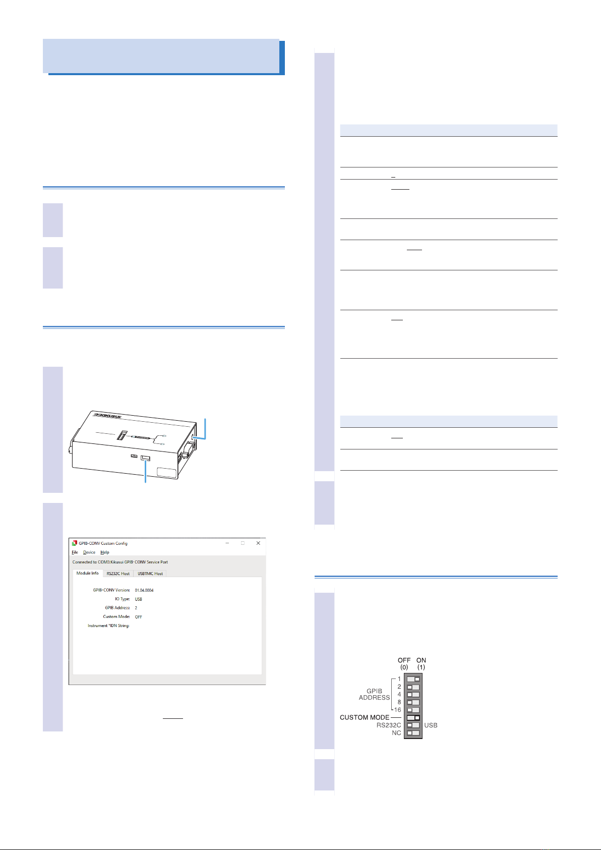
Set the PIA5100 DFU MODE switch to ON, and
connect the DC 5V power supply to the PIA5100.
5
Connect the PIA5100’s SERVICE PORT to the PC
using a USB cable.
6
In Windows Device Manager, check that STM
Device in DFU Mode is shown under Universal
Serial Bus controllers.
7
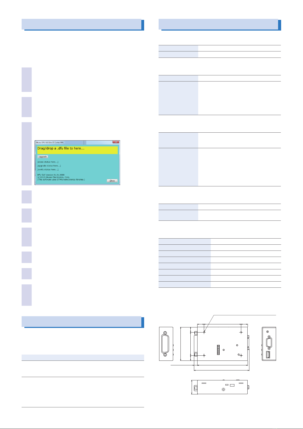
Drag the rmware that you downloaded (.dfu le)
to the Kikusui DFU GUI window.
8
Click Upgrade in the window.
Firmware updating starts.
9
When updating is complete, disconnect and
reconnect the PIA5100 DC 5V power supply to
restart the PIA5100.
This completes the rmware updating.
Troubleshooting
This section lists representative symptoms and remedies.
If following these remedies does not solve the problem, or if
none of the items listed here match your situation, contact your
Kikusui agent or distributor.
Symptom Remedy
The USB LED
does not light
green.
Check that the USB cable is connected properly.
Connect to a measuring instrument/power supply
that supports USBTMC.
The RS232C LED
does not light
green.
Check that the RS232C cable is connected
properly.
For the RS232C cable, use a crossover cable.
Check whether the measuring instrument’s/power
supply’s communication conditions are correct.
See “Installation and Preparation” (p. 3).
Specications
■GPIB port
GPIB specications IEEE488.1-1987
Primary address 0 to 30
■USB port
USB specications Standard type A socket, USB1.1 Full-Speed
Control target
measuring instrument/
power supply
Measuring instrument/power supply with
SCPI or IEEE488.2 language specications
complying with USBTMC-USB488. However,
operation is guaranteed only for measuring
instruments/power supplies listed in “Measuring
Instruments/power supplies Whose Operations
Have Been Checked” (p. 6).
■RS232C port
UART specications Dsub 9 pin
(Crossover cable connection with the measur-
ing instrument/power supply)
Control target
measuring instrument/
power supply
Measuring instrument/power supply with SCPI
or IEEE488.2 language specications and
whose communication conditions can be set to
19200, no parity, 8, 1, and no ow. However,
operation is guaranteed only for measuring
instruments/power supplies listed in “Measuring
Instruments/power supplies Whose Operations
Have Been Checked” (p. 6).
■SERVICE PORT connector
USB specications Mini B type socket, USB1.1 Full-Speed
Supported protocol Communication Device Class, Abstract Control
Model (CDC-ACM)
■General specications
Input power supply 5 V 0.25 A
DC IN 5V connector EIAJ#2
Operating temperature range 0 °C to 50 °C (32 °F to 122 °F)
Operating humidity range 20%rh to 85%rh (no condensation)
Storage temperature range -20 °C to 70 °C (-4 °F to 158 °F)
Storage humidity range 90%rh or less (no condensation)
Weight Approx. 200 g (7.05 oz).
Accessories See (p. 1).
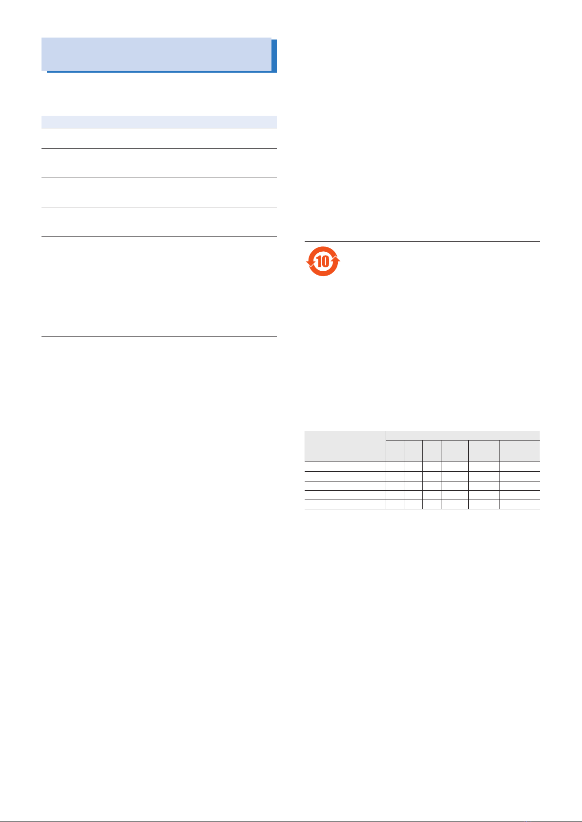
■Outline drawing
14
(0.55)
14
(0.55)
80 (3.15)
108 (4.25)
MAX125 (4.92)
Rear panel, four M3 screw holes
(max. insertion depth 8 mm (0.32))
MAX10 (0.39)
72 (2.83)
50
(1.97)
11
(0.43)
11
(0.43)
30 (1.18)
Unit: mm (inches)

6 PIA5100
Measuring Instruments/power supplies
Whose Operations Have Been Checked
This section lists measuring instruments/power supplies whose
operations have been checked and the recommended settings
(as of December 2017).
Model name Recommended settings
PLZ5W Series
Electronic Load
GPIB-CONV settings: RS232, CUSTOM MODE OFF
PWX Series
Regulated DC
Power Supply
GPIB-CONV settings: RS232, CUSTOM MODE OFF
Queries need to be inserted periodically to avoid
buer overrun.1
PMX Series
Regulated DC
Power Supply
GPIB-CONV settings: RS232, CUSTOM MODE OFF
Queries need to be inserted periodically to avoid
buer overrun.1
PWR-01 Series
Regulated DC
Power Supply
GPIB-CONV settings: RS232, CUSTOM MODE OFF
Queries need to be inserted periodically to avoid
buer overrun.1
PCZ1000A
AC Electronic
Load
GPIB-CONV settings: RS232, CUSTOM MODE ON
CUSTOM MODE settings:
Bitrate = 9 600
Stopbits = 2
Flow Control = Software
Termination Character = 0x0A
488.2 Block Transfer = No
IDN Query = IDN?
KISTD Mode = No
Queries need to be inserted periodically to avoid
buer overrun.1
1. For the setting procedure, see the manual for the measuring instrument to be
connected.
■Trademarks
Windows are either registered trademarks or trademarks
of Microsoft Corporation in the United States and/or other
countries.
Other company names and product names used in this manual
are generally trademarks or registered trademarks of the
respective companies.
■Copyright
Reproduction and reprinting of this operation manual, whole or
partially, without our permission is prohibited.
Both unit specications and manual contents are subject to
change without notice.
© 2016 Kikusui Electronics Corporation
环境保护使用期限
Environment-friendly Use Period
该标记为适用于在中华人民共和国销售的电子信息产品的环境保
护使用期限。
只要遵守有关该产品的安全及使用注意事项,从制造年月起计
算,在该年度内,就不会对环境污染、人身、财产产生重大的影
响。
产品的废弃请遵守有关规定。
产品的制造年月可以在以下网址中确认。
http://www.kikusui.co.jp/pi/
有毒有害物质或元素名称及含有標示
Name of hazardous materials and symbol of element in the
equipment and quantity
部件名称
有毒有害物质或元素
铅
Pb
汞
Hg
镉
Cd
六价铬
Cr(VI)
多溴联苯
PBB
多溴二苯醚
PBDE
印刷电路板组装品 × ○ ○ ○ ○ ○
内部接线 ○ ○ ○ ○ ○ ○
外壳 ○ ○ ○ ○ ○ ○
底盘组装品 ○ ○ ○ ○ ○ ○
辅助设备 ○ ○ ○ ○ ○ ○
本表格依据SJ/T 11364的规定编制。
○: 该部件所有均质材料的有毒有害物质的含量不超过GB/T 26572标准
所规定的极限值要求。
×: 该部件至少有一种均质材料的有毒有害物质的含量超过GB/T 26572
标准所规定的极限值要求。
Table of contents
Popular Media Converter manuals by other brands

Moxa Technologies
Moxa Technologies TCF-142-M-ST Quick installation guide

StarTech.com
StarTech.com IDE2SAT25 instruction manual

Linear Technology
Linear Technology LTC3118EUFD Demo Manual

Abicor Binzel
Abicor Binzel MF1 operating instructions

Bose
Bose FreeSpace 3 Application note

Euphonix
Euphonix FC726 installation manual

ICT
ICT ICT2412-10A instruction manual

Baumer
Baumer HUBNER BERLIN SAFETY POG 90 + ESL 90 Mounting and operating instructions

weha
weha LS-001 Operating instructions and parts manual

Avenview
Avenview SC-HDM2-HD42K-A user manual

Art
Art CleanBoxPRO Installation and operation

Linear Technology
Linear Technology LT8494 Demo Manual