Kikusui KFM2151 User manual

OPERATION MANUAL
FC Scanner
Part No. Z1-003-382, IB010911
May 2006
KFM2151

Use of Operation Manual
Please read through and understand this Operation Manual before operating the product. After reading,
always keep the manual nearby so that you may refer to it as needed. When moving the product to another
location, be sure to bring the manual as well.
If you find any misplaced or missing pages in this manual, they will be replaced. If the manual gets lost or
soiled, a new copy can be provided for a fee. In either case, please contact Kikusui distributor/agent, and
provide the “Kikusui Part No.” given on the cover.
This manual has been prepared with the utmost care; however, if you have any questions, or note any errors
or omissions, please contact Kikusui distributor/agent.
Reproduction and reprinting of this operation manual, in whole or in part, without written permission is
prohibited.
Both unit specifications and manual contents are subject to change without notice.
Copyright© 2006 Kikusui Electronics Corporation

KFM2151 i
Power Reqiorements of this Product
Power reqirements of this product have been changed and relevant sections of the Operation
Manual should be revised accordingly.
(Revision should be applied to items indicatedby a check mark .)
Input voltage
The input voltage of this product is VAC ,
and the voltage range is to VAC. Use the product within this range only.
Input voltage
The rating of this product’s input fuse is to VAC, and .
• To avoid electrical shock, always disconnect the power cord or
turn off the switchboard before attempting to check or replace the
fuse.
• Use a fuse element having a shape, rating, and characteristics
suitable for this product. The use of a fuse with a different rating
or one that short circuits the fuse holder may result in fire,
electric shock, or irreparable damage.
Power cord
The product is provided with power cords described below. If the cord has no power plug,
attach a power plug or crimp-style terminals to the cord in accordance with the wire colors
specified in the drawing.
• The attachment of a power plug or crimp-style terminals must be
carried out by qualified personnel.
WARNING
WARNING
Blue (NEUTRAL )
Brown (LIVE)
Green/Yellow (GND)
White (NEUTRAL)
Black (LIVE)
Green or Green/Yellow (GND)
Kikusui agents can provide you with suitable power cord.
For further information, contact Kikusui distributor/agent.
Without a power plugWithout a power plug
Plugs for Europe
Plugs for USA
Provided by Kikusui distributor/agent

ii KFM2151

KFM2151 iii
Safety Symbols
For the safe use and safe maintenance of this product, the following symbols are
used throughout this manual and on the product. Note the meaning of each of the
symbols to ensure safe use of the product. (Not all symbols may be used.)
or
Indicates that a high voltage (over 1000 V) is used here.
Touching the part causes a possibly fatal electric shock. If physical
contact is required by your work, start work only after youmake sure
that no voltage is output here.
DANGER Indicates an imminently hazardous situation which, if ignored, will result
in death or serious injury.
WARNING
Indicates a potentially hazardous situation which, if ignored, could result
in death or serious injury.
CAUTION
Indicates a potentially hazardous situation which, if ignored, may result
in damage to the product and other property.
Shows that the act indicated is prohibited.
Indicates a general danger, warning, or caution.
When this symbol is marked on the product, see the relevant sections in
this manual.
Protective conductor terminal.
Chassis (frame) terminal.
On (supply)
Off (supply)
In position of a bi-stable push control
Out position of a bi-stable push control
!

ivKFM2151
Safety Precautions
The following safety precautions must be observed to avoid fire hazards, electric
shock, accidents, and other failures. Keep them in mind and make sure to observe
them.
Using the product in a manner that is not specified in this manualmayimpairthe
protection functions provided by the product.
Users • This product must be used only by qualified personnel who
understand the contents of this operation manual.
•Ifunqualified personnel is to use the product, be sure the product is
handled under the supervision of qualified personnel (those who have
electrical knowledge). This is to prevent the possibility of personal
injury.
• Do not use the tester if youhave a heart problem such as heart
disease, if youare or may be pregnant, or if youwear a medical device
such as pacemaker.
Purpose of
use
•Never use the product for purposes other than the product's intended
use.
• This product is not designed or manufactured for general home or
consumer use.
Input power • Use the product within the rated input power voltage range.
• For applying power, use the power cord provided. For details, see the
respective page in the operation manual.
• This product is designed as an equipment of IEC Overvoltage
Category II (energy-consuming equipment supplied from the fixed
installation).
Cover • Some parts inside the product may cause physical hazards. Do not
remove the external cover.
Grounding • This product is an IEC Safety Class I equipment (equipment with a
protective conductor terminal). To prevent the possibility of electric
shock, be sure to connect the protective conductor terminal of the
product to electrical ground (safety ground).
!
Operation
Manual
Line
Voltage
GNL

KFM2151 v
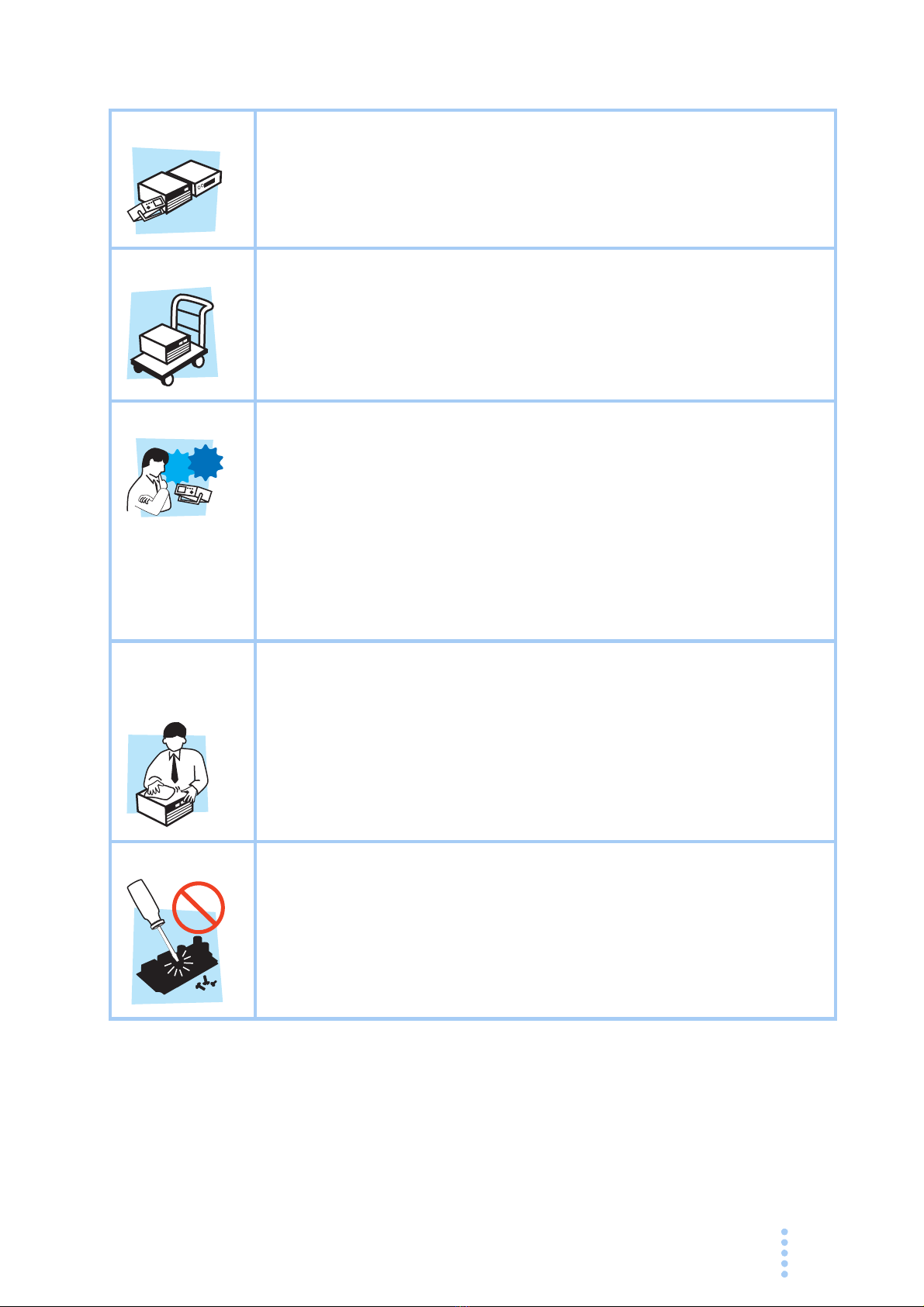
Installation • This product is designed for safe indoor use. Be sure to use it indoors.
•When installing this product, be sure to observe the description in
section 2.2, “Precautions Concerning Installation Location” in this
manual.
Relocation •Turn off the POWER switch, and disconnect all cables before
relocating the product.
•When relocating the product, be sure to include the manual.
Operation • Before using the product, be sure to check the input power voltage and
that there is no abnormality in the appearance of the power cord. Be
sure to remove the power plug from the outlet before checking it.
•Ifamalfunction or abnormality is detected on the product, stop using it
immediately, and remove the power plug from the outlet. Make sure
the product is not used until it is completely repaired.
• Use cables or wires with sufficiently large current capacity for output
wires and load cables.
• Do not disassemble or modify the product. If youneed to modify the
product, contact your Kikusui distributor/agent.
Maintenance
and
inspection
• To prevent the possibility of electric shock, make sure to unplug the
power plug before carrying out maintenance or inspection.
• Do not remove the external cover during maintenance or inspection.
• To maintain the performance and safe operation of the product, it is
recommended that periodic maintenance, inspection, cleaning, and
calibration be performed.
Service •Kikusui service engineers will perform internal service on the product.
If the product needs adjustment or repairs, contact your Kikusui
distributor/agent.
Check?

viKFM2151
How to Read This Manual
Preface
Thank you for purchasing the KFM2151 FC Scanner.
This manual is intended for first-time users of the KFM2151. It gives an overview of
the impedance measurement system and describes various settings, measurement
procedure, SCPI commands, maintenance, safety precautions, etc.
Read this manual thoroughly to use the functions of the KFM2151 effectively. You
can also review this manual when you are confused about an operation or when a
problem occurs.
For details on the individual instruments making up the impedance measurement
system such as the PLZ-4W Series and KFM2150 FC Impedance Meter, see the
respective operation manuals.
How to read this manual
This manual is designed to be read from beginning to end. We recommend that you
read the manual thoroughly from the beginning before using the KFM2151 for the
first time.
Related manuals
Only the basic aspects of the KFM2150 are described as part of the impedance
measurement system. For details, see the operation manual of the KFM2150.
Intended readers of this manual
This manual is intended for operators that control the impedance measurement
system and use the KFM2151 FC Scanner or persons teaching other users on how to
operate the KFM2151.
It assumes that the reader has knowledge about fuel cells and electrical aspects of
impedance measurement.
Information on SCPI commands is provided with the premise that the reader has
sufficient knowledge about controlling instruments using a personal computer.

KFM2151 vii
Structure
Below is the structure of the manual. A summary of each chapter is provided.
Chapter 1 General Description
This chapter gives a general description and introduces the features of the
KFM2151.
Chapter 2 Installation and Preparation
This chapter describes the procedures from unpacking to installation.
Chapter 3 Operation
This chapter mainly describes various setup procedures.
Chapter 4 Remote Control
This chapter describes the procedure for connecting the interface and the procedure
for transmitting commands to the KFM2151 using SCPI commands.
Chapter 5 Maintenance
This chapter covers maintenance of the KFM2151 including cleaning, inspecting,
calibrating, and troubleshooting.
Chapter 6 Specifications
This chapter contains the electrical and mechanical specifications of the KFM2151.

viii KFM2151
Notations used in the manual
•The KFM2151 FC Scanner is also simply referred to as KFM2151 in this
manual.
•The KFM2150 FC Impedance Meter is also simply referred to as KFM2150 in
this manual.
•The word computer used in the text is a collective term for personal computers
and workstations.
•The following markings are used in the explanations in the text.
Indicates a potentially hazardous situation which, if ignored, could result in
death or serious injury.
Indicates a potentially hazardous situation which, if ignored, may result in
damage to the product and other property.
Indicates information that you should know.
Explanation of terminology or operation principle.
Indicates reference to detailed information.
>
Indicates menu settings that you select. Menu items to the left of the greater-
than sign is are higher level menus.
SHIFT+key name (marked in blue)
Indicates an operation in which a switch marked in blue is pressed while
holding down the SHIFT key.
WARNING
CAUTION
DESCRIPTION
See

KFM2151 ix
Contents
Power Reqiorements of this Product - - - - - - - - - - - - - - - - - - - - - - - - - - - - - - - - - - - i
Safety Symbols - - - - - - - - - - - - - - - - - - - - - - - - - - - - - - - - - - - - - - - - - - - - - - - - -iii
Safety Precautions - - - - - - - - - - - - - - - - - - - - - - - - - - - - - - - - - - - - - - - - - - - - - - -iv
Howto Read This Manual - - - - - - - - - - - - - - - - - - - - - - - - - - - - - - - - - - - - - - - - - vi
Contents - - - - - - - - - - - - - - - - - - - - - - - - - - - - - - - - - - - - - - - - - - - - - - - - - - - - - ix
Contents by Function - - - - - - - - - - - - - - - - - - - - - - - - - - - - - - - - - - - - - - - - - - - - xiii
Front panel - - - - - - - - - - - - - - - - - - - - - - - - - - - - - - - - - - - - - - - - - - - - - - - - - - -xiv
Rear panel - - - - - - - - - - - - - - - - - - - - - - - - - - - - - - - - - - - - - - - - - - - - - - - - - - - -xvi
Chapter 1 General Description
1.1 About This Manual- - - - - - - - - - - - - - - - - - - - - - - - - - - - - - - - - - - - - - - - - 1-2
1.2 Overview- - - - - - - - - - - - - - - - - - - - - - - - - - - - - - - - - - - - - - - - - - - - - - - - 1-2
Impedance measurement system (scanner system) - - - - - - - - - - - - - - - 1-3
1.3 Features - - - - - - - - - - - - - - - - - - - - - - - - - - - - - - - - - - - - - - - - - - - - - - - - 1-3
1.4 Rack mounting option - - - - - - - - - - - - - - - - - - - - - - - - - - - - - - - - - - - - - - 1-4
Chapter 2 Installation and Preparation
2.1 Checking the Package Contents - - - - - - - - - - - - - - - - - - - - - - - - - - - - - - - 2-2
Accessories - - - - - - - - - - - - - - - - - - - - - - - - - - - - - - - - - - - - - - - - - - - 2-2
2.2 Precautions Concerning Installation Location - - - - - - - - - - - - - - - - - - - - - - 2-3
2.3 Precautions to Be Taken When Moving the Product - - - - - - - - - - - - - - - - - 2-4
2.4 Connecting the KFM2151 to the FC Impedance Meter - - - - - - - - - - - - - - - 2-5
2.5 Connecting the SENSING terminal and the fuel cell - - - - - - - - - - - - - - - - - 2-9
2.6 Connecting the Power Cord - - - - - - - - - - - - - - - - - - - - - - - - - - - - - - - - - 2-11
2.7 Precautions Concerning Grounding (Earth) - - - - - - - - - - - - - - - - - - - - - - 2-12
Chapter 3 Operation
3.1 Powering Up - - - - - - - - - - - - - - - - - - - - - - - - - - - - - - - - - - - - - - - - - - - - - 3-2
Turning on the POWER switch - - - - - - - - - - - - - - - - - - - - - - - - - - - - - 3-2
Checking the firmware version - - - - - - - - - - - - - - - - - - - - - - - - - - - - - - 3-2
3.2 Monitor - - - - - - - - - - - - - - - - - - - - - - - - - - - - - - - - - - - - - - - - - - - - - - - - - 3-2
3.3 Switching the monitor display (impedance/voltage) - - - - - - - - - - - - - - - - - - 3-3
3.4 Setting the Channels - - - - - - - - - - - - - - - - - - - - - - - - - - - - - - - - - - - - - - - 3-4
3.5 Logical Channel Configuration - - - - - - - - - - - - - - - - - - - - - - - - - - - - - - - - 3-9
3.6 Checking the Channels - - - - - - - - - - - - - - - - - - - - - - - - - - - - - - - - - - - - 3-11
3.7 CONFIG Settings- - - - - - - - - - - - - - - - - - - - - - - - - - - - - - - - - - - - - - - - - 3-12
3.8Channel Expansion - - - - - - - - - - - - - - - - - - - - - - - - - - - - - - - - - - - - - - - 3-13
Setting the master unit or slave unit (unit number) - - - - - - - - - - - - - - - 3-13
3.9 Performing the Scanning Operation- - - - - - - - - - - - - - - - - - - - - - - - - - - - 3-14
3.9.1 Impedance Scanning - - - - - - - - - - - - - - - - - - - - - - - - - - - - - - - - 3-14
Manual scanning - - - - - - - - - - - - - - - - - - - - - - - - - - - - - - - - - - - - - - 3-14
Auto scanning - - - - - - - - - - - - - - - - - - - - - - - - - - - - - - - - - - - - - - - - 3-14

xKFM2151
Contents
3.9.2 Voltage scanning- - - - - - - - - - - - - - - - - - - - - - - - - - - - - - - - - - - - 3-15
3.10 Alarms- - - - - - - - - - - - - - - - - - - - - - - - - - - - - - - - - - - - - - - - - - - - - - - - - 3-16
Alarm display - - - - - - - - - - - - - - - - - - - - - - - - - - - - - - - - - - - - - - - - - 3-16
Clearing alarms - - - - - - - - - - - - - - - - - - - - - - - - - - - - - - - - - - - - - - - - 3-17
3.11 Initializing to Factory Default Settings - - - - - - - - - - - - - - - - - - - - - - - - - - - 3-18
3.12 Switching from Remote to Local Mode - - - - - - - - - - - - - - - - - - - - - - - - - - 3-18
3.13 Channel and SENSING Terminal Assignment Table - - - - - - - - - - - - - - - - 3-19
Chapter 4 Remote Control
4.1 Overview- - - - - - - - - - - - - - - - - - - - - - - - - - - - - - - - - - - - - - - - - - - - - - - - 4-2
4.2 Instrument Interface Standards - - - - - - - - - - - - - - - - - - - - - - - - - - - - - - - - 4-2
4.3 Interface Setup- - - - - - - - - - - - - - - - - - - - - - - - - - - - - - - - - - - - - - - - - - - - 4-2
4.4 Overviewof Messages - - - - - - - - - - - - - - - - - - - - - - - - - - - - - - - - - - - - - - 4-5
4.4.1 Command Syntax - - - - - - - - - - - - - - - - - - - - - - - - - - - - - - - - - - - - 4-6
4.4.2 Parameters- - - - - - - - - - - - - - - - - - - - - - - - - - - - - - - - - - - - - - - - - 4-8
4.4.3 Default Conditions- - - - - - - - - - - - - - - - - - - - - - - - - - - - - - - - - - - 4-10
4.5 SCPI Commands - - - - - - - - - - - - - - - - - - - - - - - - - - - - - - - - - - - - - - - - - 4-11
4.5.1 IEEE 488.2 Common Commands - - - - - - - - - - - - - - - - - - - - - - - - 4-11
4.5.2 Channel Commands - - - - - - - - - - - - - - - - - - - - - - - - - - - - - - - - - 4-15
4.5.3 Releasing the Protection Function- - - - - - - - - - - - - - - - - - - - - - - - 4-19
4.5.4 Configuration Function- - - - - - - - - - - - - - - - - - - - - - - - - - - - - - - - 4-20
4.5.5 Trigger Function - - - - - - - - - - - - - - - - - - - - - - - - - - - - - - - - - - - - 4-22
4.5.6 Measurement Function - - - - - - - - - - - - - - - - - - - - - - - - - - - - - - - 4-23
4.5.7 Other Commands - - - - - - - - - - - - - - - - - - - - - - - - - - - - - - - - - - - 4-25
4.6 Status Registers and Status Report Function - - - - - - - - - - - - - - - - - - - - - 4-26
4.6.1 IEEE488.2 Register Model - - - - - - - - - - - - - - - - - - - - - - - - - - - - - 4-28
Status byte register - - - - - - - - - - - - - - - - - - - - - - - - - - - - - - - - - - - - - 4-28
IEEE 488.2 status event command - - - - - - - - - - - - - - - - - - - - - - - - - - 4-29
Standard event status register - - - - - - - - - - - - - - - - - - - - - - - - - - - - - 4-29
4.6.2 SCPI Register Model - - - - - - - - - - - - - - - - - - - - - - - - - - - - - - - - - 4-30
OPERation status register - - - - - - - - - - - - - - - - - - - - - - - - - - - - - - - - 4-30
QUEStionable status register - - - - - - - - - - - - - - - - - - - - - - - - - - - - - - 4-33
Preset Status- - - - - - - - - - - - - - - - - - - - - - - - - - - - - - - - - - - - - - - - - - 4-36
4.7 A List of Error Messages - - - - - - - - - - - - - - - - - - - - - - - - - - - - - - - - - - - - 4-37
4.8A List of Messages - - - - - - - - - - - - - - - - - - - - - - - - - - - - - - - - - - - - - - - - 4-40
4.9 Tutorial - - - - - - - - - - - - - - - - - - - - - - - - - - - - - - - - - - - - - - - - - - - - - - - - 4-43
4.9.1 Simple measurement procedure (MEASure) - - - - - - - - - - - - - - - - 4-43
4.9.2 Measurement procedure with a little more flexibility (CONFigure and
READ)4-44
4.9.3 Measurement procedure with flexibility (INITiate and FETCh) - - - - 4-45
Chapter 5 Maintenance
5.1 Cleaning and Inspection - - - - - - - - - - - - - - - - - - - - - - - - - - - - - - - - - - - - - 5-2
Cleaning the panels - - - - - - - - - - - - - - - - - - - - - - - - - - - - - - - - - - - - - 5-2
Inspecting the power cord - - - - - - - - - - - - - - - - - - - - - - - - - - - - - - - - - 5-2

KFM2151 xi
5.2 Calibration- - - - - - - - - - - - - - - - - - - - - - - - - - - - - - - - - - - - - - - - - - - - - - - 5-2
5.3 Malfunctions and Causes - - - - - - - - - - - - - - - - - - - - - - - - - - - - - - - - - - - - 5-3
Chapter 6 Specifications
6.1 Specifications - - - - - - - - - - - - - - - - - - - - - - - - - - - - - - - - - - - - - - - - - - - - 6-2
6.1.1 Scanning Function - - - - - - - - - - - - - - - - - - - - - - - - - - - - - - - - - - - 6-2
6.1.2 Communication Function- - - - - - - - - - - - - - - - - - - - - - - - - - - - - - - 6-3
6.1.3 General Specifications- - - - - - - - - - - - - - - - - - - - - - - - - - - - - - - - - 6-3
6.2 Outline Drawing- - - - - - - - - - - - - - - - - - - - - - - - - - - - - - - - - - - - - - - - - - - 6-4
Index

xii KFM2151
Contents

KFM2151 xiii
Contents by Function
Panel control
Basic operations
Situation Heading
Page
Switch between impedance scanning and voltage scanning
Switching the monitor
display (impedance/
voltage).
3-3
Impedance scanning Setting Setting the Channels. 3-4
Scanning Impedance Scanning. 3-14
Voltage scanning Setting Setting the Channels. 3-4
Scanning Voltage scanning. 3-15
Situation Heading
Page
Want to change the SENSING terminal Logical Channel
Configuration. 3-9
Forgot the SENSING terminal number
Want to scan manually Manual scanning. 3-14
Want to detect voltage drop and overvoltage
Voltage protection (only for
voltage scanning),
Alarms.
3-5
3-16
See
See

xivKFM2151
Front panel
IMPIMP
VOLTVOLT
VV
CHCH
OVPOVP
UVPUVP
RANGERANGE
TERMTERM
VOLT TERMCHANNEL
IMP VOLT SET
TERM
REMOTE
LOCAL
CONFIG
CH1 CH2
CH17 CH18
CH3
CH19
CH4
CH20
CH5
CH21
CH6
CH22
CH7
CH23
CH8
CH24
CH9
CH25
CH10
CH26
CH11
CH27
CH12
CH28
CH13
CH29
CH14
CH30
CH15
CH31
CH16
CH32
SCAN
FC SCANNER
MON
SHIFT
ALL SCAN
ALL CLR
ALM CLR
KFM2151
18
19
IMPIMP
VOLTVOLT VV
CHCH
OVPOVP
UVPUVP
RANGERANGE
TERMTERM
VOLT TERMCHANNEL
IMP VOLT SET
TERM
REMOTE
LOCAL
CONFIG
SCAN
MON
SHIFT
ALL SCAN
ALL CLR
ALM CLR
17 16 15 14 13 11
10987654321
12

KFM2151 xv
No. Name Description
Page
+SHIFT
1VOLT LED Illuminates when scanning voltage. 3-3
2IMP LED Illuminates when scanning impedance.
3CHANNEL Displays the selected channel. –
4UVP LED When setting the UVP for voltage scanning: Illuminates in green.
When an alarm is occurring: Illuminates in red. 3-5
3-16
5OVP LED When setting the OVP for voltage scanning: Illuminates in green.
When an alarm is occurring: Illuminates in red.
6TERM LED Illuminates when setting the SENSING terminal. 3-9
7RANGE LED Illuminates when setting the voltage scanning range. 3-5
8VOLT/TERM Displays the voltage, SENSING terminal number, etc. –
9Up/Down key.
Resolution: 1 –
Up/Down key that changes settings by a great amount.
Resolution: 10 times the and keys unless specified
otherwise.
–
10 SCANScanning start/stop key. The LED to the left of the key illuminates
while scanning. 3-14
ALL SCANScanning start/stop key for all channels when the channels are
expanded. The LED to the left of the key illuminates while scanning. 3-15
11 LOCAL Local mode switch key. 3-18
12 REMOTE LED Illuminates in remote control mode.
13 SHIFT Shift key. –
14 MONMonitor status switch key. 3-2
15 SET Set key. 3-4
TERM SENSING terminal setting key. 3-9
16 ALM CLR Clears the alarm on the selected channel. 3-17
ALL CLR Clears the alarm on all channels. 3-17
17 INP/VOLT Impedance scanning/voltage scanning switch key. 3-3
CONFIG Configuration setting key. 3-12
18Monitor LED. Channel (CH1 to CH32) monitor LED.
Not scanned: Not illuminated.
Pause: Illuminates in green.
Scanning: Illuminates in orange.
When an OVP or UVP alarm is occurring: Illuminates in red.
3-11
3-16
19 Feet Four locations on the bottom. –
See

xviKFM2151
Rear panel
No. Name Description
Page
1SENSINGSENSING terminal. 32 channels total.
Isolated from the chassis electric potential (withstand voltage of
250 V).
Rated input voltage: ±150 V(±200 Vpeak maximum).
Input impedance: Approx. 1 MΩ.3-9
2TERM- Lowpotential terminal of the SENSING terminal.
3TERM+ High potential terminal of the SENSING terminal.
4IN/OUT Scanning I/O signal terminal for impedance measurement. 2-5
5SCANNER IN/OUT Channel expansion terminal. 2-7
6POWER POWER switch. Press the ( ) side to turn the power on and the ( )
to turn the power off. 3-2
7AC INPUT AC inlet connector for the power cord.
8Serial number The serial number of the KFM2151. –
9RS232C RS232C cable connector for remote control. –
10 OPTIONTerminal for connecting to the KFM2150. 2-5
14
23
567
8910
See

General Description
This chapter gives a general description and introduces the
features of the KFM2151.

1-2 KFM2151
General Description
1.1 About This Manual
This manual describes the KFM2151 FC Scanner.
Impedance of fuel cells is measured using a system that combines the KFM2151,
KFM2150 FC Impedance Meter, and the PLZ-4W Series Electronic Load Unit.
For a description of the KFM2150 FC Impedance Meter and the PLZ-4W Series
Electronic Load Unit, see the operation manuals of the respective products.
Firmware version of the product to which this manual applies
This manual applies to KFM2151s with firmware version 1.0X.
Page 3-2 When making an inquiry about the product, please provide us with the following
information.
•Model (written on the front cover of this manual)
•Firmware version
•Serial number (indicated at the lower section on the rear panel)
1.2 Overview
The KFM2151 is a channel selector for the 32-channel voltmeter and impedance
meter. It is used as a component instrument of the impedance measurement system
as shown in Fig.1-1. By combining with the KFM2150 FC Impedance Meter, the
voltage and impedance of each stack of the fuel cell can be measured.
If it is not used in combination with the KFM2150 FC Impedance Meter, it can be
used as a multi-channel voltmeter.
The role of the scanner in the impedance measurement system is described in the
next section.
See
Table of contents